Viessmann Vitogate 300 Installation Instructions Manual
Hide thumbs
Also See for Vitogate 300:
- Installation and service instructions manual (28 pages) ,
- Supplementary documentation (27 pages) ,
- Installation and service instructions for contractors (21 pages)

Related Manuals for Viessmann Vitogate 300


Summary of Contents for Viessmann Vitogate 300
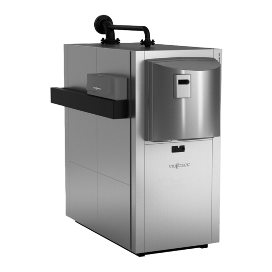
- Page 1 VIESMANN Installation instructions for contractors Vitocrossal 300 Type CT3B, 187 to 635 kW Gas condensing boiler VITOCROSSAL 300 Dispose after installation. 5614 451 GB 1/2014...
- Page 2 Safety instructions Please follow these safety instructions closely to prevent accidents and mate- rial losses. Safety instructions explained ■ The Code of Practice of relevant trade associations Danger ■ all current safety regulations as This symbol warns against the defined by DIN, EN, DVGW, TRGI, risk of injury.
-
Page 3: Table Of Contents
Index Intended use....................... Preparing for installation Clearance dimensions..................Installation sequence Siting and levelling the boiler................Converting the boiler door opening..............Assembly when supplied in sections..............11 Connections on the heating water side..............13 Connections on the flue gas side................. 14 ■... -
Page 4: Intended Use
Intended use The appliance is only intended to be installed and operated in sealed unven- ted heating systems that comply with EN 12828, with due attention paid to the associated installation, service and operating instructions as well as the details in the datasheet. It is only designed for the heating up of heating water. -
Page 5: Clearance Dimensions
Clearance dimensions Note The hinge pins can be repositioned so that the boiler door opens to the left. Dimensions in brackets are minimum clearances. 500 (400) 500 (50) (400) Boiler Burner Adjustable anti-vibration feet D/E Anti-vibration boiler supports... - Page 6 Clearance dimensions (cont.) Rated heating output kW 1000 1100 1500 1500 1500 Observe the installed burner length Adjustable anti-vibration boiler feet C Permissible load 1200 Number Anti-vibration boiler supports Permissible load 1200 E 1500 D 1750 D c (front) / number mm/pce 125/2 375/2...
-
Page 7: Siting And Levelling The Boiler
Siting and levelling the boiler Note Lifting eyes are welded to the top of the boiler for attaching the lifting gear. Alter- natively, use the specified holes in the boiler floor. Lifting gear attachment points: A Lifting the complete appliance C Lifting the heat exchanger module B Lifting the combustion chamber module... - Page 8 Siting and levelling the boiler (cont.) Note When refitting the base support, tighten Base support D may be removed by the four screws with 70 Nm torque. undoing four screws to make handling easier. 1. Insert adjusting screws F (inside the 2.
-
Page 9: Converting The Boiler Door Opening
Siting and levelling the boiler (cont.) Note Anti-vibration boiler supports Remove transport protectors. Any unevenness in the floor should be max. 1 mm, to ensure the spring ele- 3. Level the boiler using the adjusting ments are evenly loaded. screws. Position the boiler supports underneath the boiler. - Page 10 Converting the boiler door opening (cont.) Note When converting the boiler door hinges by moving hinge pins A to the r.h. side, ensure that gasket frame B is pressed centrally onto boiler door gasket D when the boiler door is closed (see detail);...
-
Page 11: Assembly When Supplied In Sections
Assembly when supplied in sections... - Page 12 Assembly when supplied in sections (cont.) Please note 7. Remove all protruding sealant inside Scratches on parts that come into the combustion chamber. Check contact with flue gas can lead to whether sufficient sealant has been corrosion. applied all around to prevent any Never put tools or other objects gaps appearing in the combustion into the combustion chamber.
-
Page 13: Connections On The Heating Water Side
Connections on the heating water side A Boiler return 1 E Safety connection (safety valve) for 187 and 248 kW: PN 6 DN 65 for 187 to 314 kW: R 1¼ for 314 kW: PN 6 DN 80 for 408 to 635 kW: R 1½ for 408 to 635 kW: PN 6 DN 100 F Boiler water temperature sensor B Drain: R 1... -
Page 14: Connections On The Flue Gas Side
Connections on the heating water side (cont.) Danger 2. Note There is a risk of injury when Never connect heat consumers to the working on pressurised compo- safety connector. nents. Only open the connections on the Make all necessary connections. heating water side after the boiler Connecting a single heating circuit: has been depressurised. - Page 15 Connections on the flue gas side (cont.) 1. Insert the boiler flue connection 3. Fill the siphon with water and fit it to (Vitoset accessories) into the flue the boiler. outlet as far as it will go. Note Connect the flue outlet to the flue pipe via the shortest possible run, with a slight incline (min.
-
Page 16: Fitting The Thermal Insulation
Fitting the thermal insulation Boiler shell thermal insulation A Black side outwards Note on steps 2 to 4 Note Connect the thermal insulation mat with Before fitting the thermal insulation, an overlap. check that the serial number on the type plate matches the serial number stam- ped on the boiler front panel. -
Page 17: Thermal Insulation Mat, Front
Fitting the thermal insulation (cont.) Thermal insulation mat, front... -
Page 18: Thermal Insulation Mats, Back
Fitting the thermal insulation (cont.) Thermal insulation mats, back A Thermal insulation mat, back B Combustion chamber thermal insu- lation mat Note The actual thermal insulation mats deliv- ered may differ from those shown here. -
Page 19: Front Fixing Rails, Retaining Bracket And Cross Braces
Fitting the thermal insulation (cont.) Front fixing rails, retaining bracket and cross braces M8x16 M8x16 M8x16 M6x10... - Page 20 Fitting the thermal insulation (cont.) 3. Position both cross braces B onto 1. Insert two M 8x16 screws each into the top of front fixing rails A, then front fixing rails A and onto retaining hook the rails onto the boiler floor at brackets C from the inside and the holes provided and secure with secure with M 8x16 screws.
-
Page 21: Rear And Central Fixing Rails
Fitting the thermal insulation (cont.) Rear and central fixing rails M8x16 M8x16 M6x10 M6x10 1. Secure both central rails D to the 2. Secure both rear fixing rails E to the cross braces at the top using retaining brackets. M 8x16 screws and to the base sup- port at the bottom using M 6x10 screws. - Page 22 Fitting the thermal insulation (cont.) ° ° 1. Hook into place two side panels. 3. Then tighten all rail screws. Note Note Check clearance and squareness Rear fixing rails may be secured towards the fixing rails. below on the base support using Side panels should be parallel to M 6x10 screws.
-
Page 23: Corner Rails
Fitting the thermal insulation (cont.) Corner rails A Clip (2 pce per rail; supplied with the fixings) Information on step 1 Information on step 2 Corner rails can be fitted on the r.h. or Hook the corner rails onto the fixing rails the l.h. -
Page 24: Side Panels And Burner Cables
Fitting the thermal insulation (cont.) Side panels and burner cables lÖ A Burner cables fA and lÖ Please note Note Burner cables can be damaged Hook side panels into the slots provided, by high temperatures. starting at the bottom and working Prevent contact with hot compo- upwards. -
Page 25: Front Panels
Fitting the thermal insulation (cont.) Front panels Note on steps 1 and 2 Using strain relief B, secure burner cables A to the lower front panel and the control unit. Hook front panels into the fixing rail slots. -
Page 26: Boiler Door
Fitting the thermal insulation (cont.) Boiler door A Boiler door for third party burners. B Boiler door for Unit version Delivered condition: 408 to 635 kW with MatriX radiant burner For 187 to 314 kW subject to order: A or B Note Danger Tighten the screws on the boiler door... - Page 27 Fitting the thermal insulation (cont.) Boiler door version for third party burners Operation with third party burners (187 to 635 kW) with ventilation option...
- Page 28 Danger Leaks can result in a risk of poisoning through escaping gas. Seal in plug carefully. Boiler door for Unit version Viessmann MatriX radiant burners (187 to 314 kW) have no inspection port.
-
Page 29: Back Panels, Covers, Cap And Boiler Water Temperature Sensor
Fitting the thermal insulation (cont.) Back panels, covers, cap and boiler water temperature sensor 4.8x19 A Quarter turn closure E Boiler water temperature sensor § B Damping washer C Cap (supplied with the control unit) D Cover panel Note Please note Insert the sensor and boiler water tem- Damaged capillaries will result in perature sensor into the sensor well as... -
Page 30: Top Panels And Reinforcement Struts
Fitting the thermal insulation (cont.) Top panels and reinforcement struts Information on step 1 Information on step 2 Secure reinforcement struts onto cross Fit top panel D, then position the rein- braces C with screws. forcement strut B behind top panel D Position reinforcement struts A at the and secure to cross brace C. -
Page 31: Preparing The Control Unit Installation
Fitting the thermal insulation (cont.) Preparing the control unit installation Note Boiler coding card (included in the prod- uct pack) Boiler water temperature sensor § is included with the control unit. - Page 32 Fitting the thermal insulation (cont.) Boiler control unit installation and Note service instructions After connecting the cables and leads, secure mounting bracket fascia A to the mounting bracket.
-
Page 33: Type Plate
Fitting the thermal insulation (cont.) Type plate A Type plate B Boiler coding card Note on Affix the type plate to an accessible side panel. -
Page 34: Connecting The Neutralising System
Connecting the neutralising system Neutralising system installation 4. Connect drain hose D to the con- and operating instructions densate drain of the neutralising sys- tem and run to drainage system E. 1. Site neutralising system A either behind or adjacent to the boiler. 2. -
Page 35: Making The Safety Connections
Making the safety connections Note Please note ■ Install all pipe connections free of load Unsuitable water quality can and torque stress. damage the boiler shell. ■ Equip boilers with a safety valve that is Only fill the boiler with water that type-tested to TRD 721 [or local regu- complies with the "Water quality lations] and is marked according to the... -
Page 36: Fuels
Mounting the burner (cont.) c: The circle of burner fixing holes Danger Leaks can result in a risk of poi- and the blast tube aperture match the dimensions recommended by the soning through escaping gas. KRW/VSO. Prior to commissioning, check the boiler door gasket for correct ■... -
Page 37: Commissioning And Adjustment
Adjusting the burner (cont.) Note Rated Pressure drop on Fully open the rotary damper in the flue heating output the hot gas side outlet when adjusting the burner. mbar Service instructions Adjust the highest gas throughput of the burner to the rated boiler heating output. You can adjust the burner so that the content lies between 9 and 10.5 %;... - Page 40 Viessmann Werke GmbH&Co KG Viessmann Limited D-35107 Allendorf Hortonwood 30, Telford Telephone: +49 6452 70-0 Shropshire, TF1 7YP, GB Fax: +49 6452 70-2780 Telephone: +44 1952 675000 www.viessmann.com Fax: +44 1952 675040 E-mail: info-uk@viessmann.com...