Table of Contents
Advertisement
Quick Links
NABCO ENTRANCES Inc.
S82 W18717 Gemini Drive, P.O. Box 906
Muskego, WI 53150
Phone: 877-622-2694
Fax:
888-679-3319
Technical Assistance: 866-622-8325
www.nabcoentrances.com
Email: info@nabcoentrances.com
Magnum IV Control
Wiring & Adjustment Manual
for
Gyro Tech Swing Door Operators
Part Number 15-10682
1-4-06 Revision
Advertisement
Table of Contents

Related Manuals for Nabco GYRO TECH Magnum IV Control

Summary of Contents for Nabco GYRO TECH Magnum IV Control
- Page 1 NABCO ENTRANCES Inc. S82 W18717 Gemini Drive, P.O. Box 906 Muskego, WI 53150 Phone: 877-622-2694 Fax: 888-679-3319 Technical Assistance: 866-622-8325 www.nabcoentrances.com Email: info@nabcoentrances.com Magnum IV Control Wiring & Adjustment Manual Gyro Tech Swing Door Operators Part Number 15-10682 1-4-06 Revision...
- Page 2 Replacement labels and literature may be obtained from local NABCO ENTRANCES INC. authorized distributors. If the name of the local distributor is unknown, contact NABCO ENTRANCES INC. at (877-622- 2694) for assistance. Do not place finger or uninsulated tools inside the electrical control box. Touching wires or other parts inside the enclosure may cause electrical shock, serious injury or death.
-
Page 3: Table Of Contents
Magnum IV Control Manual for Gyro Tech Swing Door Systems Table of Contents Page 4 To The Installer Overview Page 4 Specifications Page 5 Visual Indicators Page 5 Magnum IV Diagnostic LED Function Chart Page 6 Wiring Connectors Page 7-8 Door Positions Page 8 Adjustments... -
Page 4: To The Installer
The owner should follow these instructions to determine whether the door is operating properly and should immediately call for service if there is any malfunction. All installation changes and adjustments must be made by qualified, NABCO trained technicians. Earlier versions of Gyro Tech GT300, GT400, GT500 and GT710 Swing Door Overview Operators can be retrofitted with the newer Magnum IV Control Board. -
Page 5: Specifications
These two indicators, the Magnum LEDs and the Diagnostic Daughter Board LEDs, are designed to work in tandem to enable the technician to easily adjust the Magnum IV control or troubleshoot a problem installation. NABCO ENTRANCES strongly recommends the use of the optional Diagnostic Daughter Board to assist the technician when installing or servicing the Magnum IV control. -
Page 6: Magnum Iv Diagnostic Led Function Chart
Magnum IV Control Manual for Gyro Tech Swing Door Systems Magnum IV Diagnostic LED Function Chart LED Color Door Status LED Status Explanation Closed Green Magnum is not activated, door is in Latch Check area Opening Fast Flash Magnum is opening door, not yet in Back Check area Back Check &... -
Page 7: Wiring Connectors
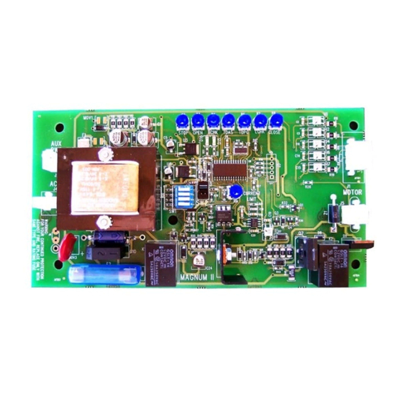
Magnum IV Control Manual for Gyro Tech Swing Door Systems Wiring Connectors: There are four connectors located on the control board labeled J2, J3, J4, and J5 (Figure 2). There is a re- settable fuse 1 (F1) and a replaceable fuse 2 (F2). J1 is the signal input. -
Page 8: Door Positions
Magnum IV Control Manual for Gyro Tech Swing Door Systems J4 is the 120 VAC input connector. J5 is the motor feed. It is a four-pin connector that connects to the motor braking module (not used with GT-710) mounted at the end of the Magnum control board. This module uses a resistor & diode to slow the door down if J5 is accidentally unplugged while the door is in the open position. -
Page 9: Adjustments
The amount of energy stored in the door and imparted to an object on impact is determined by both the weight and speed of the door. NABCO ENTRANCES INC. recommends setting opening and closing speeds as slow as owners will accept, AND below the maximums stated by ANSI. - Page 10 Magnum IV Control Manual for Gyro Tech Swing Door Systems Stop Adjustment (STOP): When an object is sensed in the path of a moving door by a swing side safety mat or ACUGARD sensor connected to the control board through terminal # 3 (Violet wire) and the door is not in back check, this feature determines whether the door stops, slowly opens, or slowly closes.
-
Page 11: Dip Switches
Magnum IV Control Manual for Gyro Tech Swing Door Systems Latch Check Adjustment (LCHK): This sets latch check speed. Latch check takes place from about the last 10º of sweep to the full-close position. The recommended starting position is 11 o’clock. Clockwise rotation increases latch check speed. -
Page 12: Troubleshooting
Magnum IV Control Manual for Gyro Tech Swing Door Systems Troubleshooting: Symptom Action/Cause Solution Operator does not function 1. Check Fuse 2 (F2). 1. Replace fuse 2. Check for 120 VAC at 2. Check incoming power. If power is good, check connector J5 connection to motor. - Page 13 Magnum IV Control Manual for Gyro Tech Swing Door Systems Troubleshooting continued …. Presence Sensor does not 1. All units: No power to 1. Check harness wiring as per applicable section function sensor or defective sensor. 2. All units: Sensor not 2.
-
Page 14: Section A - Wiring And Adjustment For Gt-300, Gt-400 And Gt-500 Operators
Magnum IV Control Manual for Gyro Tech Swing Door Systems Section A Wiring and Adjustment for GT-300, GT-400 and GT-500 Operators This section details the installation and adjustments of the Magnum IV control in a GT-300, GT-400 and GT-500 swing door unit. -
Page 15: Required Wiring Harnesses
Magnum IV Control Manual for Gyro Tech Swing Door Systems Required Wiring Harnesses: The following harnesses are necessary to complete the installation (see below): Power Harness, Magnum Board Part # 21-9933 (for single door) 14-5883 for Simultaneous Pair door) Main Harness Assy, Magnum Board Part # 22-10065 (for single door) 22-10270 (for Simultaneous Pair door) -
Page 16: Wiring For Rocker Switch
Magnum IV Control Manual for Gyro Tech Swing Door Systems Wiring for Rocker switch: Rocker Switch (part # 10-3528) is available. Connect the red wire to activation input, the white wire to 24VAC common and the black wire to activation signal of sensing device. Wiring for Break –... -
Page 17: General Wiring - Single Diagram
Magnum IV Control Manual for Gyro Tech Swing Door Systems Page 17 www.NabcoEntrances.com 1/4/06... -
Page 18: General Wiring - Simultaneous Pair
Magnum IV Control Manual for Gyro Tech Swing Door Systems Page 18 www.NabcoEntrances.com 1/4/06... -
Page 19: Section B - Retrofit Kit Manual, Model 300/400/500 Swing Door System With Magnum Iv Control
Magnum IV Control Manual for Gyro Tech Swing Door Systems Section B Retrofit Kit Manual Model 300/400/500 Swing Door System With Magnum IV Control This section offers instructions on how to upgrade an existing GT300/400/500 installation with the Magnum IV and related hardware. -
Page 20: Hard Ware Kit List
Magnum IV Control Manual for Gyro Tech Swing Door Systems Hard Ware Kit List: This kit has been shipped with the following installation hardware. -01 11-10293-01 Magnum Board Retrofit Kit for Single Swinger -02 11-10293-02 Magnum Board Retrofit Kit for Simultaneous Pair Swinger Part # Part Description Notes... -
Page 21: Conversion Of A Gt300/400/500 To A Magnum Iv
Magnum IV Control Manual for Gyro Tech Swing Door Systems Conversion of a GT300/400/500 to a Magnum IV : Shut off power to the header. Uninstall the swing operator from the header. Remove all wires and the switch harness from the operator. Remove the control board and the appropriate wiring from the header. - Page 22 Magnum IV Control Manual for Gyro Tech Swing Door Systems Cut the connectors from the Brown and Black wires on the GT 300/400/500 Magnum Micro Switch Harness P/N 21-9934 as shown below. Connect the Brown and Black wires to Continuous Safety” input of Terminal Block. ( Between Terminal Block #3 violet and 16 - M IGURE ICRO...
- Page 23 Magnum IV Control Manual for Gyro Tech Swing Door Systems Plug the power harness into the Magnum IV board. Connect the green wire (ground) to the header chassis, black 120 VAC wire to black through thermal protector, and white wire to white wire as shown on the next page.
-
Page 24: General Wiring - Single Diagram
Magnum IV Control Manual for Gyro Tech Swing Door Systems Page 24 www.NabcoEntrances.com 1/4/06... -
Page 25: General Wiring - Simultaneous Pair
Magnum IV Control Manual for Gyro Tech Swing Door Systems Page 25 www.NabcoEntrances.com 1/4/06... -
Page 26: Section C - Wiring And Adjustment For Gt-710 Operators
Magnum IV Control Manual for Gyro Tech Swing Door Systems Section C Wiring and Adjustment for GT-710 Operators This section details the installation and adjustments of the Magnum IV control in a GT-710 swing door unit. Step 1: Install all components as per the applicable hardware installation manual. Step 2: Connect all wiring and harnesses as per the following wiring information as they pertains to wiring and adjustments for GT-710 Operator. -
Page 27: General Wiring Diagram - Single Door
Magnum IV Control Manual for Gyro Tech Swing Door Systems Page 27 www.NabcoEntrances.com 1/4/06... -
Page 28: Wiring Diagram For Wall Switch Activation
Magnum IV Control Manual for Gyro Tech Swing Door Systems Page 28 www.NabcoEntrances.com 1/4/06... -
Page 29: Wiring Diagram For Simultaneous Pairs
Magnum IV Control Manual for Gyro Tech Swing Door Systems Hold Open Page 29 www.NabcoEntrances.com 1/4/06... -
Page 30: Transformer Installation And Wiring For 240 Volts
Magnum IV Control Manual for Gyro Tech Swing Door Systems Page 30 www.NabcoEntrances.com 1/4/06... -
Page 31: Wiring Diagram For Radio Activation
Magnum IV Control Manual for Gyro Tech Swing Door Systems Page 31 www.NabcoEntrances.com 1/4/06... -
Page 32: Wiring Diagram For 4 Wire Radio Receiver And Electric Strike
Magnum IV Control Manual for Gyro Tech Swing Door Systems BLACK WHITE VIOLET ORANGE BROWN Page 32 www.NabcoEntrances.com 1/4/06... -
Page 33: Wiring Diagram For Electric Strike And Fire Alarm Systems
Magnum IV Control Manual for Gyro Tech Swing Door Systems Page 33 www.NabcoEntrances.com 1/4/06...