Table of Contents
Advertisement
TopPage
In the interest of user-safety the oven should be restored to its original condition and only parts identical to those
specified should be used.
WARNING TO SERVICE PERSONNEL: Microwave ovens contain circuitry capable of producing very high
voltage and current, contact with following parts may result in a severe, possibly fatal, electrical shock. (High
Voltage Capacitor, High Voltage Power Transformer, Magnetron, High Voltage Rectifier Assembly, High
Voltage Harness etc..)
PRECAUTIONS TO BE OBSERVED BEFORE AND
DURING SERVICING TO AVOID POSSIBLE EXPO-
SURE TO EXCESSIVE MICROWAVE ENERGY
CHAPTER 1. WARNING TO SERVICE PERSONNEL
CHAPTER 2. MICROWAVE MEASUREMENT PRO-
CEDURE
CHAPTER 3. FOREWORD AND WARNING
CHAPTER 4. PRODUCT DESCRIPTION
CHAPTER 5. OPERATION
CHAPTER 6. TROUBLESHOOTING GUIDE
SERVICE MANUAL
COMMERCIAL MICROWAVE OVEN
MODELS
CONTENTS
CHAPTER 7. TEST PROCEDURES
CHAPTER 8. TOUCH CONTROL PANEL ASSEMBLY
CHAPTER 9. PRECAUTIONS FOR USING LEAD-
FREE SOLDER
CHAPTER 10. COMPONENT REPLACEMENT AND
ADJUSTMENT PROCEDURE
CHAPTER 11. CIRCUIT DIAGRAMS
Parts List
RCD1200M
S3802RCD12MP/
R-CD1200M
This document has been published to be used for
after sales service only.
The contents are subject to change without notice.
Advertisement
Table of Contents

Related Manuals for Sharp R-CD1200M


Summary of Contents for Sharp R-CD1200M
- Page 1 RCD1200M SERVICE MANUAL S3802RCD12MP/ COMMERCIAL MICROWAVE OVEN R-CD1200M MODELS In the interest of user-safety the oven should be restored to its original condition and only parts identical to those specified should be used. WARNING TO SERVICE PERSONNEL: Microwave ovens contain circuitry capable of producing very high voltage and current, contact with following parts may result in a severe, possibly fatal, electrical shock.
-
Page 2: Table Of Contents
CONTENTS PRECAUTIONS TO BE OBSERVED BEFORE CHAPTER 8. TOUCH CONTROL PANEL ASSEM- AND DURING SERVICING TO AVOID POSSIBLE EXPOSURE TO EXCESSIVE MICROWAVE ENER- SPECIAL FUNCTION FOR SERVICING ..8-1 SERVICING FOR BRINTED WIRING BOARDS............. 8-4 CHAPTER 1. WARNING TO SERVICE PERSON- CHAPTER 9. -
Page 3: Precautions To Be Observed Before
Before servicing an operative unit, perform a microwave emission check as per the Microwave Measurement Procedure outlined in this service manual. If microwave emissions level is in excess of the specified limit, contact SHARP ELECTRONICS CORPORATION immediately @1-800-237-4277. If the unit operates with the door open, service person should 1) tell the user not to operate the oven and 2) contact SHARP ELECTRONICS CORPORATION and Food and Drug Administration's Center for Devices and Radiological Health immediately. -
Page 4: When The Testing Is Completed
RCD1200M CHAPTER 1. RCD1200M WARNING TO SERVICE PERSONNEL Service Manual Microwave ovens contain circuitry capable of producing very high voltage and current, contact with following parts may result in a severe, possibly fatal, electrical shock. (Example) High Voltage Capacitor, High Voltage Power Transformer, Magnetron, High Voltage Rectifier Assembly, High Voltage Harness etc.. Read the Service Manual carefully and follow all instructions. -
Page 5: Chapter 2. Microwave Measurement
RCD1200M CHAPTER 2. RCD1200M MICROWAVE MEASUREMENT PROCEDURE Service Manual A. Requirements: 1) Microwave leakage limit (Power density limit): The power density of microwave radiation emitted by a microwave oven should not exceed 1mW/ at any point 5cm or more from the external surface of the oven, measured prior to acquisition by a purchaser, and thereafter (through the use- ful life of the oven), 5 mW/cm at any point 5cm or more from the external surface of the oven. -
Page 6: Chapter 3. Foreword And Warning
Service Manual FOREWORD This Manual has been prepared to provide Sharp Electronics Corp. Service Personnel with Operation and Service Information for the SHARP MICROWAVE OVEN, R-CD1200M. It is recommended that service personnel carefully study the entire text of this manual so that they will be qualified to render satisfactory customer service. -
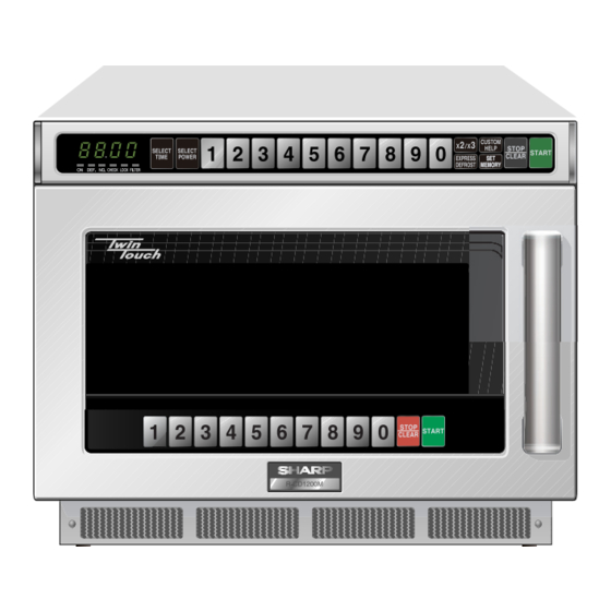
Page 7: Chapter 4. Product Description
RCD1200M CHAPTER 4. RCD1200M PRODUCT DESCRIPTION Service Manual [1] SPECIFICATIONS ITEM DESCRIPTION Power Requirements Single phase, 60Hz, A.C. only 1.9kW Power Consumption 120V-16A Power Output 1200W Operating frequency 2450 MHz 17-1/2” (W) x 20-1/2” (D) x 13-5/8” (H) Outside Dimensions 445mm (W) x 520mm (D) x 346mm (H) (including feet) 14”... -
Page 8: Oven Diagram
RCD1200M [3] OVEN DIAGRAM 1. OVEN 1. Touch control panels 2. Door latch openings 3. Ceramic shelf 4. Splash cover 5. Oven light 6. Air intake filter 4 18 3 7. Air intake openings 8. Door seals and sealing surfaces 9. -
Page 9: Chapter 5. Operation Description Of Operating Se- Quence
RCD1200M CHAPTER 5. RCD1200M OPERATION Service Manual [1] DESCRIPTION OF OPERATING SEQUENCE The following is a description of component functions during oven operation. 1. OFF CONDITION 2. The shut-off relay (RY-4) contacts close completing circuits to turn on the oven lamp and antenna motors. (For details, refer to Figure O-1) 3. -
Page 10: Oven Schematic
RCD1200M [2] OVEN SCHEMATIC 1. Off Condition SCHEMATIC NOTE: CONDITION OF OVEN 1. DOOR CLOSED 2. “ . “ APPEARS ON DISPLAY Figure O-1. Oven Schematic-Off Condition 2. Cooking Condition SCHEMATIC NOTE: CONDITION OF OVEN 1. DOOR CLOSED. 2. SELECT TIME PAD TUCHED.. 3. -
Page 11: Description And Function Of Components
RCD1200M [3] DESCRIPTION AND FUNCTION OF COMPONENTS 1. DOOR OPEN MECHANISM 3. If the door is opened, and the contacts of the primary interlock relay and secondary interlock switch of the same circuit fail to open, the 1. The handle lever is pulled. monitor fuse blows simultaneously with closing of the monitor 2. - Page 12 RCD1200M During cooking, they operate. After cooking, they will operate at least 4. The large electric currents flow through the high voltage winding of for 1 minute and the maximum operating time is 4 minutes. When the the high voltage transformer. temperature of the magnetron thermistor becomes bellow 110°C, the 5.
-
Page 13: Chapter 6. Troubleshooting Guide
RCD1200M CHAPTER 6. RCD1200M TROUBLESHOOTING GUIDE Service Manual Never touch any part in the circuit with your hand or an uninsulated tool while the power supply is connected. When troubleshooting the microwave oven, it is helpful to follow the Sequence of Operation in performing the checks. Many of the possible causes of trouble will require that a specific test be performed. - Page 14 RCD1200M 6 – 2...
- Page 15 RCD1200M SPECIFICATION OF ERROR Outline Operation when error occurs Display in operation usually When a basic performance and the function are ruined Displaying and heating stop EE0, EE1, EE2, EE3, EE8 When the dangers of the state of the high temperature and the ignition, etc. are Displaying and heating stop foreseen When you mistake the setting of the heating time...
-
Page 16: Chapter 7. Test Procedures
RCD1200M CHAPTER 7. RCD1200M TEST PROCEDURES Service Manual [1] A: MAGNETRON ASSEMBLY TEST 1. Disconnect the power supply cord, and then remove outer case and rear cover. 2. Open the door and block it open. 3. Discharge high voltage capacitor. 4. -
Page 17: D: High Voltage Capacitor (1) And/Or (2) Test
RCD1200M 5. Reconnect all leads removed from components during testing. 6. Reinstall the rear cover and the outer case (cabinet). 7. Reconnect the power supply cord after the rear cover and the outer case are installed. ASYMMETRIC RECTIFIER 8. Run the oven and check all functions. HIGH VOLTAGE RECTIFIER 2. -
Page 18: G: Monitor Switch (1) And/Or (2) Test
RCD1200M 7. Reconnect the power supply cord after the rear cover and the outer case are installed. 8. Run the oven and check all functions. NOTE: If the door sensing switch contacts fail in the open position and the door is closed, the blower motor, stirrer motors and oven light will be acti- vated by RY1. -
Page 19: I: Fuse 12A (1) (2) Test
RCD1200M [9] I: FUSE 12A (1) (2) TEST 1. Disconnect the power supply cord, and then remove outer case and rear cabinet. 2. Open the door and block it open. 3. Discharge high voltage capacitor. 4. If the fuse is blown, check the magnetron, high voltage capacitor, high voltage rectifier assembly, according to the “TEST PROCEDURE” before replacing the blown fuse. -
Page 20: M: Noise Filter Test
RCD1200M [13] M: NOISE FILTER TEST 1. Disconnect the power supply cord, and then remove outer case and rear cabinet. Source Source (White) (Black) NOISE FILTER 2. Open the door and block it open. DISCHARGE RESISTOR 3. Discharge high voltage capacitor. 470K 1/2W FUSE 4. -
Page 21: O: Control Unit Test
RCD1200M 7) Reconnect the power supply cord after the rear cover and the outer case are installed. 8) Run the oven and check all functions. [15] O: CONTROL UNIT TEST The following symptoms indicate a defective control unit. Before replacing the control unit, perform the Key units test (Procedure) to determine if con- trol unit is faulty. -
Page 22: R: Antenna Sensor Test
RCD1200M 1) If it is open, the relay unit is defective. 6. Check the open and /or short of the transformer primary coil on the relay unit. 1) If it is open and /or short, it is defective. 7. Check the state of the relays contacts RY-1, RY-2 and RY-3 using an ohmmeter. 1) The relay contacts should be open. -
Page 23: Special Function For Servicing
RCD1200M CHAPTER 8. RCD1200M TOUCH CONTROL PANEL ASSEMBLY Service Manual [1] SPECIAL FUNCTION FOR SERVICING This oven has the special functions for servicing as shown in the table 1 ~ 4. By using the special function, service person can check the using time or the using number of times for the electrical parts. Also service person can check the AC supply voltage and /or set the standard voltage. - Page 24 RCD1200M For example: Procedure to check the total cooking number of times (example, 957700 times) and using time (example, 1260 hours) of MG 1 and set 0 hours after MG1 is replaced. : no sound : 0.1 second sound : 2.0 second sound : (0.06 sec.
- Page 25 Operation Display Indicator Sound plug in (within 20 sec.) SELECT POWER SET MEMORY (within 20 sec.) START STOP/CLEAR CUSTOM HELP (model name) cd12 (date) XXXX (time) XXXX STOP/CLEAR #1: The display will show “cd12” means model R-CD1200M. 8 – 3...
-
Page 26: Servicing For Brinted Wiring Boards
RCD1200M [2] SERVICING FOR BRINTED WIRING BOARDS 1. Precautions for Handling Electronic Components b) On some models, the power supply cord between the printed wiring boards and the oven proper is long enough that they This unit uses CMOS LSI in the integral part of the circuits. When han- may be separated from each other. -
Page 27: Chapter 9. Precautions For Using Lead
RCD1200M CHAPTER 9. RCD1200M PRECAUTIONS FOR USING LEAD-FREE SOLDER Service Manual Employing lead-free solder The “Main PWB” of this model employs lead-free solder. This is indicated by the “LF” symbol printed on the PWB and in the service manual. The suffix letter indicates the alloy type of the solder. -
Page 28: Chapter 10. Component Replacement And Adjustment Procedure Warnings
4. If the outer case (cabinet) is not fitted. WARNING FOR WIRING To prevent an electric shock, take the following precau- Oven cavity. tions. 3) Sharp edge: 1. Before wiring, Bottom plate, Oven cavity, Waveguide flange Chassis 1) Disconnect the power supply cord. support and other metallic plate. -
Page 29: Power Transformers (1) And/Or (2) Removal
RCD1200M 10.Remove the eight (8) screws holding the rear cover and exhaust 12.Now, the rear cover with the fan motor and exhaust cover is free. cover to the bottom plate, power supply cord angle, intake duct and NOTE: Do not forget to re-connect the wire leads to the exhaust fan exhaust duct. -
Page 30: Power Supply Cord Replacement
RCD1200M 3. Discharge two high voltage capacitors. CAUTION: 1) DISCHARGE THE TWO HIGH VOLTAGE CAPACITOR BEFORE TOUCHING ANY OVEN COMPONENTS OR 4. Remove the two (2) screws holding the capacitor unit angle to the WIRING. intake duct assembly or the exhaust duct assembly. 2) DO NOT REPLACE ONLY THE HIGH VOLTAGE REC- 5. -
Page 31: Exhaust Fan Removal
RCD1200M [9] EXHAUST FAN REMOVAL 1. Disconnect the power supply cord and then remove the outer case 4. Make sure that the connector of the exhaust fan has been discon- and the rear cover, referring to “OUTER CASE AND REAR COVER nected from the wire harness. -
Page 32: Door Sensing Switch/Secondary Interlock Switches (1), (2) And Monitor Switches (1), (2) Replacement
RCD1200M NOTE: 1) Before attaching a new key unit, remove remaining adhe- sive on the panel fixing plate surfaces completely with a Cushion soft cloth soaked in alcohol. 2) When attaching the key unit to the panel fixing plate, adjust the lower edge and left edge of the key unit to the Vinyl tape (W 20mm x L 520mm) correct position of panel fixing plate. -
Page 33: Door Replacement
RCD1200M 2. After adjustment, check the following. Switch lever A 1. In and out play of door remains less than 0.5mm when in the Latch lever latched position. Latch hook 2. The door sensing switch and secondary interlock switches (1), (2) interrupt the circuit before the door can be opened. -
Page 34: Door Disassembly
RCD1200M [18] DOOR DISASSEMBLY 1. CHOKE COVER REMOVAL 3) Stick the key unit firmly to the key fixing plate by rubbing with soft cloth to prevent scratching. 1. Remove the door assembly from oven cavity, referring to “DOOR REMOVAL”. 4. SWITCH UNIT REMOVAL 2. - Page 35 RCD1200M 8. DOOR CASE REMOVAL 9. NOTE FOR POSITION OF HARNESS AND PIPE After removing door panel; Before the door panel is reinstalled, make sure that the pipe should be positioned at the correct place. And the harness should pass through 1.
-
Page 36: Circuit
RCD1200M CHAPTER 11. RCD1200M CIRCUIT DIAGRAMS Service Manual [1] Figure S-1. Pictorial Diagram Magnetron temp.fuse (1) Gray Magnetron (1) Magnetron thermistor (1) Blue (Blue case) This main wire harness should be back to the original position as shown in Rear view, after High voltage the wire leads are connected to the magnetron capacitor (1) - Page 37 RCD1200M High voltage High voltage rectifier (1) capacitor (1) Magnetron (1) Asymmetric rectifier (1) Main wire harness Power transformer (1) White/White Blue High voltage capacitor (2) CPU harness High voltage rectifier (2) Oven lamp socket Asymmetric rectifier (2) Magnetron (2) LEFT SIDE VIEW Power transformer (2) Wiring of high voltage components...
- Page 38 RCD1200M Main wire harness 3 WHT NOTE: The red and blue wire leads to the cabinet side terminals of RY2 and RY3 should go through inside the core of CT1 Cook relay (1) Main wire Cook relay (2) harness (Blue case) Primary interlock relay RY1 (Blue case)
- Page 39 RCD1200M [2] Figure S-2. Switching Power Supply Unit Circuit 11 – 4...
- Page 40 RCD1200M [3] Figure S-3. Relay Unit Circuit NOTE: IF NOT SPECIFIED : 1/4W J% : 1SS133 RTRNPA162DR : NOT INSERT PARTS CN-D 1N4002x4 : CHECK POINT D292 D291 VRS1 S10K300 D294 D293 CN-A V-SENS D-12 GND-1 AC120V O.L. PCJ-124D3M CN-E 24V-2 24V 2 24V-1...
- Page 41 RCD1200M [4] Figure S-4. Control Unit/ Antenna sensor/ Microwave Sensor Circuit 11 – 6...
- Page 42 RCD1200M [5] Figure S-5. Printed Wiring Board CONTROL UNIT ANTENNA SENSOR SWITCH UNIT RELAY UNIT MICROWAVE SENSOR SWITCHING POWER SUPPLY UNIT 11 – 7...
-
Page 43: Parts List
PARTS LIST COMMERCIAL MICROWAVE OVEN HOW TO ORDER REPLACEMENT PARTS To have your order filled promptly and correctly, please furnish the following information. R-CD1200M MODEL 1. MODEL NUMBER 2. REF. NO. 3. PART NO. 4. DESCRIPTION Parts marked "*" may cause undue microwave exposure. - Page 44 RCD1200M [1] OVEN PARTS 7-15 4-64 7-21 6-15 4-48 7-21 4-63 4-34 4-12 7-15 7-21 7-25 2-2-1 6-13 7-13 4-11 4-48 4-63 7-21 1-18 7-21 4-60 7-21 4-10 7-26 7-21 2-10 7-21 Vinyl insulation tape: 20mm (W) x 520mm (L) 4-69 4-62 4-59...
- Page 45 RCD1200M PRICE PART PARTS CODE DESCRIPTION RANK MARK RANK [1] OVEN PARTS ELECTRIC PARTS Sensor assembly (Exhaust thermistor) FDTCTA239WRKZ Exhaust motor assembly FMOT-A031WRKZ Temperature fuse 120C (Oven) QFS-TA015WRE0 Magnetron thermistor assembly DH-HZA017WRKZ Power supply cord FACCDA122WREZ Noise filter FPWBFA383WRKZ UL fuse 12A QFS-BA011WRE0 Fuse holder QFSHDA009WRE0...
- Page 46 RCD1200M PRICE PART PARTS CODE DESCRIPTION RANK MARK RANK [1] OVEN PARTS 4-42 Hinge cover PCOVPA480WRFZ 4-43 Sensor cover PCOVPA496WRFZ 4-44 Lamp filter PFILWA064WRPZ 4-45 Lamp glass PGLSPA720WREZ 4-46 Cushion PCUSGA761WRPZ 4-47 PSKR-A462WRPZ Partition angle S 4-48 GLEGPA033WRE0 4-49 Partition cover GCOVPA022WRPZ 4-50 Cushion B...
- Page 47 RCD1200M [2] DOOR AND CONTROL PANEL PARTS 3-3-6 3-3-8 3-3-3 3-3-4 3-3-2 3-3-1 3-3-7 3-3-8 3-3-5 5-34 5-20 5-17 5-28 5-18 5-3-2 5-34 5-18 5-3-1 5-17 5-19 5-21 5-33 5-14 5-30 5-25 5-26 5-31 5-29 5-11 5-27 5-32 5-24 5-13 5-10 5-16 5-12...
- Page 48 RCD1200M PRICE PART PARTS CODE DESCRIPTION RANK MARK RANK [2] DOOR AND CONTROL PANEL PARTS CONTROL PANEL PARTS CPU protect sheet PSHEPB332WREZ Control unit DPWB-A573DRKZ 3-3-1 Key unit FUNTKB179WREZ 3-3-2 C/P case GCOVAA389WRPZ 3-3-3 Display window GMADIA189WRFZ 3-3-4 Panel grille GWAKPB142WRFZ 3-3-5 Panel cap R...
- Page 49 RCD1200M INDEX PRICE PART PRICE PART PARTS CODE PARTS CODE RANK MARK RANK RANK MARK RANK LRTNPA001DRZZ 2-5-30 [ D ] LRTNPA002DRZZ 2-5-31 DDAI-A214WRKZ 1-2-1 LSTPPA260WRFZ 2-5-11 DDUC-A071WRKZ 1-4-2 LSTPPA261WRFZ 2-5-5 DDUC-A072WRKZ 1-4-17 LSUB-A137WRPZ 1-4-38 DH-HZA017WRKZ 1-1-4 LX-BZA132WREZ 1-7-16 DPWB-A565DRKZ 1-1-24 LX-BZA138WREZ 1-7-17...
- Page 50 RCD1200M PRICE PART PARTS CODE RANK MARK RANK PSKR-A464WRPZ 1-4-55 [ Q ] QFS-BA011WRE0 1-1-8 QFSHDA009WRE0 1-1-9 QFS-TA014WRE0 1-1-15 QFS-TA015WRE0 1-1-3 QSOCLA026WRZZ 1-1-16 QSW-MA085WRE0 1-1-12 [ R ] RC-QZA322WRZZ 1-1-10 RLMPTA086WRZZ 1-1-17 RMOT-A016WRZZ 1-1-18 RMOT-A026WRZZ 1-1-19 RMOTDA209WRE0 1-1-20 RTRN-A768WRZZ 1-1-21 RV-MZA358WRZZ 1-1-14 [ T ]...
- Page 52 EndPage COPYRIGHT © 2008 BY SHARP CORPORATION ALL RIGHTS RESERVED. No part of this publication may be reproduced, stored in retrieval systems, or transmitted in anyform or by any means, electronic, mechanical, photocopying, re- cording, or other wise, without prior written permission...