Advertisement
HOLD
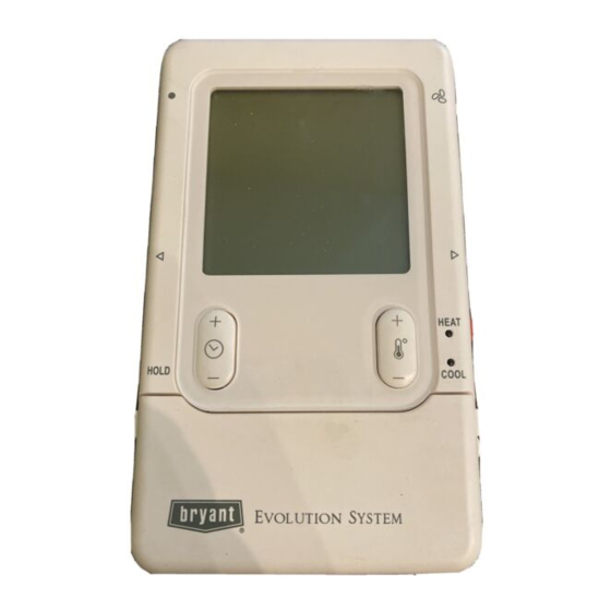
Evolution Control™
SYSTXBBUID01
NOTE: Read the entire instruction manual before starting the
installation.
This symbol → indicates a change since the last issue.
TABLE OF CONTENTS
SAFETY CONSIDERATIONS .....................................................1
INTRODUCTION ..........................................................................1
INSTALLATION AND START-UP OVERVIEW ......................1
INSTALLATION ...........................................................................1
INITIAL POWER-UP....................................................................5
QUICK START..............................................................................6
INSTALL / SERVICE MENUS....................................................7
OPERATIONAL INFORMATION.............................................11
TROUBLESHOOTING ...............................................................12
SAFETY CONSIDERATIONS
Read and follow manufacturer instructions carefully. Follow all
local electrical codes during installation. All wiring must conform
to local and national electrical codes. Improper wiring or installa-
tion may damage Evolution Control System. Recognize safety
information. This is the safety-alert symbol
symbol on the equipment and in the instruction manual, be alert to
the potential for personal injury. Understand the signal words
DANGER, WARNING, and CAUTION. These words are used
with the safety-alert symbol. DANGER identifies the most serious
hazards, which will result in severe personal injury or death.
Installation and Start-Up Instructions
Evolution™ Control
SYSTXBBUID01
HEAT
COOL
OFF
A03149
. When you see this
-1-
Cancels: NEW
WARNING signifies a hazard, which could result in personal
injury or death. CAUTION is used to identify unsafe practices,
which would result in minor personal injury or product and
property damage. NOTE is used to highlight suggestions which
will result in enhanced installation, reliability, or operation.
INTRODUCTION
The Evolution System consists of intelligent communicating
components (User Interface, variable speed furnace or fan coil, AC
or HP), which continually communicate with each other via a
four-wire connection called the ABCD bus. Conventional 24-volt
signals on dedicated wires are not needed. Commands, operating
conditions, and other data are passed continually between the
components over the ABCD bus. The result is a new level of
comfort, versatility, and simplicity.
An Evolution System consists of a Evolution Control™ (thermo-
stat plus much more) and a variable-speed furnace or FE fan coil.
They support controlled ventilation, humidification, dehumidifica-
tion, and air quality control. Either a two-speed (communicating),
or a standard 24 vac controlled outdoor unit may be used.
When using conventional outdoor units, the variable-speed furnace
or fan coil provides the 24 volt signals needed to control them.
Also, the Evolution Network Interface Module (NIM) allows
connection of a conventional HRV or ERV without the need for a
separate wall control.
All system components are controlled through the wall mounted
Evolution Control™, which replaces the conventional thermostat
and provides the homeowner with a single wall control for all the
features of the system.
INSTALLATION AND START-UP OVERVIEW
This instruction covers installation of the Evolution Control™
only. Physical installation instructions for the indoor, outdoor
equipment and accessories are provided with each unit.
Setup, commissioning, operation, and troubleshooting of the
Evolution System is covered only in this installation instruction. It
is your guide to connecting the system components and commis-
sioning the system once all the physical components are installed.
Special screen prompts and start-up capabilities are provided in the
Evolution System to simplify and lead you through the initial
commissioning of the system. So:
• Install the Evolution Control™ according to this instruction.
• Install the indoor unit, outdoor unit, and accessories according
to their instructions.
• Wire the complete system according to this instruction.
• Setup, commission, and operate the system according to this
instruction to assure yourself a smooth and trouble free
start-up.
INSTALLATION
A. Step 1 - Check Equipment and Job Site
INSPECT EQUIPMENT - File claim with shipping company,
prior to installation, if shipment is damaged or incomplete.
II UID01-0-1
02-04
Advertisement
Table of Contents

Related Manuals for Bryant Evolution Control SYSTXBBUID01


Summary of Contents for Bryant Evolution Control SYSTXBBUID01
-
Page 1: Table Of Contents
Installation and Start-Up Instructions Evolution™ Control SYSTXBBUID01 Cancels: NEW II UID01-0-1 02-04 WARNING signifies a hazard, which could result in personal injury or death. CAUTION is used to identify unsafe practices, which would result in minor personal injury or product and property damage. - Page 2 B. Step 2 — Evolution Control™ Location and Wiring RECESS MOUNT — This provides the thinnest mounting con- Considerations figuration (See Fig. 3). The backplate containing the recessed terminal block can be mounted directly to the wall by cutting a WARNING: ELECTRICAL SHOCK HAZARD hole 1 ½″...
- Page 3 Surface Mount Backplate to wall Interlocking Tabs (4) A03187 Fig. 4—Surface Mount Backplate A03191 Fig. 7—Surface Mount Assembly A04017 A03188 Fig. 5—Thin Decorative Backplate Fig. 8—Large Decorative Backplate Recessed terminal block in wall 1 ˝ wide by 2 ˝ high Recessed Mount Interlocking Tabs (4) A03190...
- Page 4 6. Secure mounting plastic to wall using two screws and anchors provided. Humidity/OAT Fan Button 7. Adjust length and routing of each wire to reach each wire Button entry on the connector backplate. Strip ¼ inch of insulation from each wire. Display Screen (LCD) 8.
-
Page 5: Initial Power-Up
The User Interface display will light up and indicate that it is now Variable-Speed ″ESTABLISHING COMMUNICATIONS WITH EQUIPMENT Furnace/Fan Coil User Interface PLEASE WAIT″. The User Interface will automatically continue by ″SEARCHING FOR INDOOR EQUIPMENT″, followed by Green ″SEARCHING FOR OUTDOOR EQUIPMENT″ (See Figure 15). Yellow Once the indoor and outdoor equipment has been found, the ABCD... -
Page 6: Quick Start
C. Section 3 — Selecting Electric Heater button (NO selection) will return to the Equipment Summary screen where you can back up to any of the equipment selection If the indoor unit is a fan coil and the electric heater is not screens and perform changes. -
Page 7: Install / Service Menus
C. Override Cooling Schedule INSTALL/SERVICE 1. Press the blue COOL button. Cooling mode is confirmed EQUIPMENT SUMMARY when the blue LED next to the COOL button is lit. INSTALL SETUP 2. Use the TEMP (+/−) button to select your desired cooling CHECKOUT SERVICE temperature. - Page 8 SETUP = THERMOSTAT: DEHUM AIRFLOW: AUTO MODE SETUP: • NORMAL (default) • Enable/Disable Auto Changeover mode (default=Enable). • HIGH • Auto Changeover Time may be adjusted 5 to 120 minutes, NORMAL airflow adjustment is used during dehumidifying. If (default = 30 minutes). duct sweating is an issue, selecting HIGH will increase the dehumidifying airflow speed and reduce the sweating.
- Page 9 SETUP = HEAT PUMP / AC: CLEAN INTERVAL: COOLING LOCKOUT: • 60 to 180 days of operation (default=90) • NONE (default) Interval at which the Clean Ventilator Pre-filter notification will turn on. • 45° F. SETUP = UV LIGHTS • 50° F. UV LIGHTS INSTALLED: •...
- Page 10 Checkout = HEAT PUMP HEATING LOCKOUT TIMER: • HIGH HEAT RUNTIME: 5 min. • Seconds • LOW HEAT RUNTIME: 5 min. If a lockout timer is active, this will show the current time value. See furnace manual for details on lockout timers. •...
-
Page 11: Operational Information
Run Times: Ten-Minute Staging Timer • Lifetime hours of operation in heating, cooling, and how long In multistage heating or cooling, this timer prevents any higher the unit has been powered. stage from turning on until the preceding stage has been on for 10 minutes. -
Page 12: Troubleshooting
FAN COIL disappear and the day/time will reappear. Code 44 - Motor Communication Fault Code 41 - Blower Motor Fault © 2004 Bryant Heating & Cooling Systems 7310 W. Morris St. Indianapolis, IN 46231 —12— Printed in U.S.A. iiuid01-0-1 Catalog No. 809-60019...