
Related Manuals for Siemens SIRIUS 3RN2


Summary of Contents for Siemens SIRIUS 3RN2
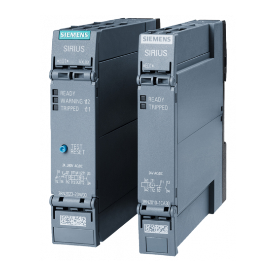
- Page 1 SIRIUS Monitoring and control devices 3RN2 Thermistor motor protection relay Manual Edition 10/2016 siemens.com...
- Page 3 ___________________ Introduction ___________________ Safety notes ___________________ ATEX SIRIUS ___________________ Description Monitoring and control devices SIRIUS 3RN2 thermistor motor ___________________ Mounting protection relay ___________________ Connection Manual ___________________ Functions Alarm, error and system ___________________ messages ___________________ Technical data ___________________ CAx data ___________________...
- Page 4 Note the following: WARNING Siemens products may only be used for the applications described in the catalog and in the relevant technical documentation. If products and components from other manufacturers are used, these must be recommended or approved by Siemens. Proper transport, storage, installation, assembly, commissioning, operation and maintenance are required to ensure that the products operate safely and without any problems.
-
Page 5: Table Of Contents
Mounting the devices on a standard mounting rail ..............29 Disassembling devices from a standard mounting rail ............30 Mounting the devices on a wall ....................31 Removing the devices from the wall ..................32 SIRIUS 3RN2 thermistor motor protection relay Manual, 10/2016, A5E34244868002A/RS-AA/001... - Page 6 Alarm, error and system messages ....................... 51 Function charts........................51 LED displays .......................... 54 Technical data ............................57 Technical data in Siemens Industry Online Support .............. 57 CAx data ............................... 59 Dimension drawings ..........................61 Circuit diagrams ............................ 65 Spare parts/accessories ........................67 Index ..............................
-
Page 7: Introduction
Online Support The Online Support in the Service&Support portal is an extensive information system for all questions relating to Siemens products and solutions. This service enables direct and central access to in-depth information concerning the products, systems and applications for industry and to a large number of programming, configuration, and application examples. - Page 8 Are you looking for product information such as technical data, updates or FAQs? The "Product Support" section of the Service&Support portal offers an extensive collection of all information about the Siemens Industry Automation and Drive Technologies products and solutions: ● Answers to frequently asked questions (FAQs) ●...
- Page 9 (manuals), which are located in the product support Under mySupport, you have the opportunity to create and manage you own compilations in a structure of their own. Link: My Documentation Manager (http://support.automation.siemens.com/WW/view/en/38715968) SIRIUS 3RN2 thermistor motor protection relay Manual, 10/2016, A5E34244868002A/RS-AA/001...
-
Page 10: Datamatrix Code
(http://support.automation.siemens.com), such as operating instructions, manuals, data sheets, FAQs, etc. We provide the SIEMENS Industry Support app free of charge for this purpose and it can be used on most commercially available smart phones and tablets. The SIEMENS Industry Support app is available for iOS and Android-based devices and can... -
Page 11: Standards/Regulations/Approvals
(https://support.industry.siemens.com/cs/ww/en/ps). Declaration of conformity The manufacturer declares that the thermistor motor protection relays of the SIRIUS 3RN2 series in the designs marketed by us comply with the applicable basic safety and health requirements of the EC Directives* stated (including amendments) and that the stated standards* were applied in their design and construction. -
Page 12: Article No. Scheme
8 Special versions Example 3 R N SIRIUS thermistor motor protection relay, 2nd generation, type A PTC, 1 sensor circuit, automatic reset, screw- type terminals, 1 CO, 24 V, 50/60 Hz AC/DC, monostable SIRIUS 3RN2 thermistor motor protection relay Manual, 10/2016, A5E34244868002A/RS-AA/001... -
Page 13: Safety Notes
Recycling and disposal Dispose of existing packing material in accordance with applicable regulations or recycle it. The SIRIUS 3RN2 thermistor motor protection relays can be recycled thanks to a low- pollutant manufacturing process. For environmentally-friendly recycling and disposal of your electronic waste, please contact a company certified for the disposal of electronic waste. -
Page 14: Intended Use
Intended Use of Hardware Products This equipment is only allowed to be used for the applications described in the catalog and in the technical description, and only in conjunction with non-Siemens equipment and components recommended by Siemens. Correct transport, storage, installation and assembly, as well as careful operation and maintenance, are required to ensure that the product operates safely and without faults. -
Page 15: Atex
3RN2 thermistor motor protection relays must be adapted to the applicable type of protection. The machine or plant must shut down immediately if the SIRIUS 3RN2 thermistor motor protection relay is tripped, even if connected through a frequency converter. This must be implemented with circuitry. - Page 16 ATEX 3.1 Safety and commissioning instructions for hazardous areas A SIRIUS 3RN2 thermistor motor protection relay set to "automatic RESET" mode will be reset automatically after the recovery time has elapsed, without the RESET button being pressed. An additional ON button has to be used to ensure that the motor does not start up automatically following tripping.
- Page 17 You can find the currently valid safety values in the Siemens Industry Online Support (https://support.industry.siemens.com/cs/ww/en/ps/). Installation and commissioning SIRIUS 3RN2 thermistor motor protection relays are suitable for snap-on mounting onto a 35 mm standard rail in accordance with EN 60715 or for screw mounting with an adapter (accessory).
- Page 18 User test (repeat test) Repeat testing in accordance with EN 60079-17 can be combined with the user test. Operation of the SIRIUS 3RN2 thermistor motor protection relay must be discontinued if test results are negative. The test must be performed by a qualified person familiar with the specified standards.
-
Page 19: Use In Areas Subject To An Explosion Hazard Due To Gases Or Dust
You will find further information on explosion protection (ATEX) on the Internet (http://www.siemens.com/sirius/atex). All ATEX-certified 3RN2 thermistor motor protection relays meet the requirements of Category 2 (EN ISO 13849-1): ● 3RN2011 ● 3RN2012-..30 ● 3RN20.3 SIRIUS 3RN2 thermistor motor protection relay Manual, 10/2016, A5E34244868002A/RS-AA/001... - Page 20 ATEX 3.2 Use in areas subject to an explosion hazard due to gases or dust SIRIUS 3RN2 thermistor motor protection relay Manual, 10/2016, A5E34244868002A/RS-AA/001...
-
Page 21: Description
Device overview Device description General information SIRIUS 3RN2 thermistor motor protection relays are thermal protection devices that are suitable, in combination with type A PTC thermistors, for monitoring temperatures of electrical drives, transformer windings, oils, bearings, air, etc. The most frequent application is monitoring of three-phase motors in which the motor manufacturer has fitted a PTC sensor into every winding overhang and in which these PTC sensors are connected in series. - Page 22 TNF (rated response temperature of the sensor): Tripping temperature Restart temperature 3 sensors TNF +3K TNF -7K 6 sensors TNF -4K TNF -19K (The specified temperatures are limit values.) SIRIUS 3RN2 thermistor motor protection relay Manual, 10/2016, A5E34244868002A/RS-AA/001...
- Page 23 You can see the rated response temperatures by the colors of the thermistor sensor cables because the colors are standardized: TNF (°C) Color code white/gray white/brown white/white green/green red/red brown/brown gray/gray blue/blue white/blue white/black black/black blue/black blue/red white/green white/red SIRIUS 3RN2 thermistor motor protection relay Manual, 10/2016, A5E34244868002A/RS-AA/001...
- Page 24 Never use bimetallic switches in applications subject to an explosion hazard! Because of their non-standardized tripping characteristic, bimetallic switches must not be used in applications where there is an explosion hazard. Use type A PTC sensors instead! SIRIUS 3RN2 thermistor motor protection relay Manual, 10/2016, A5E34244868002A/RS-AA/001...
-
Page 25: Device Versions
Description 4.3 Device versions Device versions SIRIUS 3RN2 thermistor motor protection relays are available in the following versions: ● 3RN2000 compact units ● 3RN2010 standard units ● 3RN2012-.BW31 bistable devices ● 3RN2011, 3RN2012-.B.30, 3RN2013 standard units with ATEX approval ● 3RN2023 devices with ATEX approval and 2 sensor circuits for warning and... -
Page 26: Area Of Application
Direct motor protection: ● At increased ambient temperatures ● When switching frequency is too high ● When starting and braking operations are too long ● Used together with frequency converters (low speeds) SIRIUS 3RN2 thermistor motor protection relay Manual, 10/2016, A5E34244868002A/RS-AA/001... -
Page 27: Mounting
The figures below show a 22.5-mm housing. The overall width, overall depth, terminals (type and number of terminals) and accessories and mounted components are similar may differ from the actual product. SIRIUS 3RN2 thermistor motor protection relay Manual, 10/2016, A5E34244868002A/RS-AA/001... -
Page 28: Terminal Coding
Mounting 5.2 Terminal coding Terminal coding You can fit the terminals with coding pins (3ZY1440-1AA00). This helps you to avoid errors when replacing the terminals. SIRIUS 3RN2 thermistor motor protection relay Manual, 10/2016, A5E34244868002A/RS-AA/001... -
Page 29: Mounting The Devices On A Standard Mounting Rail
Figure Place the back of the device onto the upper edge of the standard mounting rail. Press the lower half of the device against the DIN rail until the device engages. SIRIUS 3RN2 thermistor motor protection relay Manual, 10/2016, A5E34244868002A/RS-AA/001... -
Page 30: Disassembling Devices From A Standard Mounting Rail
Step Instructions Figure Press the device downwards. Pull the lower half of the device away from the standard mounting rail. Lift the device from the upper edge of the DIN rail. SIRIUS 3RN2 thermistor motor protection relay Manual, 10/2016, A5E34244868002A/RS-AA/001... -
Page 31: Mounting The Devices On A Wall
Insert the head screws through the corresponding elongated holes in the fixing lugs. Screw the device securely onto the level surface. Tightening torque: 1 Nm SIRIUS 3RN2 thermistor motor protection relay Manual, 10/2016, A5E34244868002A/RS-AA/001... -
Page 32: Removing The Devices From The Wall
● The terminals have been removed or disconnected. Procedure Step Instructions Figure Hold the device firmly. Unscrew the cap screws. Lift the device from the level surface. Remove the securing brackets from the device. SIRIUS 3RN2 thermistor motor protection relay Manual, 10/2016, A5E34244868002A/RS-AA/001... -
Page 33: Connection
The position of the label corresponds to the position of the respective terminal. NOTICE Risk of property damage When using the terminals, you must observe the correct position of the terminals (see inside of cover). Upper terminal cover Lower terminal cover SIRIUS 3RN2 thermistor motor protection relay Manual, 10/2016, A5E34244868002A/RS-AA/001... - Page 34 If a terminal cover is lost or damaged, you can simply print out the figures of the following table in their original size, and glue them into a neutral replacement terminal cover. You can obtain replacement terminal covers from Siemens Support.
- Page 35 Module version Inscription of the terminal cover Upper Lower Terminal terminal cover terminal cover assignment on the device Overall width 17.5 mm Compact units 3RN2000-.AA30 3RN2000-.AW30 Standard units 3RN2010-.CA30 3RN2010-.CW30 SIRIUS 3RN2 thermistor motor protection relay Manual, 10/2016, A5E34244868002A/RS-AA/001...
- Page 36 Module version Inscription of the terminal cover Upper Lower Terminal terminal cover terminal cover assignment on the device Overall width 22.5 mm Standard units 3RN2010-.BA30 3RN2010-.BW30 3RN2011-.BA30 3RN2011-.BW30 3RN2012-.BA30 3RN2013-.BA30 3RN2012-.BW3. 3RN2013-..W30 SIRIUS 3RN2 thermistor motor protection relay Manual, 10/2016, A5E34244868002A/RS-AA/001...
- Page 37 Output relay K2 CO contact NC contact Output relay K2 CO contact root 24NO Output relay K2 CO contact NO contact 23NO/24NO (applies to 3RN2023 only) Output relay K2 NO contacts (warning) SIRIUS 3RN2 thermistor motor protection relay Manual, 10/2016, A5E34244868002A/RS-AA/001...
-
Page 38: Connection Data For Terminals
When 2 x 1.0 mm end sleeves with a plastic sleeve are used, space problems may arise with the sleeves; as an alternative, you are advised to use end sleeves without plastic sleeves. SIRIUS 3RN2 thermistor motor protection relay Manual, 10/2016, A5E34244868002A/RS-AA/001... -
Page 39: Connecting The Screw-Type Terminals
Hold the cable in the screw terminal. Tighten the screw with a torque of 0.6 to 0.8 N. Pull on the cable to ensure it is screwed tight. SIRIUS 3RN2 thermistor motor protection relay Manual, 10/2016, A5E34244868002A/RS-AA/001... -
Page 40: Disconnecting The Screw-Type Terminals
Before starting work, therefore, disconnect the system and devices from the power supply. Requirements ● Cross-tip screwdriver size PZ 1 x 80 Procedure Step Instructions Figure Unscrew the screw of the screw-type terminal. Remove the cable from the unscrewed screw-type terminal. SIRIUS 3RN2 thermistor motor protection relay Manual, 10/2016, A5E34244868002A/RS-AA/001... -
Page 41: Wiring Rules For Spring-Loaded Terminals (With Push-In Technology)
When a conductor is used that utilizes the full overall height, the terminal spring is deflected to the maximum. It may therefore be difficult to remove this conductor because it requires further deflection of the spring. SIRIUS 3RN2 thermistor motor protection relay Manual, 10/2016, A5E34244868002A/RS-AA/001... -
Page 42: Connect The Spring-Loaded Terminal (Push-In)
● DIN 5264 screwdriver with size 0.5 x 3 mm (for finely-stranded conductors only). (Article number of the screwdriver: 3RA2908-1A) ● For suitable conductor cross sections, see the Connection data for terminals (Page 38) chapter SIRIUS 3RN2 thermistor motor protection relay Manual, 10/2016, A5E34244868002A/RS-AA/001... - Page 43 (oval opening). Insert the cable as far as it will go into the oval opening and remove the screwdriver. Pull on the cable to ensure it is tight. SIRIUS 3RN2 thermistor motor protection relay Manual, 10/2016, A5E34244868002A/RS-AA/001...
-
Page 44: Disconnect The Spring-Loaded Terminal (Push-In)
(article number of the screwdriver: 3RA2908-1A) Procedure Step Instructions Figure Insert the screwdriver into the rectangular opening of the spring-loaded terminal until it engages. Remove the cable from the oval opening. Remove the screwdriver. SIRIUS 3RN2 thermistor motor protection relay Manual, 10/2016, A5E34244868002A/RS-AA/001... -
Page 45: Attaching The Terminals
Screw-type and push-in terminals are inserted into the module using the same principle. Step Instructions Figure Insert the detachable terminals into the guide rail of the device. Slide the detachable terminals back until they audibly engage. SIRIUS 3RN2 thermistor motor protection relay Manual, 10/2016, A5E34244868002A/RS-AA/001... -
Page 46: Removing The Terminals
Screw-type and push-in terminals are removed from the module on the same principle. Step Instructions Figure Press the clip of the terminals upwards. Pull the terminals out to the front. Lift the terminals out of the guide rail of the device. SIRIUS 3RN2 thermistor motor protection relay Manual, 10/2016, A5E34244868002A/RS-AA/001... -
Page 47: Functions
Functions The SIRIUS 3RN2 thermistor motor protection relays operate in accordance with the closed- circuit principle and therefore monitor themselves for loss of supply voltage. The exceptions are the warning output on device 3RN2023, which always works on the open-circuit principle, and the bistable relays of the 3RN2012-.BW31, which always retain the last... - Page 48 All devices with article numbers 3RN2000, 3RN2010 and 3RN2012-..31 (bistable type) do NOT have ATEX approval. In this regard, please also note the information in theSafety and commissioning instructions for hazardous areas (Page 15) chapter. SIRIUS 3RN2 thermistor motor protection relay Manual, 10/2016, A5E34244868002A/RS-AA/001...
- Page 49 Switching on During switch-on (application of a voltage), you must not press the TEST/RESET button. In this time (starting time), the thermistor motor protection relay checks whether the TEST/RESET button is short-circuited. SIRIUS 3RN2 thermistor motor protection relay Manual, 10/2016, A5E34244868002A/RS-AA/001...
- Page 50 All other versions with manual RESET have a non-volatile error memory. This error memory permits a RESET after a trip only by operation of the pushbutton on the device or a connected NO contact, at terminals Y1/Y2. SIRIUS 3RN2 thermistor motor protection relay Manual, 10/2016, A5E34244868002A/RS-AA/001...
-
Page 51: Alarm, Error And System Messages
Alarm, error and system messages Function charts Figure 8-1 3RN2000, 3RN2010 time diagram Figure 8-2 3RN2011 time diagram – reset via pushbutton or voltage interruption SIRIUS 3RN2 thermistor motor protection relay Manual, 10/2016, A5E34244868002A/RS-AA/001... - Page 52 Alarm, error and system messages 8.1 Function charts Figure 8-3 3RN2012, 3RN2013 time diagram – reset via remote and pushbutton Figure 8-4 3RN2012-.BW31 time diagram – reset via remote or voltage interruption SIRIUS 3RN2 thermistor motor protection relay Manual, 10/2016, A5E34244868002A/RS-AA/001...
- Page 53 Alarm, error and system messages 8.1 Function charts Figure 8-5 3RN2023 time diagram – reset via remote and pushbutton SIRIUS 3RN2 thermistor motor protection relay Manual, 10/2016, A5E34244868002A/RS-AA/001...
-
Page 54: Led Displays
The table below applies to the following modules: ● 3RN2010-.CA30 ● 3RN2010-.CW30 ● 3RN2010-.BA30 ● 3RN2010-.BW30 READY TRIPPED Meaning Temperature below the permitted limit Temperature above the permitted limit No supply voltage, or • Device defective • SIRIUS 3RN2 thermistor motor protection relay Manual, 10/2016, A5E34244868002A/RS-AA/001... - Page 55 Device in system STOP following inadequate supply voltage No supply voltage, or • Device defective • NOTICE Restart required The device must be disconnected from the supply voltage for at least 1 s before restarting the system. SIRIUS 3RN2 thermistor motor protection relay Manual, 10/2016, A5E34244868002A/RS-AA/001...
- Page 56 Device defective • Error detected during self-test • Switch-on/switch-off process • NOTICE Restart required The device must be disconnected from the supply voltage for at least 1 s before restarting the system. SIRIUS 3RN2 thermistor motor protection relay Manual, 10/2016, A5E34244868002A/RS-AA/001...
-
Page 57: Technical Data
Technical data in Siemens Industry Online Support Technical data sheet You can also find the technical data of the product at Siemens Industry Online Support (https://support.industry.siemens.com/cs/ww/en/ps/24302/td). 1. Enter the full article number of the desired device in the "Product" field, and confirm with the Enter key. - Page 58 Technical data 9.1 Technical data in Siemens Industry Online Support SIRIUS 3RN2 thermistor motor protection relay Manual, 10/2016, A5E34244868002A/RS-AA/001...
-
Page 59: Cax Data
CAx data You can find the CAx data in the Siemens Industry Online Support (https://support.industry.siemens.com/cs/ww/en/ps/24302/td). 1. Enter the full article number of the desired device in the "Product" field, and confirm with the Enter key. 2. Click the "CAx data link. - Page 60 CAx data SIRIUS 3RN2 thermistor motor protection relay Manual, 10/2016, A5E34244868002A/RS-AA/001...
-
Page 61: Dimension Drawings
Dimension drawings Figure 11-1 Enclosure 17.5 mm for SIRIUS 3RN2 thermistor motor protection relays SIRIUS 3RN2 thermistor motor protection relay Manual, 10/2016, A5E34244868002A/RS-AA/001... - Page 62 Dimension drawings Figure 11-2 Drilling diagram, enclosure 17.5 mm SIRIUS 3RN2 thermistor motor protection relay Manual, 10/2016, A5E34244868002A/RS-AA/001...
- Page 63 Dimension drawings Figure 11-3 Enclosure 22.5 mm (short) for SIRIUS 3RN2 thermistor motor protection relays SIRIUS 3RN2 thermistor motor protection relay Manual, 10/2016, A5E34244868002A/RS-AA/001...
- Page 64 Dimension drawings Figure 11-4 Drilling diagram, enclosure 22.5 mm SIRIUS 3RN2 thermistor motor protection relay Manual, 10/2016, A5E34244868002A/RS-AA/001...
-
Page 65: Circuit Diagrams
NO contact 1 NO contact 2 NO contact 3 Thermistor connection contact 1 Thermistor connection contact 2 Y1, Y2 Connection for remote RESET (NO contact) Y1 and Y2 jumpered: Auto RESET SIRIUS 3RN2 thermistor motor protection relay Manual, 10/2016, A5E34244868002A/RS-AA/001... - Page 66 Circuit diagrams SIRIUS 3RN2 thermistor motor protection relay Manual, 10/2016, A5E34244868002A/RS-AA/001...
-
Page 67: Spare Parts/Accessories
Spare parts/accessories The table below shows the accessories available for the SIRIUS 3RN2 thermistor motor protection relays: Designation Graphic Article number SIRIUS terminal, 2-pole, screw-type, 1 x 2.5 mm² 3ZY1122-1BA00 SIRIUS terminal, 2-pole, push-in, 1 x 2.5 mm² 3ZY1122-2BA00 SIRIUS lugs for screw fastening for wall mounting... - Page 68 Spare parts/accessories SIRIUS 3RN2 thermistor motor protection relay Manual, 10/2016, A5E34244868002A/RS-AA/001...
-
Page 69: Index
Devices on a standard mounting rail, 29 Commissioning, 17 Devices on a wall, 31 Compact units, 35 Intended use, 14 Conductor cross section, 16 Connection, 33 Connections, 33 Contamination, 13 CSA, 11 LED displays, 54 SIRIUS 3RN2 thermistor motor protection relay Manual, 10/2016, A5E34244868002A/RS-AA/001... - Page 70 Regulations, 11 Repair, 18 RESET, 49 Safety data, 17 Safety information, 13, 14 Screw-type terminals Connection, 39 Disconnection, 40 Shipbuilding approval, 11 SIEMENS Industry Support App, 10 Sizes, 25 Spare parts, 67 SIRIUS 3RN2 thermistor motor protection relay Manual, 10/2016, A5E34244868002A/RS-AA/001...