Table of Contents
Advertisement
Quick Links
Advertisement
Table of Contents

Related Manuals for Honeywell IPGSM-4G


Summary of Contents for Honeywell IPGSM-4G
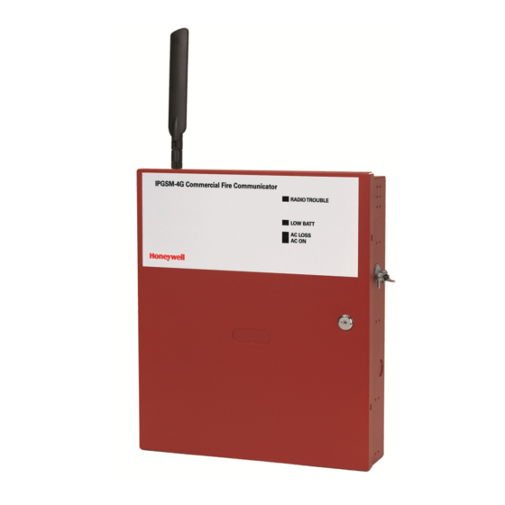
- Page 1 800-12454V2 8/14 Rev. A...
-
Page 2: Table Of Contents
Dialer Capture Module Information ....................8 LED Display Information ........................ 8 PowerBoost1 Information ......................9 Communicator Information ......................10 RF Specifications ........................11 Central Station Messages ......................11 IPGSM-4G Trouble Detection Information ..................12 IPGSM-4G Specifications ......................12 Wiring Diagram ....................Inside of Back Cover... -
Page 3: General Information
Module returns a handshake to the fire panel. The fire panel then sends the contact ID reports to the IPGSM-4G, which in turn sends a kiss-off after the report is suc- cessfully received from the fire panel. Within the IPGSM-4G, the Dialer Capture Module sends the contact ID reports over the ECP bus to the Communicator. -
Page 4: Step 1 - Activate The Sim And Setup The Customer Account
Search for the account using the Account Information or MAC ID. Under the “Actions” column, use the pull- down menu and choose Register. OR After the IPGSM-4G is installed and programmed, you can register the communicator by clicking the TEST / •... -
Page 5: Step 3 - Determine The Signal Strength And Select A Location
IPGSM-4G Commercial Fire Communicator – Installation and Setup Guide STEP 3 – Determine the Signal Strength and Select a Location IMPORTANT - Do Not mount this device outdoors. RF Exposure Warning - The internal or external antenna(s) used by this product must be installed to provide a separation distance of at least 7.8 in. - Page 6 IPGSM-4G Commercial Fire Communicator – Installation and Setup Guide Connect the LED Display board to its connector, then slide the board into the mounting rails. (Yellow LED and Buzzer are on top.) Carefully remove the packaging material that surrounds the PowerBoost1.
- Page 7 IPGSM-4G Commercial Fire Communicator – Installation and Setup Guide Wiring for Grounds, Power, and RF – 5 –...
-
Page 8: Step 5 - Program The Communicator
IPGSM-4G Commercial Fire Communicator – Installation and Setup Guide STEP 5 – Program the Communicator You must use the 7720P Programming tool to program the IPGSM-4G. When using the 7720P Programming tool, the values given below are for most installations. Press the [#] key to ac- cept the displayed default value (xxx) or enter the new value and press the [#] key for the next prompt. -
Page 9: Step 6 - Configure The Fire Panel
IPGSM-4G Commercial Fire Communicator – Installation and Setup Guide To exit the programming mode, press [N] in response to the "Review?" prompt. Then press [Y] to the "Exit Prog Mode?" prompt. Upon exiting, the root file is updated to log the changes made. A message is displayed telling the user that this step is being executed. -
Page 10: Dialer Capture Module Information
IPGSM-4G Commercial Fire Communicator – Installation and Setup Guide Dialer Capture Module Information LED Indicator STATUS RED – Steady ON Messages exist in buffer. RED – Flashing No messages to be sent. Waiting for messages. GREEN – Steady ON Normal Indication. -
Page 11: Powerboost1 Information
IPGSM-4G Commercial Fire Communicator – Installation and Setup Guide PowerBoost1 Information LED Indicator STATUS AC (green) AC power available. ACTIVE (green) Cyclical flashing – normal communications. Repetition of 3 flashes – loss of communications. LOW BATT (yellow) Missing or low battery. -
Page 12: Communicator Information
IPGSM-4G Commercial Fire Communicator – Installation and Setup Guide Communicator Information – 10 –... -
Page 13: Rf Specifications
Codes and their appropriate Restore Codes are reported to the Central Station. IPGSM-4G communicator fault – The Fire Panel sends out a E380, and E352 message via Telco #1, these are then relayed to the central station via the IPGSM-4G. -
Page 14: Ipgsm-4G Trouble Detection Information
IPGSM-4G Trouble Detection Information Telco 1 is used for the Fire Panel to output contact ID messages to the IPGSM-4G, and Telco 2 is used by the IPGSM- 4G to report faults to the Fire Panel. If Telco 1 is not operational, the Fire Panel will use Telco 2 to report events if there are no faults in the Communicator. -
Page 15: Wiring Diagram
All circuits are power limited except the backup battery which is non-power limited. • Non-power limited wiring must be separated from the power limited wiring by at least 1/4 inch. • If desired, use a Honeywell 955WH Tamper Switch with the 28-2 bracket. •... - Page 16 Contact Technical Support: (877) HPP-POWR, or Email us at hpp.techserv@honeywell.com Warranty: For the latest warranty information, please go to http://www.honeywellpower.com/warranty.html 12 Clintonville Road, Northford, CT 06472-1610 USA Ê800-12454V2?Š Copyright 2014 Honeywell International Inc. www.honeywellpower.com 800-12454V2 8/14 Rev. A...