Table of Contents
Advertisement
Quick Links
Advertisement
Table of Contents

Related Manuals for Clevo D900C


Summary of Contents for Clevo D900C
- Page 1 All manuals and user guides at all-guides.com...
- Page 2 All manuals and user guides at all-guides.com...
- Page 3 All manuals and user guides at all-guides.com Preface Notebook Computer D900C/D901C Service Manual...
- Page 4 All manuals and user guides at all-guides.com Preface Notice The company reserves the right to revise this publication or to change its contents without notice. Information contained herein is for reference only and does not constitute a commitment on the part of the manufacturer or any subsequent ven- dor.
- Page 5 This manual is intended for service personnel who have completed sufficient training to undertake the maintenance and inspection of personal computers. It is organized to allow you to look up basic information for servicing and/or upgrading components of the D900C/ D901C series notebook PC.
- Page 6 All manuals and user guides at all-guides.com Preface IMPORTANT SAFETY INSTRUCTIONS Follow basic safety precautions, including those listed below, to reduce the risk of fire, electric shock and injury to per- sons when using any electrical equipment: 1. Do not use this product near water, for example near a bath tub, wash bowl, kitchen sink or laundry tub, in a wet basement or near a swimming pool.
- Page 7 All manuals and user guides at all-guides.com Preface Instructions for Care and Operation The notebook computer is quite rugged, but it can be damaged. To prevent this, follow these suggestions: 1. Don’t drop it, or expose it to shock. If the computer falls, the case and the components could be damaged. Do not expose the computer Do not place it on an unstable Do not place anything heavy...
- Page 8 All manuals and user guides at all-guides.com Preface 4. Avoid interference. Keep the computer away from high capacity transformers, electric motors, and other strong mag- netic fields. These can hinder proper performance and damage your data. 5. Take care when using peripheral devices. Use only approved brands of Unplug the power cord before peripherals.
- Page 9 All manuals and user guides at all-guides.com Preface Battery Precautions • Only use batteries designed for this computer. The wrong battery type may explode, leak or damage the computer. • Do not continue to use a battery that has been dropped, or that appears damaged (e.g. bent or twisted) in any way. Even if the computer continues to work with a damaged battery in place, it may cause circuit damage, which may possibly result in fire.
- Page 10 All manuals and user guides at all-guides.com Preface Related Documents You may also need to consult the following manual for additional information: User’s Manual on CD This describes the notebook PC’s features and the procedures for operating the computer and its ROM-based setup pro- gram.
-
Page 11: Table Of Contents
External Locator - Front & Rear Views .........1-7 LCD (D900C/D901C) ..............A-5 External Locator - Left & Right Side View ........1-8 MB - One VGA only (D900C/D901C) ......... A-6 External Locator - Bottom View .............1-9 MB (D900C/D901C) ..............A-7 Mainboard Overview - Top (Key Parts) ........1-10 HDD (D900C/D901C) .............. - Page 12 All manuals and user guides at all-guides.com Preface DVI/ CRT ..................B-19 Panel CON/ LED Indicator ............B-20 1394/ Card Reader (TI PCI7402) ..........B-21 GLAN RTL8111B ................ B-22 Audio ALC888/ Amplifier ............B-23 KBC-H8/2111 ................B-24 JM368 PCIE to PATA ..............B-25 Mini Card &...
-
Page 13: Introduction
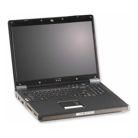
1: Introduction Overview This manual covers the information you need to service or upgrade the D900C/D901C series notebook computer. Infor- mation about operating the computer (e.g. getting started, and the Setup utility) is in the User’s Manual. Information about drivers (e.g. VGA & audio) is also found in User’s Manual. That manual is shipped with the computer. -
Page 14: System Specifications
All manuals and user guides at all-guides.com Introduction System Specifications Feature Specification Processor Types Intel® Core™ 2 Duo Processor 65nm (65 Nanometer) Process Technology LGA775 Package (775-pin) 2MB On-die L2 Cache & 1066MHz FSB E6300/ E6400 1.86/ 2.13 GHz Intel® Core™ 2 Duo Processor 65nm (65 Nanometer) Process Technology LGA775 Package (775-pin) 4MB On-die L2 Cache &... - Page 15 All manuals and user guides at all-guides.com Introduction Feature Specification Video Card NVIDIA GeForceGo 7950 GTX (G71GM-UU +MXM IV) SLI Module PCI-Express Video Card Video Card Options Note that card types, specifications and drivers Windows Vista SLI Support are subject to continual updates and changes. Check with your service center for the latest de- At the time of going to press Windows Vista did not tails on video cards supported.
- Page 16 All manuals and user guides at all-guides.com Introduction Feature Specification I/O Ports Four USB 2.0 Ports One RJ-11 Modem Jack One Mini-IEEE1394 Port One RJ-45 Gigabit LAN Jack One S-Video-Out Jack for TV & HDTV Output One DC-In Jack One DVI-Out Port (with DVI-Dual Link Support) One External Monitor Port One CATV Antenna (Analog/Digital) Jack (Functions with One Headphone/Speaker-Out Jack...
- Page 17 All manuals and user guides at all-guides.com Introduction Feature Specification Physical 397mm (w) * 298mm (d) * 51 ~ 60mm (h) 5.4kg Dimensions & Weight Optional Optical Drive Module Options: Intel PRO/Wireless 3945ABG PCIe Wireless LAN Module DVD-Super Multi Drive Module Intel PRO/Wireless 4965AGN PCIe Wireless LAN Module External USB 1.44MB Floppy Disk Drive USB 2.0 Bluetooth Class II Module...
-
Page 18: External Locator - Top View With Lcd Panel Open
All manuals and user guides at all-guides.com Introduction External Locator - Top View with LCD Panel Open Figure 1 Top View 1. Optional Built-In PC Camera 2. LCD 3. LED Power & Communication Indicators 4. Built-In Microphone 5. LED Status Indicators 6. -
Page 19: External Locator - Front & Rear Views
All manuals and user guides at all-guides.com Introduction External Locator - Front & Rear Views Figure 2 Front Views 1. LCD Latches 2. Line-In Jack 3. S/PDIF-Out Jack 4. Microphone-In Jack 5. Headphone-Out Jack 6. Speakers Figure 3 Rear Views 1. -
Page 20: External Locator - Left & Right Side View
All manuals and user guides at all-guides.com Introduction External Locator - Left & Right Side View Figure 4 Left Side View 1. External Monitor Port S-Video-Out Jack 3. Cable (CATV) Antenna Jack 4. RJ-11 Phone Jack 5. RJ-45 LAN Jack 6. -
Page 21: External Locator - Bottom View
All manuals and user guides at all-guides.com Introduction External Locator - Bottom View Figure 6 Bottom View 1. Battery (Secondary HDD Bay - HDD3) 2. Fan Outlet/Intake 3. Primary HDD Bay (HDD1 & HDD2) 4. Component Bay Cover Overheating To prevent your com- puter from overheating make sure... -
Page 22: Mainboard Overview - Top (Key Parts)
All manuals and user guides at all-guides.com Introduction Mainboard Overview - Top (Key Parts) Figure 7 Mainboard Top Key Parts 1. WLAN Module Socket 2. TV Module Socket 3. SLI Chip (BR03) 4. Northbridge (P965) 5. Southbridge (ICH8R) 1 - 10 Mainboard Overview - Top (Key Parts) -
Page 23: Mainboard Overview - Bottom (Key Parts)
All manuals and user guides at all-guides.com Introduction Mainboard Overview - Bottom (Key Parts) Figure 8 Mainboard Bottom Key Parts 1. CPU Socket (no CPU installed) 2. VGA sockets 3. Memory Slots DDR So-DIMM 4. HDD Socket 5. KBC IC (H8S/ 2111BV) 6. -
Page 24: Mainboard Overview - Top (Connectors)
All manuals and user guides at all-guides.com Introduction Mainboard Overview - Top (Connectors) Figure 9 Mainboard Top Connectors 1. CCD Cable Connector 2. LCD Connector 3. LED Connector 4. Wire Cable 2Pin Connector (M/B to MDC Module) 5. SPK 1 Connector 6. -
Page 25: Mainboard Overview - Bottom (Connectors)
All manuals and user guides at all-guides.com Introduction Mainboard Overview - Bottom (Connectors) Figure 10 Mainboard Bottom Connectors 1. CPU Fan Cable Connector 2. RAM Fan Cable Connector 3. DC-In Jack 4. DVI-Out Port 5. S-Video-In Jack 6. Serial Port 7. - Page 26 All manuals and user guides at all-guides.com Introduction 1 - 14...
-
Page 27: Disassembly
2: Disassembly Overview This chapter provides step-by-step instructions for disassembling the D900C/D901C series notebook’s parts and sub- systems. When it comes to reassembly, reverse the procedures (unless otherwise indicated). We suggest you completely review any procedure before you take the computer apart. -
Page 28: Maintenance Tools
All manuals and user guides at all-guides.com Disassembly NOTE: All disassembly procedures assume that the system is turned OFF, and disconnected from any power supply (the battery is removed too). Maintenance Tools The following tools are recommended when working on the notebook PC: •... -
Page 29: Maintenance Precautions
All manuals and user guides at all-guides.com Disassembly Maintenance Precautions The following precautions are a reminder. To avoid personal injury or damage to the computer while performing a re- moval and/or replacement job, take the following precautions: Power Safety Warning 1. -
Page 30: Disassembly Steps
All manuals and user guides at all-guides.com Disassembly Disassembly Steps The following table lists the disassembly steps, and on which page to find the related information. PLEASE PERFORM THE DISASSEMBLY STEPS IN THE ORDER INDICATED. To remove the Battery: To remove the Keyboard: 1. -
Page 31: Removing The Battery
All manuals and user guides at all-guides.com Disassembly Removing the Battery Figure 1 Battery Removal 1. Turn the computer off, and turn it over. 2. Loosen screws a. Loosen screws. 3. Release the battery. b. Release the battery. 4. Lift the battery (Figure b) out of the bay as indicated. -
Page 32: Removing The Optical (Cd/Dvd) Device
All manuals and user guides at all-guides.com Disassembly Removing the Optical (CD/DVD) Device Figure 2 Optical Device 1. Turn off the computer, and turn it over and remove the battery (page 2 - Removal 2. Locate the hard disk bay cover and remove screws , and remove the bay cover 3. -
Page 33: Removing The Hard Disk Drive
All manuals and user guides at all-guides.com Disassembly Removing the Hard Disk Drive Figure 3 The hard disk drive is mounted in a removable case and can be taken out to accommodate other 2.5" SATA hard disk HDD Assembly drives with a height of 9.5mm (h). Follow your operating system’s installation instructions, and install all necessary driv- Removal ers and utilities (as outlined in Chapter 4 of the User’s Manual) when setting up a new hard disk. - Page 34 All manuals and user guides at all-guides.com Disassembly Removing the Hard Disk(s) in the Secondary HDD Bay Figure 4 1. Turn off the computer, and turn it over and remove the battery. Secondary HDD 2. The secondary hard disk bay is located under the battery compartment. Assembly Removal 3.
-
Page 35: Removing The System Memory (Ram)
All manuals and user guides at all-guides.com Disassembly Removing the System Memory (RAM) Figure 5 RAM Module The computer has two memory sockets for 200 pin Small Outline Dual In-line Memory Modules (SO-DIMM) DDR II Removal (DDR2) supporting 533/667/800 MHz. The main memory can be expanded up to 4GB. The SO-DIMM modules sup- ported are 512MB, 1024MB and 2048MB DDR Modules. - Page 36 All manuals and user guides at all-guides.com Disassembly 6. Gently pull the two release latches & on the sides of the memory socket in the direction indicated by the Figure 6 arrows (Figure RAM Module 7. The RAM module will pop-up (Figure f), and you can then remove it.
-
Page 37: Removing The Processor
All manuals and user guides at all-guides.com Disassembly Removing the Processor Figure 7 Processor Removal 1. Turn off the computer, and turn it over, remove the battery (page 2 - 5) and RAM fan (page 2 - 2. Locate the CPU heatsink and remove screws from the heat sink in the order indicated on the label. -
Page 38: Removing The Vga Card
All manuals and user guides at all-guides.com Disassembly Removing the VGA Card Figure 8 VGA Card Removal 1. Turn off the computer, and turn it over and remove the battery (page 2 - 2. Locate the VGA bay cover and remove screws a. - Page 39 All manuals and user guides at all-guides.com Disassembly 8. Grip the handle and carefully lift the VGA card module in slot A. Figure 9 9. If two VGA cards are installed, disconnect the SLI cable from the VGA card modules. VGA Card Removal 10.
-
Page 40: Installing The Vga Card
All manuals and user guides at all-guides.com Disassembly Installing the VGA Card 1. Prepare to fit the VGA card into the slot by holding it at about a 30° angle. 2. The card needs to be fully into the slot, and the VGA card and socket have a guide-key and pin which align to allow the card to fit securely. -
Page 41: Removing The Keyboard
All manuals and user guides at all-guides.com Disassembly Removing the Keyboard Figure 11 Keyboard Removal 1. Turn off the computer, and turn it over and remove the battery (page 2 - 2. Press the four keyboard latches at the top of the keyboard to elevate the keyboard from its normal position (you a. -
Page 42: Removing The Wireless Lan Module
All manuals and user guides at all-guides.com Disassembly Removing the Wireless LAN Module Figure 12 Wireless LAN 1. Turn off the computer, and turn it over, remove the battery (page 2 - 5) and keyboard (page 2 - 15). Module Removal 2. -
Page 43: Removing The Bluetooth Module
All manuals and user guides at all-guides.com Disassembly Removing the Bluetooth Module Figure 13 Bluetooth Module 1. Turn off the computer, and turn it over, remove the battery (page 2 - 5), keyboard (page 2 - 15) and keyboard Removal shielding (page 2 - 16). -
Page 44: Removing The Modem
All manuals and user guides at all-guides.com Disassembly Removing the Modem Figure 14 Modem Removal 1. Turn off the computer, and turn it over, remove the battery (page 2 - 5), keyboard (page 2 - 15) and keyboard shielding (page 2 - 16). -
Page 45: Removing The Tv Tuner Card
All manuals and user guides at all-guides.com Disassembly Removing the TV Tuner Card Figure 15 1. Turn off the computer, and turn it over, remove the battery (page 2 - 5), keyboard (page 2 - 15) and keyboard TV Tuner Card Removal shielding (page 2 -... - Page 46 All manuals and user guides at all-guides.com Disassembly 2 - 20...
-
Page 47: Part Lists
Part Lists Appendix A:Part Lists This appendix breaks down the D900C/D901C series notebook’s construction into a series of illustrations. The compo- nent part numbers are indicated in the tables opposite the drawings. Note: This section indicates the manufacturer’s part numbers. Your organization may use a different system, so be sure to cross-check any relevant documentation. -
Page 48: Part List Illustration Location
TOP (D900C/D901C) page A - 4 BOTTOM (D900C/D901C) page A - 5 LCD (D900C/D901C) page A - 6 MB - one VGA only (D900C/D901C) page A - 7 MB (D900C/D901C) page A - 8 HDD (D900C/D901C) page A - 9... -
Page 49: Top (D900C/D901C
Figure A - 1 TOP (D900C/ D901C) 無鉛 無鉛 無鉛 無鉛 寶石藍 無鉛 無鉛 無鉛 無鉛 無鉛 無鉛 無鉛 無鉛 無鉛 無鉛 無鉛 無鉛 無鉛 無鉛 無鉛 無鉛 無鉛 無鉛 無鉛 耐熱 無鉛 寶石藍 無鉛 無鉛 無鉛 TOP (D900C/D901C) A - 3... -
Page 50: Bottom (D900C/D901C
Figure A - 2 BOTTOM (D900C/ D901C) 無鉛 無鉛 無鉛 無鉛 無鉛 無鉛 無鉛 無鉛 無鉛 無鉛 無鉛 無鉛 無鉛 無鉛 無鉛 無鉛 外 無鉛 無鉛 無鉛 無鉛 無鉛 無鉛 無鉛 無鉛 無鉛 無鉛 無鉛 A - 4 BOTTOM (D900C/D901C) -
Page 51: Lcd (D900C/D901C
無鉛 無鉛 無鉛 無鉛 無鉛 無鉛 無鉛 無鉛 無鉛 無鉛 無鉛 無鉛 無鉛 無鉛 精乘 無鉛 無鉛(增加卡勾角度) 無鉛 (黑色) 惠貿 無鉛 無鉛 (增加卡角度) 無鉛 無鉛 無鉛 無鉛 無鉛 無鉛 無鉛 無鉛 廠商改變" 無鉛 無鉛 無鉛 LCD (D900C/D901C) A - 5... -
Page 52: Mb - One Vga Only (D900C/D901C
無鉛 無鉛 無鉛 無鉛 無鉛 無鉛 無鉛 無鉛 無鉛 無鉛 無鉛 無鉛 無鉛 無鉛 無鉛 無鉛 無鉛 無鉛 無鉛 無鉛 無鉛 無鉛 無鉛 無鉛 無鉛 無鉛 無鉛 變更 無鉛 無鉛 無鉛 A - 6 MB - One VGA only (D900C/D901C) -
Page 53: Mb (D900C/D901C
藍天2 互億 無鉛 無鉛 無鉛 無鉛 無鉛 無鉛 無鉛 無鉛 無鉛 無鉛 無鉛 無鉛 無鉛 無鉛 無鉛 無鉛 無鉛 無鉛 無鉛 無鉛 無鉛 無鉛 無鉛 無鉛 無鉛 無鉛 無鉛 無鉛 無鉛 無鉛 變更 無鉛 無鉛 MB (D900C/D901C) A - 7... -
Page 54: Hdd (D900C/D901C
All manuals and user guides at all-guides.com Part Lists HDD (D900C/D901C) Figure A - 6 HDD (D900C/ D901C) 無鉛 無鉛 無鉛 A - 8 HDD (D900C/D901C) -
Page 55: 2Nd Hdd (D900C/D901C
All manuals and user guides at all-guides.com Part Lists 2nd HDD (D900C/D901C) Figure A - 7 2nd HDD (D900C/ D901C) 無鉛 無鉛 2nd HDD (D900C/D901C) A - 9... -
Page 56: Combo (D900C/D901C
All manuals and user guides at all-guides.com Part Lists COMBO (D900C/D901C) Figure A - 8 COMBO (D900C/ D901C) 無鉛 無鉛 無鉛 無鉛 無鉛 A - 10... -
Page 57: Dvd-Dual Rw (D900C/D901C
All manuals and user guides at all-guides.com Part Lists DVD-DUAL RW (D900C/D901C) Figure A - 9 DVD-DUAL RW (D900C/D901C) 無鉛 無鉛 無鉛 無鉛 無鉛 DVD-DUAL RW (D900C/D901C) A - 11... - Page 58 All manuals and user guides at all-guides.com Part Lists A - 12...
-
Page 59: Schematic Diagrams
All manuals and user guides at all-guides.com Schematic Diagrams Appendix B:Schematic Diagrams This appendix has circuit diagrams of the D900C/D901C notebook’s PCB’s. The following table indicates where to find the appropriate schematic diagram. Table B - 1 Diagram - Page... -
Page 60: Block Diagram
All manuals and user guides at all-guides.com Schematic Diagrams BLOCK DIAGRAM 15. BR03 PCI-E & STRAPS D900C BLOCK DIAGRAM CLOCK GEN ICS9LPR363 TV OUT CONROE VRD 11.0 HDTV OUT LGA 775 DAUGHTER PCI-E X 16 BOARD Sheet 1 of 40... -
Page 61: Clock Generator
All manuals and user guides at all-guides.com Schematic Diagrams CLOCK GENERATOR 3VS 6,8..1 5,17 ..22,2 4..28,31,33 CKVDD RP11 4P2R_33_04 CPUCLK0 CPUCLK VDDPCIEX CPUT_L0 CPUCLK 4 CPUCLK#0 CPUCLK# HCB2012KF-121T30 VDDPCIEX CPUC_L0 CPUCLK# 4 C159 C161 C167 C187 C172 C183 C182 VDDPCIEX CPUCLK1 MCHCLK MCHCLK 5... - Page 62 All manuals and user guides at all-guides.com Schematic Diagrams CPU-1 VCORE VCORE U19A CPU_A#[3..16] CPU_D#[0..15] 5 U19C CPU_A#3 CPU_D#0 A03# D00# CPU_A#4 CPU_D#1 AH18 A04# D01# CPU_A#5 CPU_D#2 VCORE VCORE AH19 A05# D02# CPU_A#6 CPU_D#3 AC23 AH21 A06# D03# U19D CPU_A#7 CPU_D#4 AC24...
- Page 63 All manuals and user guides at all-guides.com Schematic Diagrams CPU-2 CPU_VIDSEL 34 U19B VCCA_VSSA_VCOREPLL Trace w idth done sn't le ss than 12 Mil CPU_SMI# TESTH I_0 47_04 1.2VS CPU_SMI# SMI# TESTHI00 U19E U19F As close a s possible to CPU socke t CPU_A20M# TESTH I_1 47_04...
-
Page 64: Intel P965 Cpu Interface 1/4
All manuals and user guides at all-guides.com Schematic Diagrams Intel P965 CPU Interface 1/4 1.2VS 1.2VS 4,6,9,12,15..17,30 CPU_D#[0..63] CPU_A#[3..35] CPU_D#[0..63] 3 CPU_A#[3..35] CPU_A#3 CPU_D#0 HA3# CPU_A#4 CPU_D#1 HA4# CPU_A#5 CPU_D#2 HA5# CPU_A#6 CPU_D#3 BC37 HA6# VSS_1 VSS_229 CPU_A#7 CPU_D#4 BC32 HA7# VSS_2 VSS_228... -
Page 65: Intel P965 Pci- E I
All manuals and user guides at all-guides.com Schematic Diagrams Intel P965 PCI- E I/F 2/4 PE0_RX[0..15] DMI_RX[0..3] PE0_RX[0..15] 15 DMI_RX[0..3] 10 PE0_RX#[0..15] DMI_RX#[0..3] PE0_RX#[0..15] 15 DMI_RX#[0..3] 10 PE0_TXC[0..15] DMI_TX[0..3] PE0_TXC[0..15] 15 DMI_TX[0..3] 10 PE0_TXC#[0..15] DMI_TX#[0..3] R797 39_04(R) DAC_HSY NC PE0_TXC#[0..15] 15 DMI_TX#[0..3] 10 D AC_H SY NC 18 R798... -
Page 66: Intel P965 Memory I
All manuals and user guides at all-guides.com Schematic Diagrams Intel P965 Memory I/F 3/4 MEM_0_DATA[0..63] MEM_0_DQM[0..7] MEM_1_DATA[0..63] MEM_1_DQM[0..7] MEM_0_DATA[0..63] MEM_0_DQM[0..7] MEM_1_DATA[0..63] MEM_1_DQM[0..7] MEM_0A_ADD[0..14] MEM_0_DQS[0..7] MEM_0B_ADD[0..14] MEM_1_DQS[0..7] MEM_0A_ADD[0..14] MEM_0_DQS[0..7] MEM_0B_ADD[0..14] MEM_1_DQS[0..7] MEM_0_DQS#[0..7] MEM_1_DQS#[0..7] MEM_0_DQS#[0..7] MEM_1_DQS#[0..7] 0.9VS MEM_0A_ADD0 MEM_0_DQS0 MEM_0B_ADD0 MEM_1_DQS0 BA31 BB17 SMA_A0 SDQS_A0... -
Page 67: Ddrii Sodimm
All manuals and user guides at all-guides.com Schematic Diagrams DDRII SODIMM 1.8V 1.8V C475 C477 C479 C480 C101 C111 C476 C478 C117 C100 C112 MEM_0_D ATA[ 0..63] .1U_X7R_04 .1U_X7R_04 .1U_X7R_04 10U/10V_08 10U/10V_08 MEM_0_DATA[0..63] MEM_0A_AD D[0.. 14] .1U_X7R_04 .1U_X7R_04 .1U_X7R_04 10U/10V_08 220U/4V_D2(R) MEM_1_DATA[0. -
Page 68: Intel P965 Power 4/4
All manuals and user guides at all-guides.com Schematic Diagrams Intel P965 Power 4/4 1.25VS V_CKDDR VCCA_DAC HCB2012KF-121T30 1.2VS 1.25VS C174 C175 C163 .1U_X7R_04 10U/10V_08 AG25 .1U_X7R_04 VTT_1 VCC_81 AG24 VTT_2 VCC_172 AG23 VTT_3 VCC_173 AG22 VTT_4 VCC_174 AG21 VTT_5 VCC_82 V_CKDDR HCB2012KF-121T30 AG20... -
Page 69: Ich8 Pci, Dmi, Cpu, Irq
All manuals and user guides at all-guides.com Schematic Diagrams ICH8 PCI, DMI, CPU, IRQ 3VS 2,6,8,9,11..15,17..22,24..28,31,33 DMI_RX[0..3] DMI_RX[0..3] 6 DMI_RX#[0..3] DMI_RX#[0..3] 6 3V 4,6,11..13,21,25..28,30..33 DMI_TX[0..3] DMI_TX[0..3] 6 RP20 DMI_TX#[0..3] DMI_TX#[0..3] 6 1.5VS 1.5VS 4,9,11..13,25,28,33 RP27 INT#D PR EQ#0 INT#B 5VS 6,12..14,18,19,22,24,26..28,33 PR EQ#3 INT#C DEVSEL#... -
Page 70: Ich8 Lpc, Ata, Usb, Gpio
All manuals and user guides at all-guides.com Schematic Diagrams ICH8 LPC, ATA, USB, GPIO R351 10K_04 3V 4,6,10,12,13,21,25..28,30..33 3VS 2,6,8..10,12..15,17..22,24..28,31,33 GATERST# PCIRST# VDD3 VDD3 4,13,19,23,25..27,29,32,33 20,21 GATERST# PCIRST# 10,20,23,28 2N7002W 1.5VS 1.5VS 4,9,10,12,13,25,28,33 GATE_PCIRST# LPC_AD0 SATA_RX#0 23,25 LPC_AD0 SATA_RX#0 27 LAD0 SATA_0RXN LPC_AD1... -
Page 71: Ich8 Power
All manuals and user guides at all-guides.com Schematic Diagrams ICH8 Power 5VREF & 5VREF_SUS Sequencing Circuit ICH8R 82801HR 5VR EF C594 .1U_X7R_04 V5REF VCCLAN1_05 2N3904 VCCLAN1_05 5VR EF _SUS V5REF_SUS C598 .1U_X7R_04 1.5VS VCC1_5_A VCC1_5_A 1.5VS R560 10_06 5VR EF VCC1_5_A VCC1_5_A C582... -
Page 72: Mxm Pci-E Con1
All manuals and user guides at all-guides.com Schematic Diagrams MXM PCI-E CON1 VIN 19,26,29..34 J_MXM2 1.8VS 1.8VS 14,33 5VS 6,12,14,18,19,22,24,26..28,33 MXM_VIN 1.8VS 3.5A 3VS 2,6,8..12,14,15,17..22,24..28,31,33 PWR_SRC 1V8RUN 2.5VS 2.5VS 14,31 PWR_SRC 1V8RUN 1.5VS 1.5VS 4,9..12,25,28,33 PWR_SRC 1V8RUN VDD3 VDD3 4,19,23,25..27,29,32,33 PWR_SRC 1V8RUN 3V 4,6,10..12,21,25..28,30..33... -
Page 73: Mxm Pci-E Con2
All manuals and user guides at all-guides.com Schematic Diagrams MXM PCI-E CON2 1.8VS 1.8VS 13,33 3VS 2,6,8..13,15,17..22,24..28,31,33 5VS 6,12,13,18,19,22,24,26..28,33 2.5VS 2.5VS 13,31 MXM_VIN MXM_VIN 13 J_MXM1 MXM_VIN 3.5A PW R_SRC 1V8RUN 1.8VS PW R_SRC 1V8RUN PEX_D0_RX#[0..15] PW R_SRC 1V8RUN PEX_D0_RX#[0..15] PW R_SRC 1V8RUN PEX_D0_RX[0..15]... -
Page 74: Br03 Pci-E & Straps 1/3
All manuals and user guides at all-guides.com Schematic Diagrams BR03 PCI-E & Straps 1/3 PE0_RX[0..15] PE0_RX[0..15] 6 4..6,9,12,16,17,30 1.2VS 1.2VS PE0_RX#[0..15] PE0_RX#[0..15] 6 PE0_TXC[0..15] PE0_TXC[0..15] 6 2,6,8..14,17..22,24..28,31,33 PE0_TXC#[0..15] PE0_TXC#[0..15] 6 U42A 3 VS PE0_RX0 C923 .1U_X7R_04 Z1501 Z1533 PE0_RX#0 UP0_PEX_TX0 NPX_TX0 C927 .1U_X7R_04... -
Page 75: Br03 Pci-E Interface 2/3
All manuals and user guides at all-guides.com Schematic Diagrams BR03 PCI-E Interface 2/3 PEX_D0_RX#[0..15] PEX_D0_TX#[0..15] U42C PEX_D0_RX#[0..15] PEX_D0_TX#[0..15] PEX_D0_RX[0..15] PEX_D0_TX[0..15] PEX_D1_RST# PEX_D0_RX[0..15] PEX_D0_TX[0..15] PEX1_RES ET# PEX_D1_RST# 13 U42B PEX_D1_RX0 PEX_D0_RST# DP1_PEX_RX0 PEX_D1_RX#0 PEX_D0_RST# 14 P EX0_RES ET# DP1_PE X_RX0# PEX_D1_TX0 PEX_D0_RX0 C219 .1U_X7R_04... -
Page 76: Br03 Power & Gnd 3/3
All manuals and user guides at all-guides.com Schematic Diagrams BR03 Power & GND 3/3 4..6,9,12,15,16,30 1.2VS 1.2VS 1.2V S 2,6,8..15,18..22,24..28,31,33 BR03VDD U42D 1.2VS 1.2VS C950 C952 C960 C954 C963 C951 C962 C957 10U/10V_08 10U/10V_08 10U/10V_08 10U/10V_08 10U/10V_08 10U/10V_08 10U/10V_08 10U/10V_08 AD14 AE14 1.2VS... -
Page 77: Dvi/ Crt
All manuals and user guides at all-guides.com Schematic Diagrams DVI/ CRT Close to DVI PORT DVI PORT SCS751V-40 C140 10P/50V_04(R) J_DVI1 TXN2 0_04 TXN2 CASE TXP2 R100 0_04 TXP2 CASE C141 10P/50V_04(R) TMDS DATA 2- 10P/50V_04(R) TMDS DATA 2+ TXUP1# 0_04 TXUP1# TMDS 2/4 Shield... -
Page 78: Panel Con/ Led Indicator
All manuals and user guides at all-guides.com Schematic Diagrams Panel CON/ LED Indicator LCDVCC LCDVCC HCB2012KF-121T30 HCB2012KF-121T30 C342 C339 JLCD1 .1U_04 .1U_04 T XOUT -LN0 T XOUT -UN0 R323 T XOUT -LP 0 T XOUT -UP 0 0_04 60 mil LCDVCC T XOUT -LN1 T XOUT -UN1... -
Page 79: 1394/ Card Reader (Ti Pci7402
All manuals and user guides at all-guides.com Schematic Diagrams 1394/ Card Reader (TI PCI7402) AD[0..31] 10,28 AD[0..31] C789 C816 C832 C790 C819 C784 AD31 AD31 CCLK AD30 AD30 CAUDIO .01U_04 .1U/16V_04 10U/10V_08 AD29 AD29 CSTSCHG .1U/16V_04 10U/10V_08 AD28 AD28 CPAR .1U/16V_04 AD27 AD27... -
Page 80: Glan Rtl8111B
All manuals and user guides at all-guides.com Schematic Diagrams GLAN RTL8111B CTRL18 LAN_V DD3 LANVDD18 2SB1188 40 mil 40 mil FCM2012VF-121T08 C821 C809 C818 C802 C791 C827 C835 C830 C836 10U/10V_08 .1U_04 .1U_04 10U/10V _08 100U/6.3V_B 10U/10V_08 .1U_04 .1U_04 .1U_04 LAN_AVDD3 LANVDD15 CTRL15... -
Page 81: Audio Alc888/ Amplifier
All manuals and user guides at all-guides.com Schematic Diagrams Audio ALC888/ Amplifier HCB2012KF-121T30(R) 3VS 2,6,8..15,17..21,24..28,31,33 Power Plane HCB2012KF-121T30 5VS 6,12..14,18,19,24,26..28,33 VDDAC C763 C749 R608 C712 C703 C722 C699 VDDAC VOUT 10U/10V_08 .1U_04 .1U_04 10U/ 10V_08 AMP_MUTE R596 100K_04 R594 120K_04 0_04 10U/10V_08 .1U_04... -
Page 82: Kbc-H8/2111
All manuals and user guides at all-guides.com Schematic Diagrams KBC-H8/2111 R674 10K_04 MD0_BOOT_FLASH JH8DBG VDD3 KBC_VDD VDD5 KBC_VDD VDD3 R598 10K_04 24 mil R595 VDD5 VDD3 10K_04 VDD3 FCM2012V-121_08(R) AUX_CLK R640 10K_04 C681 C677 JH8DBG1 AUX_DATA R642 10K_04 C683 2N7002W R659 MD0_BOOT_FLASH KBD_CLK... -
Page 83: Jm368 Pcie To Pata
All manuals and user guides at all-guides.com Schematic Diagrams JM368 PCIE to PATA CM1117 DVDD1.8 VOUT DVDD1.8 3VS 2,6,8..15,17..22,25..28,31,33 C974 C973 DVDD1.8 C975 3V 4,6,10..13,21,25..28,30..33 .1U/16V_04 R804 100U/6.3V_B(R) .1U/16V_04 5VS 6,12..14,18,19,22,26..28,33 220_04 R803 100_04 DVDD1.8 ZGPIO3 ASTXP0 PLTRST# 6,10,15,28 PLTRST# YROMCSn ASTXN0 PH_DMACK#... -
Page 84: Mini Card & Tv Out/ Video In
All manuals and user guides at all-guides.com Schematic Diagrams Mini Card & TV Out/ Video In MINI CARD for WAN 1.5VS 1.5VS 4,9..13,28,33 3VS 2,6,8..15,17..22,24,26..28,31,33 TV OUT FILTER 1.5VS 1.5VS 4,9..13,28,33 3V 4,6,10..13,21,26..28,30..33 VDD3 4,13,19,23,26,27,29,32,33 VDD3 JMINI1 C457 11,13,21,28 PE_WAKE# WAKE# 3.3V_0 BT_DATA... -
Page 85: Daughter Connection
All manuals and user guides at all-guides.com Schematic Diagrams Daughter Connection VIN 13,19,29..34 PHONE JACK BOARD VDD5 VDD5 19,23,30,31,33 SWITCH BOARD 5VS 6,12..14,18,19,22,24,27,28,33 3V 4,6,10..13,21,25,27,28,30..33 J_SW1 3VS 2,6,8..15,17..22,24,25,27,28,31,33 PWRS PWRS VDD3 VDD3 4,13,19,23,25,27,29,32,33 J_AUDIO1 LID_SW# 19,23 LID_SW# WEB0# WEB0# 5V 12,13,23,27,30..34 VDD5 WEB1# WEB1#... -
Page 86: Ccd/ Bt/ Fan/ Rom
All manuals and user guides at all-guides.com Schematic Diagrams CCD/ BT/ FAN/ ROM J_BT1 Bluetooth 3V_BT D05A JBT1 WCM3216F2S-161T03 5V_CCD +3.3v HCB2012KF-121T30 48 mil USBN1 USBN1 USB- USBP1 USBP1 USB+ BT_DET# BT_DET# DETECT# AO3409 J_CCD1 R433 10K_04 VDD3 R359 330K_04 85205-0500 BT_EN# BT_ON#... -
Page 87: Mini Pci/ Mdc/ New Card
All manuals and user guides at all-guides.com Schematic Diagrams Mini PCI/ MDC/ New Card Svideo_C Svideo_C 25 1.5VS 1.5VS 4,9..13,25,33 Svideo_Y Svideo_Y 25 5VS 6,12..14,18,19,22,24,26,27,33 AD[0:31] AD[0:31] 10,20 3VS 2,6,8..15,17..22,24..27,31,33 CIR_RX CIR_RX_M 23,26 CIR_RX CIR_RX_M 25 3V 4,6,10..13,21,25..27,30..33 1SS355 R364 10K_04 JMINIPCI1 C398... -
Page 88: Ac-In, Charger
All manuals and user guides at all-guides.com Schematic Diagrams AC-In, Charger PD22 *SBM1040 VIN 13,19,26,30..34 AM4835P VDD3 VDD3 4,13,19,23,25..27,32,33 AM4835P Charge Current 3.2A VA 32 Charge Voltage 16.8V AM4835P Total Power 255W PR18 10m_25 JAC1 SI4800BDY HCB4532KF-800T60 4.7U_7*7*3.5 AM4835P PR19 10m_25 HCB4532KF-800T60 AC5V_IN... -
Page 89: Power 1.2V/ 1.25V
All manuals and user guides at all-guides.com Schematic Diagrams Power 1.2V/ 1.25V VIN 13,19,26,29,31..34 3V 4,6,10..13,21,25..28,31..33 5V 12,13,23,26,27,31..34 VDD5 VDD5 19,23,26,31,33 1.25VS 1.25VS 6,9,12 1.2VS 1.2VS 4..6,9,12,15..17 V1.2 V1.2 34 PC174 1U_10V_06 PR168 0_06 PR156 10_04 VDD5 PC186 1U_10V_06 PR165 10K_04 PR166 10_04... -
Page 90: Power 1.5V/ 1.05V/ 2.5V
All manuals and user guides at all-guides.com Schematic Diagrams Power 1.5V/ 1.05V/ 2.5V 2,6,8..15,17..22,24..28,33 19,23,26,30,33 VDD5 VDD5 13,19,26,29,30,32..34 12,13,23,26,27,30,32..34 4,6,10..13,21,25..28,30,32,33 1.05VS 1.05VS 1.5V 1.5V 13,14 2.5VS 2.5VS PC118 1U_10V_06 PR120 0_06 PR112 10_04 VDD5 PC131 1U_10V_06 PR122 10_04 PR123 10K_04 PD16 PD19 SGND1... -
Page 91: Power 1.8V/ 0.9V/ 12V
All manuals and user guides at all-guides.com Schematic Diagrams Power 1.8V/ 0.9V/ 12V 3V 4,6,10..13,21,25..28,30,31,33 5V 12,13,23,26,27,30,31,33,34 V1.8 VIN 13,19,26,29..31,33,34 VA 29 PR67 PR70 VDD3 VDD3 4,13,19,23,25..27,29,33 PR148 1.5M_06 10_06 100K_04 1.8V 1.8V 7..9,33 FM0540-N 0.9VS 0.9VS 7 PR150 10_06 1.8V_PWRGD VDDQS 1 2 V 1 9 ,3 4... -
Page 92: Power 3.3V/ 5V
All manuals and user guides at all-guides.com Schematic Diagrams Power 3.3V/ 5V VDD5 VDD5 19,23,26,30,31 1.5VS 1.5VS 4,9..13,25,28 3V 4,6,10..13,21,25..28,30..32 5VS 6,12..14,18,19,22,24,26..28 VIN 13,19,26,29..32,34 3VS 2,6,8..15,17..22,24..28,31 5V 12,13,23,26,27,30..32,34 1.8V 1.8V 7..9,32 VDD3 VDD3 4,13,19,23,25..27,29,32 1.5V 1.5V 31 PQ21 1.8VS 1.8VS 13,14 SI4800BDY VDD5 RUN/SS2... -
Page 93: Vcore Power
All manuals and user guides at all-guides.com Schematic Diagrams VCore Power VTT_OUT_RIGHT VTT_OR 3,4 13,19,26,29..33 V1.2 V1.2 30 V1.2 12,13,23,26,27,30..33 4..6,9,12,15..17,30 1.2VS 1.2VS VCORE VCORE 40mil VTT_OUT_RIGHT VTT_OUT_RIGHT VTT_OUT_RIGHT 19,32 PR16 40mil 2.2_06 PD20 FM0540-N PC138 PC137 PR127 0_06 PC16 PC23 PC141 10U_25V_12... -
Page 94: Audio Board
All manuals and user guides at all-guides.com Schematic Diagrams Audio Board AJAUDIO4 LINE IN LINE_SENSE_A LINE-R_A HCB2012KF-121T30 (SURR) AJADJ1 LINE-L_A HCB2012KF-121T30 VDD5_A 2SJ-S870-010 BLUE CIR_RX_A 330P 330P LINE-R_A LINE-L_A A_AGND AJAUDIO3 SPDIF-OUT_A SPDIF MIC1_R_A MIC1_L_A SPDIF-OUT_A FCM1608K-121T06 JD_SENSE_A 2SJ-S870-010 AMP_MUTE_A BLACK MSPKR_A 680P... -
Page 95: Card Reader Board
All manuals and user guides at all-guides.com Schematic Diagrams Card Reader Board VCC_CARD BJ_CR1 Card Reader Power SD_CD#_B CD_SD SD_WP_B W P_SD 3VS_B VCC_CARD VDD_SD CLK_SD CLK_SD_B AO3409 CLK_MS MS_BS/SD_CMD_B 60 mil VCC_MS CMD_SD BS_MS MS/SD_D0_B DAT0_SD MS/SD_D1_B 10U/10V_08 VSS_SD DAT0_MS 100K_04 100K_04... -
Page 96: Click Board
All manuals and user guides at all-guides.com Schematic Diagrams Click Board VCC5_C VCC5_C 10K_04 10K_04 VCN2 VCN1 10MIL TPADDATA_C 10MIL TPADDATA_C TPADCLK_C TPADCLK_C 85202-0405 10MIL .1U_06 SW_L 0_04(R) 120P SW_R 120P 120P 8 71 52 -12 07 GND_C plan GND_C Sheet 37 of 40 Click Board VCC5_C... -
Page 97: Hotkey Board
All manuals and user guides at all-guides.com Schematic Diagrams HotKey Board DWEB1 HOT KEY1#_D HCH STS-05-A GND_D DJ_KEY1 HOT KEY1#_D HOT KEY2#_D DSW EB1 85202-0405 HOT KEY2#_D GND_D HCH STS-05-A GND_D Sheet 38 of 40 HotKey Board SPI_TOOL1 SXUAZ-10S2-B PLACE TOP SIDE SPI_TOOL2 (Hotkey Board) H6_0D2_3... -
Page 98: Switch Board
All manuals and user guides at all-guides.com Schematic Diagrams Switch Board VIN_E SCRO LLOCK_1 220_08 EJSW1 SML-010MTT86 CA P SLO CK _1 PWRS_1 220_08 LID_SW#_1 WEB0#_1 SML-010MTT86 WEB1#_1 NU M LOCK_1 WEB2#_1 220_08 +3V_E +3VS_E SML-010MTT86 SCROLLOCK_1 CAPSLOCK_1 2 2 0 _ 0 8 NUMLOCK_1 2N3906 CR_ LED_1 #... -
Page 99: Usb Board
All manuals and user guides at all-guides.com Schematic Diagrams USB Board 60 mil 60 mil EMI solution,when placement EMI solution,when placement near to USB Port? near to USB Port? FJ_USB2 FJ_USB3 HCB2012KF-121T30 HCB2012KF-121T30 USBVCC1 VCC0 USBVCC2 VCC0 60 mil 60 mil DATA0- DATA0- DATA0+... - Page 100 All manuals and user guides at all-guides.com Schematic Diagrams B - 42...