Table of Contents
Advertisement
Quick Links
All manuals and user guides at all-guides.com
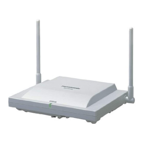
2-Channel Cell Station Unit for DECT Portable Station
KX-TDA0155CE
(for Europe, Asia Oceania,
Middle Near East, Russia and Africa)
© Panasonic System Networks Co., Ltd. 2010
Unauthorized copying and distribution is a violation
of law.
ORDER NO. KMS1005777CE
Advertisement
Table of Contents

Related Manuals for Panasonic KX-TDA0155CE


Summary of Contents for Panasonic KX-TDA0155CE
- Page 1 All manuals and user guides at all-guides.com ORDER NO. KMS1005777CE 2-Channel Cell Station Unit for DECT Portable Station KX-TDA0155CE (for Europe, Asia Oceania, Middle Near East, Russia and Africa) © Panasonic System Networks Co., Ltd. 2010 Unauthorized copying and distribution is a violation of law.
-
Page 2: Table Of Contents
All manuals and user guides at all-guides.com KX-TDA0155CE TABLE OF CONTENTS PAGE PAGE 1 Safety Precautions -----------------------------------------------3 1.1. For Service Technicians ----------------------------------3 1.2. Caution--------------------------------------------------------3 2 Warning --------------------------------------------------------------3 2.1. About Lead Free Solder (PbF: Pb free) --------------3 2.2. Discarding of P. C. Board --------------------------------4... -
Page 3: Safety Precautions
All manuals and user guides at all-guides.com KX-TDA0155CE 1 Safety Precautions 1.1. For Service Technicians • Repair service shall be provided in accordance with repair technology information such as service manual so as to pre- vent fires, injury or electric shock, which can be caused by improper repair work. -
Page 4: Discarding Of P. C. Board
All manuals and user guides at all-guides.com KX-TDA0155CE 2.1.1. Suggested PbF Solder There are several types of PbF solder available commercially. While this product is manufactured using Tin, Silver, and Copper, (Sn+Ag+Cu), you can also use Tin and Copper, (Sn+Cu), or Tin, Zinc, and Bismuth, (Sn+Zn+Bi). Please check the manufac turer's specific instructions for the melting points of their products and any precautions for using their product with other materials. -
Page 5: Technical Descriptions
All manuals and user guides at all-guides.com KX-TDA0155CE 4 Technical Descriptions 4.1. Block Diagram 4.1.1. Main Board... -
Page 6: Hardware Description
Function Description KX-TDA0155CE is the Cell Station (CS) for TDA and TDE and NCP series. CS converts voice data from PBX to radio signal and transmits to Portable Station (PS). Conversely CS converts radio signal from PS to voice data and transmits to PBX. - Page 7 All manuals and user guides at all-guides.com KX-TDA0155CE 4.2.1.4. FPGA FPGA (IC103) has the following features. (1) ST-BUS I/F, BBIC PCM I/F Extracts voice data from ST-BUS digital data and changes format to BBIC PCM format, then provides it to BBIC(IC100).
- Page 8 All manuals and user guides at all-guides.com KX-TDA0155CE 4.2.1.6. Power Supply Circuit PAV3.3V, RF2.5V, 3.2V, 1.8V, RF1.8V, 1.5V and 5.25V are generated in CS. 5.5V is output of DC/DC Convertor. Other power supplies are made from 5.25V. PAV3.3V and RF2.5V are the power supply for RF block. 3.2V is the power supply for logic circuit.
-
Page 9: Installation Instructions
All manuals and user guides at all-guides.com KX-TDA0155CE 5 Installation Instructions 5.1. Connecting the Cell Station to the Hybrid IP-PBX KX-TDA0155 connecting to KX-TDA100/KX-TDA200/KX-TDA600/KX-TDE100/KX-TDE200/KX-TDE600 Note The illustration of the PBX is based on the KX-TDE200. Accessories and User-supplied Items for the CS... - Page 10 All manuals and user guides at all-guides.com KX-TDA0155CE KX-TDA0155 connecting to KX-NCP500/KX-NCP1000 Note The illustration of the PBX is based on the KX-NCP500. Accessories and User-supplied Items for the CS Accessories (included): Screws x 2, Washers x 2 User-supplied (not included): RJ11 connector Note For details about the DHLC/DLC card, refer to the Installation Manual for your PBX.
-
Page 11: Connectiong The Cs
All manuals and user guides at all-guides.com KX-TDA0155CE 5.2. Connectiong the CS 1. Connect the cable from CSIF card to the CS. 2. Pass the cable through the groove of the CS (in any direction depending on your preference). -
Page 12: Test Mode
All manuals and user guides at all-guides.com KX-TDA0155CE 6 Test Mode 6.1. Required Equipment 1. Personal Computer with serial port. 2. Servuce Jig cable (PSZZ2CA155EU) 3. TEL cord 4. Power Supply Adaptor (PSZZ1TDA0142) 5. AC Adaptor (KX-TCA1 / KX-A11 / PSLP1434) 6. -
Page 13: Command Reference
All manuals and user guides at all-guides.com KX-TDA0155CE 4. Set communication environment Click “Config” and configure as follows: Click “OK”. Selected items will be stored. 6.3. Command Reference 6.3.1. Select From Command Menu - Example of Operation - 1. Click [test command] tag... - Page 14 All manuals and user guides at all-guides.com KX-TDA0155CE 2. Click [ Command menu ] button and select the command that you want execute. (in case of test command "VDD") 3. Set parameters if necessary.
- Page 15 All manuals and user guides at all-guides.com KX-TDA0155CE 4. Click [send] button. Maintenance Window is generated, and transmitted command and parameters are displayed. Then receive data from TDA0155CE is displayed. - Operation of each test command - A) Test Command "VDD control (VDD)"...
- Page 16 All manuals and user guides at all-guides.com KX-TDA0155CE D) Test Command "RFPI write (RFW)" 1. Click [ Command menu ] button. 2. Point [ RF ]. 3. Click [ RFPI write (RFW) ]. 4. Set ID (5 byte) to the first parameter 5.
- Page 17 All manuals and user guides at all-guides.com KX-TDA0155CE 6.3.2. Input The Command Directly Menu - Example of Operation - 1. Click [test command] tag. 2. Input the command and parameter (if necessary) directly to the [command] box. (Don't set paramter to the [parameter] box. )
- Page 18 All manuals and user guides at all-guides.com KX-TDA0155CE 3. Click [send] button. Maintenance Window is generated, and transmitted command and parameters are displayed. Then receive data from TDA0155CE is displayed. note: When you overwrite the command used last time and input a new command, it is no problem though parameter of old command...
-
Page 19: Troubleshooting Guide
All manuals and user guides at all-guides.com KX-TDA0155CE 7 Troubleshooting Guide 7.1. Portable Station (PS) Cannot Register to Cell Station (CS) or PS Does not Link CS. - Page 20 All manuals and user guides at all-guides.com KX-TDA0155CE...
-
Page 21: Disassembly And Assembly Instructions
All manuals and user guides at all-guides.com KX-TDA0155CE 8 Disassembly and Assembly Instructions 8.1. Disassembly Instructions 1. Remove the five screws (A), and remove the Bottom Cabinet. 2. Remove the Solder on Cable of the Main Board by the Soldering iron. -
Page 22: Measurements And Adjustments
All manuals and user guides at all-guides.com KX-TDA0155CE 9 Measurements and Adjustments 9.1. Version Check and CSID Writing 9.1.1. Required Equipment 1. (PC)Personal Computer with serial port (Windows 2000/98 or previous version) 2. Power supply adaptor (PSZZ1TDA0142) 3. Service JIG cable (PSZZ2CA155EU) 4. - Page 23 All manuals and user guides at all-guides.com KX-TDA0155CE 9.1.3. Version check Text following “Command:” is the input command for the terminal connected to the CS. Text following “Response:” is the terminal display response data. Confirm the response before proceeding to the next step.If no response is set. shot off power and repeat from the beginning.
-
Page 24: Adjustment For Main Part
All manuals and user guides at all-guides.com KX-TDA0155CE 9.2. Adjustment for Main Part 9.2.1. Required Equipment 1. Tester 2. Frequency counter 3. (PC)Personal Computer with serial port (Windows 2000/98 or previous version) 4. Power supply adaptor (PSZZ1TDA0142) 5. Service JIG cable (PSZZ2CA155EU) 6. - Page 25 All manuals and user guides at all-guides.com KX-TDA0155CE 9.2.3. Adjustment for 1.8V Description of 1.8V calibration process Text following “Command:” is the input command for the terminal connected to the CS. Text following “Response:” is the terminal display response data.
-
Page 26: Measurement And Adjustment For Rf Part
All manuals and user guides at all-guides.com KX-TDA0155CE 9.3. Measurement and Adjustment for RF Part Note: About the software version Update the software to the latest version before performing the RF test. 9.3.1. Required Equipment 1. CMD60 2. (PC) Personal Computer with serial port (Windows2000/98 or previous version with communication software) 3. - Page 27 All manuals and user guides at all-guides.com KX-TDA0155CE 9.3.2.2. RF Test 1. Set the CMD60 to MANUAL TEST. 2. Set the CMD60 TRAFFIC CARRIER to 5. 3. Press ACCEPT RFPI and SETUP CONNECT on the CMD60. 4. Check Power (NTP) : must be +20 to +24dBm 5.
- Page 28 All manuals and user guides at all-guides.com KX-TDA0155CE serial port setup check next check boxes ASCII Receiving - Append line feeds to incoming line ends Warp lines that exceed terminal width 10. Supply a voltage to the TEL jack from the AC adaptor (KX-TCA1 / KX-A11 / PSLP1434) via power supply adaptor (PSZZ1TDA0142) 9.3.3.2.
- Page 29 All manuals and user guides at all-guides.com KX-TDA0155CE 7. Connect the PC to the CS by service JIG cable 8. Start up the PC and start the hyper terminal 9. Set the hyper terminal property as follows serial port setup...
-
Page 30: Miscellaneous
All manuals and user guides at all-guides.com KX-TDA0155CE 10 Miscellaneous 10.1. Terminal guide of ICs, Transistors and Diodes... -
Page 31: How To Replace A Flat Package Ic
All manuals and user guides at all-guides.com KX-TDA0155CE 10.2. How To Replace a Flat Package IC Even if you do not have the special tools (for example, a spot heater) to remove the Flat IC, with some solder (large amount), a sol- dering iron and a cutter knife, you can easily remove the ICs that have more than 100 pins. -
Page 32: How To Replace The Llp (Leadless Leadframe Package) Ic And Ic Ground Plate
All manuals and user guides at all-guides.com KX-TDA0155CE 10.3. How to Replace the LLP (Leadless Leadframe Package) IC and IC ground plate 10.3.1. Preparation • PbF (: Pb free) Solder • Soldering Iron Tip Temperature of 700 °F ± 20 °F (370 °C ± 10 °C) Note: We recommend a 30 to 40 Watt soldering iron. - Page 33 All manuals and user guides at all-guides.com KX-TDA0155CE 10.3.5. How to Remove a Solder Bridge (Doesn't apply to IC ground plate.) When a Solder Bridge is found after soldering the bottom of the IC, remove it with a soldering iron.
-
Page 34: Schematic Diagram
All manuals and user guides at all-guides.com KX-TDA0155CE 11 Schematic Diagram 11.1. Main Board 1608 RFCLK TP452 0.47uH RFCLK 85 DAB4 L600 D[4] TP451 VSS17 470p 86 DAB12 D[12] TP450 VDD16 87 DAB5 C441 D[5] TP449 P3[2]/PD2 C436 88 DAB13... - Page 35 All manuals and user guides at all-guides.com KX-TDA0155CE C332 C331 1.0u C330 1.0u R345 R357 R314 2.5V0.7F 2.5V0.7F 2.5V0.7F R309 C339 C340 PDADIN C341 1/2W,120 R341 R313 100K 100K 100K R359 R358 R360 FTC_PW FSTC_POW R329 0.01u C309 470u C308...
- Page 36 All manuals and user guides at all-guides.com KX-TDA0155CE R808 R836 2125 R828 C953 C952 L913 L914 R827 R822 39nH 39nH R821 L912 L911 R820 R819 RA108 39nH L910 L909 R936 1 GND1 GND26 2 ANT2 TXPO-SET 3 VCCPA GND24 4 GND4...
- Page 37 All manuals and user guides at all-guides.com KX-TDA0155CE C251 470P C250 0.01u C225 0.01u C224 D117 D118 470P C249 470P C248 0.01u C223 470P C222 0.01u 51 GND51 GND25 52 VPUMP VMV1 VPUMP TP269 53 NC53 A[21] 54 TD0 R236...
-
Page 38: Waveform
All manuals and user guides at all-guides.com KX-TDA0155CE 11.2. Waveform Reset signal (start up) IC103(FPGA) access IC103 pin21 3.2V ACS2 DCDCOUT 5.25V IC103 pin19 3.2V 1.8V IC105 pin 1 IC103 pin42 3.2V D[3] IC100 pin 120 1.8V BBRST IC101(F-ROM) access... - Page 39 All manuals and user guides at all-guides.com KX-TDA0155CE DC voltage (start up) PBX receive signal (3) DCDCIN 4.0V 3.. 2 V T101 pin2 5.. 2 5V DCDCOUT DCDCIC check Highway signal IC104 pin26 3.2V HW_FH IC203 pin2 IC104 pin25 3.. 2 V...
-
Page 40: Printed Circuit Board
T-SEC D201 D200 C298 R200 R236 Q200 R300 R301 CK303 C436 C438 C437 R327 C254 R490 R346 R493 C431 C308 Q307 C432 R435 C443 RA108 R483 D116 RA104 RA105 RA106 L302 RA107 RA103 RA100 CN102 CN101 Q451 KX-TDA0155CE COMPONENT VIEW... -
Page 41: Bottom View
SPIDO CK761 C320 R320 R330 FSTC_POW C721 D304 DCOUT R341 SC_VOLT C720 R319 R321 IC101 ROM_RST CK760 R331 D321 PWR-GND FIL700 C323 RA101 IC102 LED(R) Q450 RA102 R448 C723 R449 C722 R441 D451 D453 RAM3R2V FIL710 R742 KX-TDA0155CE BOTTOM VIEW... -
Page 42: Appendix Information Of Schematic Diagram
All manuals and user guides at all-guides.com KX-TDA0155CE 13 Appendix Information of Schematic Diagram Note: 1. DC voltage measurements are taken with an oscilloscope or a tester with a ground. 2. The schematic diagrams and circuit board may be modified at any time with the development of new technology. -
Page 43: Exploded View And Replacement Parts List
All manuals and user guides at all-guides.com KX-TDA0155CE 14 Exploded View and Replacement Parts List 14.1. IC Data 14.1.1. IC100 (CPU/BBIC) Terminal Name I/O setting Pull-up/down Contents of Control Remark Processing VDDIO 3V power supply Digital ground Address bus Address bus... - Page 44 All manuals and user guides at all-guides.com KX-TDA0155CE 42 P3[6]/PD6 Not in use (Open) 43 RDN Read Enable 0:Read 44 WRN Write Enable 0:Write 45 MI/READY Pull-up(Built in) Ready(Not in use(Pull up)) 46 SCLK Bus clock (open) 10.368MHz 47 UTX/P0[0]...
- Page 45 All manuals and user guides at all-guides.com KX-TDA0155CE 110 LSR+/REF Not in use (open) 111 LSR-/REF Not in use (open) 112 CIDIN- Not in use (Ground) 113 VREF_HS/CIDOUT Not in use (open) 114 MIC- Pull-down(Built in) Not in use (Ground)
- Page 46 All manuals and user guides at all-guides.com KX-TDA0155CE 14.1.2. IC103 (FPGA) Terminal Name I/O setting Pull-up/down Contents of Control Remark Processing Digital ground OEP1 Data Enable pulse 1:Data varid OBP2 Data Enable pulse 1:Data varid HW_FH Frame Head. 8kHz 1:Enable...
- Page 47 All manuals and user guides at all-guides.com KX-TDA0155CE 49 TMS Not in use Test purpose only 50 NC Not in use No Connect 51 GND Digital ground 52 VPUMP Not in use Test purpose only 53 NCS Not in use...
- Page 48 All manuals and user guides at all-guides.com KX-TDA0155CE 14.1.3. IC104 (G/A) Terminal Name I/O setting Pull-up/down Contents of Control Remark Processing 3.2V supply Chipselect 0:Select Read Enable 0:Read Write Enable 0:Write WAITN Not in use(pull down) INTN Interrup Request 0:Enable...
- Page 49 All manuals and user guides at all-guides.com KX-TDA0155CE 52 ADR3 A[3] Address Bus 53 ADR2 A[2] Address Bus 54 ADR1 A[1] Address Bus 55 ADR0 A[0] Address Bus 56 VDD 3.2V supply 57 DB7 D[7] Data Bus 58 DB6 D[6]...
-
Page 50: Cabinet And Electrical Parts Location
All manuals and user guides at all-guides.com KX-TDA0155CE 14.2. Cabinet and Electrical Parts Location... -
Page 51: Accessories And Packing Material
All manuals and user guides at all-guides.com KX-TDA0155CE 14.3. Accessories and Packing Material... -
Page 52: Replacement Parts List
All manuals and user guides at all-guides.com KX-TDA0155CE 14.4. Replacement Parts List 14.4.2. Accessory and Packing Materials Note: Safety Ref. Part No. Part Name & Description Remarks 1. RTL (Retention Time Limited) PQHE5004Y SCREW The marking (RTL) indicates that the Retention Time is... - Page 53 All manuals and user guides at all-guides.com KX-TDA0155CE Safety Ref. Part No. Part Name & Description Remarks Safety Ref. Part No. Part Name & Description Remarks D453 B3AAB0000297 DIODE(SI) R259 ERJ3GEY0R00 D470 MA8047 DIODE(SI) R273 ERJ3GEY0R00 D471 MA8047 DIODE(SI) R280...
- Page 54 All manuals and user guides at all-guides.com KX-TDA0155CE Safety Ref. Part No. Part Name & Description Remarks Safety Ref. Part No. Part Name & Description Remarks R496 ERJ3GEYJ103 C243 ECUV1H471JCV 470p R555 ERJ2RKF2050 C244 ECUV1H103KBV 0.01 R556 ERJ2RKF3300 C245 ECUV1H471JCV 470p...
- Page 55 All manuals and user guides at all-guides.com KX-TDA0155CE Safety Ref. Part No. Part Name & Description Remarks C721 ECUV1H103KBV 0.01 C722 ECUV1H471JCV 470p C723 ECUV1H103KBV 0.01 C903 ECUE1H7R0CCQ 7 C906 ECUE1H2R0CCQ 2 C907 ECUE1H100DCQ 10p C908 ECUE1H2R0CCQ 2 C909 ECUE1H100DCQ 10p...