Advertisement
Quick Links
Service Manual
TOP NEXT
ORDER NO. KM40111725C3
Telephone Equipment
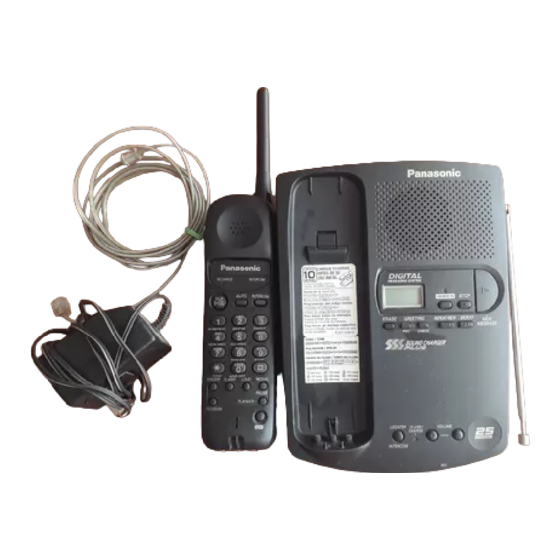
KX-TC1040LAB/KX-TC1040LAW
l
Cordless Answering System
Black Version
White Version
(for Latin America)
© 2001 Kyusyu Matsushita Electronics CO., Ltd. All rights reserved. Unauthorized copying and distribution is a violation of law.
TOP NEXT
http://servis-manual.com/
Advertisement

Related Manuals for Panasonic KX-TC1040LAB

Summary of Contents for Panasonic KX-TC1040LAB
- Page 1 Service Manual TOP NEXT ORDER NO. KM40111725C3 Telephone Equipment KX-TC1040LAB/KX-TC1040LAW Cordless Answering System Black Version White Version (for Latin America) © 2001 Kyusyu Matsushita Electronics CO., Ltd. All rights reserved. Unauthorized copying and distribution is a violation of law. TOP NEXT...
- Page 2 5 ADJUSTMENTS (BASE UNIT) TOP PREVIOUS NEXT If your unit have below symptoms, adjust each item using remedy column from the table. Symptom Remedy The base unit dose not respond to a call from handset. Make adjustments in item (A) The base unit dose not transmit or the transmit frequency is off.
-
Page 3: Circuit Board (Base Unit)
The connection of adjustment equipments are as shown in CIRCUIT BOARD (BASE UNIT) TOP PREVIOUS NEXT http://servis-manual.com/... - Page 4 6 ADJUSTMENTS (HANDSET) TOP PREVIOUS NEXT If your unit have below symptoms, adjust each item using remedy column from the table. Symptom Remedy The movement of Battery Low Indicator is wrong. Make confirmation in item (A) The base unit does not respond to a call from handset. Make adjustment in item (B) The base unit does not transmit or the transmit frequency is off.
-
Page 5: Circuit Board (Handset)
The connections of adjustment equipments are as shown CIRCUIT BOARD (HANDSET) 6.1 Test Mode Flow Chart for Maintenance of the BASE UNIT TOP PREVIOUS NEXT http://servis-manual.com/... - Page 6 6.1 Test Mode Flow Chart for Maintenance of the BASE UNIT TOP PREVIOUS NEXT TOP PREVIOUS NEXT http://servis-manual.com/...
-
Page 7: Troubleshooting Guide
17 TROUBLESHOOTING GUIDE TOP PREVIOUS NEXT Display Symptom Remedy The initialization was tried, but it could not be done. Confirm Flash Memory is equipped. Confirm the connection of Flash Memory. Confirm the power supply of Flash Memory. When no error is found in above-mentioned items, Flash Memory has a defect. Replace Flash Memory. - Page 8 18 TROUBLESHOOTING GUIDE (BASE UNIT) TOP PREVIOUS NEXT Base Unit Condition: 1. Set the dialing mode selector to "Tone". When checking the base unit only. Check the base unit as shown by following below flow chart. http://servis-manual.com/...
- Page 9 18.1 Troubleshooting Step 1: 18.2 Troubleshooting Step 2: 18.3 Troubleshooting Step 3: TOP PREVIOUS NEXT http://servis-manual.com/...
- Page 10 18.1 Troubleshooting Step 1: TOP PREVIOUS NEXT The base unit does not flash In Use/Charge indicator. TOP PREVIOUS NEXT http://servis-manual.com/...
- Page 11 18.2 Troubleshooting Step 2: TOP PREVIOUS NEXT The charge indicator does not light. TOP PREVIOUS NEXT http://servis-manual.com/...
- Page 12 18.3 Troubleshooting Step 3: TOP PREVIOUS NEXT 1. The INUSE/CHARGE indicator does not flash. 2. The beep is not heard from the handset. TOP PREVIOUS NEXT http://servis-manual.com/...
- Page 13 19 TROUBLESHOOTING GUIDE (HANDSET) TOP PREVIOUS NEXT Use the right base unit for this troubleshooting.Charge the battery of the handset on the base unit. Base unit condition: 1. Connect the AC Adaptor (PQLV1Z) plug into DC IN jack and the another end into a power outlet (AC 120 V, 60Hz).
- Page 14 19.1 Troubleshooting Step 1: TOP PREVIOUS NEXT The handset does not becomes the battery save mode. TOP PREVIOUS NEXT http://servis-manual.com/...
- Page 15 19.2 Troubleshooting Step 2: TOP PREVIOUS NEXT The Beep is not heard on the Handset. TOP PREVIOUS NEXT http://servis-manual.com/...
- Page 16 Stránka č. 1 z 1 19.3 Troubleshooting Step 3: TOP PREVIOUS NEXT The TALK indicator does not flash (Check the data reception). Check Point Check the signal of receiver data circuit RECEIVER DATA CIRCUIT TOP PREVIOUS NEXT file://C:\Documents%20and%20Settings\Admin\Plocha\SCHÉMATA\VIDEA\PANAS... 5. 8. 2004 http://servis-manual.com/...
- Page 17 3.0kHz/devi 1kHz TX SIGNAL RX SIGNAL 3.1kHz/devi 1kHz 300mV (-20dBm) 150mV (-26dBm) 130mV (-27dBm) 350mV (-16dBm) 800mV (-9dBm) IC801 400mV (-15dBm) IC802...
- Page 18 TX SIGNAL RX SIGNAL Int'com TX Int'com RX 4.9V 4.2V IC301 300mV (TX) (RX) 300mV 1kHz 180mV (TX) -25dBm/600 (RX) IC703 4.2V IC702 250mV 4.2V (TX) 4.2V IC701 4.2V 4.2V 4.2V 4.2V...
- Page 19 TX SIGNAL RX SIGNAL Int'com TX Int'com RX IC401 100mV (RX) (Int'com RX) 450mV 450mV (RX) (TX) 1800mV 1kHz 450mV -51dBm/600 3kHz/devv (RX) (RX) 1kHz 800mV 200mV (TX) (Int'com TX) KX-TC1040LAB/LAW : SCHEMATIC DIAGRAM (BASE UNIT) Main...
- Page 20 1.969 1.973 DC 2.596V TALK 2.613V STBY 50Ω AC(AF) AC(RF) AC(AF) SEND AC(AF) IC101 AC(AF) AC(AF) SEND AC(AF) BETWEEN BOTH TERMINALS AC(AF) 2.046 25.53V 2.05 255mV IC301 TX DATA AC(RF) SEND...
- Page 21 2.614 STBY 2.405 2.416 2.482 +2.6V 2.497 IC901 TALK STBY 31 55.4mV 2.413mV 32 2.397mV 2.412mV 33 2.388mV 2.402mV 36 0.283mV 2.394mV 37 2.380mV 2.394mV 41 4.5mV 0.1mV 2.389 2.403 MIC INPUT -40 dBm KX-TC1040LAB/LAW : SCHEMATIC DIAGRAM (HANDSET) Main...