
Related Manuals for Kohler Mira Sport Thermostatic 9.0


Summary of Contents for Kohler Mira Sport Thermostatic 9.0
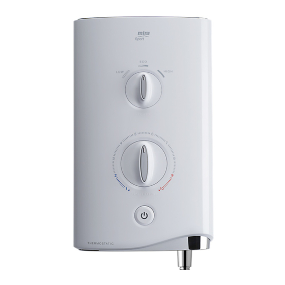
- Page 1 Mira Sport Thermostatic 9.0 and 9.8 kW For SPARES, ADVICE or REPAIRS please call us free on 0800 001 4040 (UK only) Installation and User Guide These instructions must be left with the user 1494247-W2-A...
- Page 2 1494247-W2-A...
-
Page 3: Important Safety Information
Important Safety Information WARNING - This shower can deliver scalding temperatures, cause fire, electric shock or other personal injury if not operated, or maintained in accordance with the instructions, warnings and cautions contained in this guide and on the appliance. Please read the important safety information and the operation section of this guide before using the shower. - Page 4 9. Installation of the shower must be carried out in accordance with these instructions by qualified, competent personnel. Read all instructions before installing the shower. 10. DO NOT switch the shower on if water starts leaking from the shower case. Isolate the electrical supply to the shower immediately. 11.
- Page 5 Only Kohler Mira recommended accessories should be used. 23. DO NOT perform any unspecified modifications, or drill or cut holes in the product other than instructed by this guide.
-
Page 6: Pack Contents
Pack Contents Tick the appropriate boxes to familiarize yourself with the part names and to confirm that the parts are included. 1 x Mira Sport Thermostatic Electric Shower 1 x Olive 1 x Compression Nut 3 x Fixing Screws ... -
Page 7: Products Covered
Products manufactured by Kohler Mira Ltd are designed to be safe provided, that they are installed used and maintained in good working order, in accordance with our instructions and recommendations. -
Page 8: Specifications
Specifications Thermostatic Variant Plumbing Sport 9.0 Sport 9.8 Minimum Dynamic Pressure 70 kPa (0.7 bar) Maximum Dynamic Pressure * 500 kPa (5 bar) Minimum Static Pressure 20 kPa (0.2 bar) Maximum Static Pressure * 1000 kPa (10 bar) Maximum Inlet Temperature 30°C Minimum Inlet Temperature 2°C... -
Page 9: Disposal And Recycling
Guarantee The Mira Sport Thermostatic has been designed for domestic use only, Mira Showers guarantee the Mira Sport Thermostatic against any defect in materials or workmanship for a period of two years from the date of purchase (shower fittings for one year). For non-domestic installations, Mira Showers guarantee the Mira Sport Thermostatic against any defect in materials or workmanship for a period of one year from the date of purchase. -
Page 10: Installation Requirements
Installation Requirements Plumbing 1. The plumbing installation must comply with all national or local water regulations and all relevant building regulations, or any particular regulation or practice specified by the local water supply company. 2. DO NOT use sealing compounds on any pipe fitting or joints. 3. - Page 11 17. A water treatment device should be installed where the water hardness may exceed 200 ppm. Malfunctions caused by excessive limescale formation are not covered by this shower’s guarantee (see back page for details). 18. The installation must not cause the hose to be sharply kinked during normal use.
- Page 12 Electrical 1. The electrical installation must comply with BS 7671 (commonly referred to as the IEE Wiring Regulations) and all relevant building regulations, or any particular regulation or practice specified by the local electricity supply company. 2. Ensure that all circuit protection devices, switches and cabling is adequate for the rated current of the shower and that the rating of the electricity supply company fuse and the consumer unit are adequate for the additional demand.
-
Page 13: Installation
Installation Warning! Turn off the electrical and water supplies before proceeding with the installation of the shower. Remove the three screws that Screws hold the cover on and remove Service the cover. Tunnel Remove the service tunnel. Using the installation template supplied, mark the positions of the three fixing holes. - Page 14 Determine the direction and route of the incoming water supply: falling (entering the shower from the top), or rising (entering the shower from the bottom). Note: DO NOT use an incoming supply entering the shower directly from the back. Add an elbow to the supply pipe and connect it as a rising or falling supply.
- Page 15 Connect the inlet supply pipe to the inlet connector using Inlet the compression nut and olive Connector (supplied). Always provide mechanical support when making plumbing connections. Upon Olive completion of the installation ensure connections and back Compression case are not under any stress due to misaligned pipework or Inlet Supply electrical cables.
- Page 16 Screws E n s u r e t h e e a r t h b o n d i n g c o m p l i e s w i t h r e l e v a n t regulations.
- Page 17 Commissioning HIGH POWER TEMPERATURE TEMPERATURE Turn temperature control to Turn power control to low. Switch on the electrical supply. the cold position. HIGH COLD 0 - 15 secs Water flows freely within a POWER POWER Push START/STOP button. Turn power control to Eco. few seconds, temperature Light in the button illuminates.
-
Page 18: Operation
Operation Read the section “Important Safety Information” first. Push the START/STOP button to turn ON the appliance. Light in the button illuminates. Switch on the electrical supply. HIGH POWER POWER Turn the power control to the desired TEMPERATURE TEMPERATURE position. Adjust the temperature as required. - Page 19 A small amount of water may continue to drain over a few minutes. Warning! Turning the shower off and back on during showering may result in unstable temperatures at the showerhead. Always ensure the temperature has stabilised before re-using the shower. Note: A slight hissing sound may be heard from the shower during operation.
-
Page 20: Fault Diagnosis
Fault Diagnosis In the event of a malfunction of the shower, the troubleshooting information below provides details on possible causes and remedies that may be carried out by qualified, competent personnel. Warning! There are no user serviceable components beneath the cover of the shower. - Page 21 Start/Stop Power Symptom Light is Control Possible Cause Possible Remedy ON or OFF Position Showerhead Insufficient water supply Minimum static pressure dripping. pressure for shut off. to ensure shut off and prevent dripping is 20 kPa (0.2 bar). Note: If other appliances are operating, static pressure may drop below 20 kPa (0.2 bar).
- Page 22 Start/Stop Power Symptom Light is Control Possible Cause Possible Remedy ON or OFF Position Microswitch failure. Replace microswitch. change in Insufficient mains water Contact local water temperature pressure. company. between Low / Eco / Possible failure of flow Use a suitable device to High setting.
-
Page 23: User Maintenance
User Maintenance In the event of a malfunction of the shower, a fault finding table is provided in this guide detailing possible causes and remedies that may be carried out by non- qualified personnel. WARNING! TO REDUCE THE RISK OF FIRE, ELECTRIC SHOCK, INJURY OR PRODUCT DAMAGE: •... - Page 24 Servicing Warning! There are no user serviceable parts inside the shower. Servicing of the shower must only be carried out by qualified, competent personnel following the instructions provided in this guide and those provided with any spare part. Before replacing any parts, ensure that the underlying cause of the malfunction has been resolved.
-
Page 25: Spare Parts
Spare Parts 1563.719 Thermal Switch 1746.449 Terminal Block 1746.458 (9.0kW) 1746.459 (9.8kW) Heater Tank 1746.444 (includes microswitches) Switch 1563.536 Assembly Control Belt 1563.540 1829.062 Inlet Valve Inlet Filter 1563.538 1829.063 Temp Cam Inlet & Pulley Connector 416.38 Inlet Clamp 416.51 Coil 1746.461 1746.446... - Page 26 Notes 1494247-W2-A...
- Page 27 Notes 1494247-W2-A...
-
Page 28: Customer Support
Kohler Mira Limited. Cromwell Road, K/E S.A.S. Cheltenham, 3 rue de Brennus, The company reserves the right Gloucestershire 93631, La Plaine Saint-Denis, to alter product specifi cations GL52 5EP France without notice. 14648 © Kohler Mira Limited, September 2021 1473739-W6-A 1494247-W2-A...