Table of Contents
Advertisement
Advertisement
Table of Contents

Related Manuals for Furuno ETR-10N


Summary of Contents for Furuno ETR-10N
- Page 1 NETWORK SOUNDER ETR-6/10N...
- Page 2 9 - 5 2 , A s h i h a r a - c h o , N i s h i n o m i y a , J a p a n Te l e p h o n e : 0 7 9 8 - 6 5 - 2 1 1 1 Te l e f a x : 0 7 9 8 - 6 5 - 4 2 0 0...
- Page 3 The installer of the equipment is solely responsible for the proper installation of the equipment. FURUNO will assume no responsibility for any damage associated with improper installation. Be sure that the power supply is compatible with the voltage rating of the equipment.
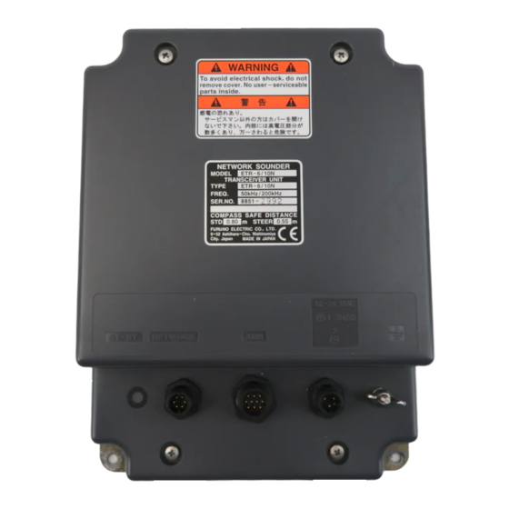
- Page 4 A warning label is attached to the equip- ment. Do not remove the label. If the label is missing or illegible, contact a FURUNO agent or dealer. To avoid electrical shock, do not remove cover. No user-serviceable parts inside.
-
Page 5: Table Of Contents
SAFETY INSTRUCTIONS... i SYSTEM CONFIGURATION... iv EQUIPMENT LISTS ... v 1. MOUNTING ... 1 1.1 Network Sounder... 1 1.2 Thru-hull Mount Transducer 520-5PSD, 520-5MSD ... 2 1.3 Transom Mount Transducer 520-5PWD, Optional Transom Mount Triducer 520ST-PWD... 5 1.4 Inside-hull Mount Transducer 520-5PSD, 520-5MSD ... 7 1.5 Optional Water Temperature/Speed Sensors ... -
Page 6: System Configuration
PR-62 12-24 VDC 100/110/220/230 VAC, 1 , 50/60 Hz *: HUB may be connected to 3 sets of NAVnet radar or plotter. : Standard : Option : External Equipment Network Sounder ETR-6/10N Transducer Water temperature/ 520-5PSD speed sensor 520-5PWD ST-02MSB... -
Page 7: Equipment Lists
EQUIPMENT LISTS Standard supply Name Type Network Sounder ETR-6/10N Spare Parts SP02-04301 Installation CP02-06800 Materials CP02-06810 Code No. Remarks 1 set 000-027-897 MJ-A3SPF0013-035 (3 A) MJ-A6SPF0014-050 (5 m) 1 set +Tapping screw 000-027-898 MJ-A3SPF0013-035 (3 A) +Tapping screw... - Page 8 Optional supply No. Name Type Distribution MB-1000 Cable Assy. 02S4089 MJ-A6SPF0014-010 MJ-A6SPF0014-050 MJ-A6SPF0014-100 MJ-A6SPF0014-200 MJ-A6SPF0014-300 MJ-A6SRMD/TM11AP8-005 000-144-463 Inside Hull 22S0191 Kit S Triducer 524ST-MSD 520ST-PWD 525ST-MSD 525ST-PWD Transducer 520-5PSD 520-5PWD 520-5MSD 50B-6 50B-6B 50B-6G 50B-9B 50B-62M 50B-92M 200B-5 200B-5S 50/200-1T 50/200-12M ST Sensor ST-02MSB...
-
Page 9: Mounting
1. MOUNTING 1.1 Network Sounder Mounting considerations The network sounder can be installed on the deck or on the bulkhead. When selecting a mounting location for the network sounder, keep the following in mind: • The temperature and humidity should be moderate and stable. -
Page 10: Thru-Hull Mount Transducer 520-5Psd, 520-5Msd
1.2 Thru-hull Mount Transducer 520-5PSD, 520-5MSD Transducer mounting location This type of mounting provides the best performance of all, since the transducer protrudes from the hull and the effect of air bubbles and turbulence near the hull skin is reduced. When the boat has a keel, the transducer should be at least 30 cm away from it. - Page 11 Acceptable transducer mounting locations Deep-V hull * Position 1/2 to 1/3 length of the hull from stern. * 15 to 30 cm from center line (inside first lifting strakes). Figure 1-3 Transducer mounting location on deep-V hull High speed V-planing hull Figure 1-4 Transducer mounting location on high speed V-planing hull Typical thru-hull mount transducer installations Fairing block...
- Page 12 Procedure for installing the thru-hull mount transducer 1. With the boat hauled out of the water, mark the location selected for mounting the transducer on the bottom of the hull. 2. If the hull is not level within 15 in any direction, fairing blocks made out of teak should be used between the transducer and hull, both inside and outside, to keep the transducer face parallel with the water line.
-
Page 13: Transom Mount Transducer 520-5Pwd, Optional Transom Mount Triducer 520St-Pwd
1.3 Transom Mount Transducer 520-5PWD, Optional Transom Mount Triducer 520ST-PWD This type of mounting is very commonly employed for outboard motor boats. Do not use this method on an inboard motor boat because turbulence is created by the propeller ahead of the transducer. - Page 14 M5x20 Tape Figure 1-8 Transom mount transducer, mounting flush with hull Installing the transom mount transducer projecting from hull (for deep-V hulls) This method is employed on deep-V hulls and provides good performance because the effects of air bubbles are minimal. Install the transducer parallel with water surface; not flush with hull.
-
Page 15: Inside-Hull Mount Transducer 520-5Psd, 520-5Msd
1.4 Inside-hull Mount Transducer 520-5PSD, 520-5MSD Necessary tools You will need the following tools: • Sandpaper (#100) • Silicone sealant • Silicone grease Remarks on installation • Turn off the engine and anchor the boat while installing the equipment. • Install the transducer in the engine room. - Page 16 Attaching the inside-hull mount transducer 1. Clean the transducer face to remove any foreign material. Lightly roughen the transducer face with #100 sandpaper. Also, roughen the inside of the hull where the transducer is to be mounted. 2. Warm the silicone sealant to 40°C before usage to soften it. Coat the transducer face and mounting location with silicone sealant.
-
Page 17: Optional Water Temperature/Speed Sensors
1.5 Optional Water Temperature/Speed Sensors Through-hull mount water temperature/speed sensor ST-02MSB, ST-02PSB Select a suitable mounting location considering the following: • Select a mid-boat flat position. The sensor does not have to be installed perfectly perpendicular. The sensor must not be damaged in dry-docking operation. •... -
Page 18: Optional Water Temperature Sensors
1.6 Optional Water Temperature Sensors Transom mount water temperature sensor T-02MTB • Fix the cable at a convenient location with cable clamp. • When the cable is led in through the transom board, make a hole of approx. 17 mm in diameter to pass the connector. - Page 19 Thru-hull mount water temperature sensor T-02MSB, T-03MSB Select a suitable mounting location considering the following points: • Select a mid-boat flat position. The sensor does not have to be installed perfectly perpendicular. However, the location should not be such that the transducer may be damaged when the boat is dry-docked.
-
Page 20: Optional Triducer 524St-Msd
1.7 Optional Triducer 524ST-MSD The triducer is designed for thru-hull mounting. Mounting considerations When selecting a mounting location keep the following points in mind: • Air bubbles and turbulence caused by movement of the boat seriously degrade the sounding capability of the transducer. The transducer should, therefore, be located in a position where water flow is the smoothest. -
Page 21: Wiring
2. WIRING 2.1 Wiring All wiring is terminated at the network sounder. NAVnet equipment or HUB Transducer Power cable Connect the power cable to the power connector. Connect the leads to the battery (12-24 VDC); white to plus (+) terminal and black to minus (-) terminal. - Page 22 20 cm by 30 cm on the outside of the hull bottom to provide a ground point. Note: Use a "closed" lug to make the ground connection at the network sounder. Do not use an "open-type" lug (...
-
Page 23: Optional Sensors
2.2 Optional Sensors Water temperature sensor Connect the water temperature sensor (option) or water temperature/speed sensor (option) to the XDR port with the converter connector (Type: 02S4147, Code No.: 000-141-082, option). MJ-A6SRMD SHIELD TEMP TEMP0V Temperature sensor MJ-A10SRMD Transducer XDR+ XDR SHIELD XDR- Figure 2-3 Connection of water temperature speed sensor... - Page 24 Water temp., water temp/speed sensor connector Figure 2-5 Connection of transducer, water temperature sensor, Connect to XDR port at network sounder MJ-A10SPF MJ-A6SRMD Tape connector with self-vulcanizing tape and then vinyl tape to waterproof connector. Bind tape end with cable tie.
-
Page 25: Optional 50 Khz And 200 Khz Transducers
200B-5, 200B-5S, 50/200-1T or 50/200-12M, the optional Distribution Box (MB-1000, code no. 000-040-809) is required. Additionally, a cable assembly (02S4089, code no. 000-133-622) is required to connect to the network sounder. Fasten the cable from the Distribution Box to the XDR connector on the network sounder. -
Page 26: Initial Settings
3. INITIAL SETTINGS 3.1 Selecting the Transmission Power The default transmission power is 600 W. If you install the 1 kW transducer, change the jumper connector to #3-4 from #1-2 on J12 as follows:. 1. Detach the power cable from the connector. 2. -
Page 27: Replacing The Fuse
If the fuse blows find out the cause before replacing it. If the fuse blows again after replacement, contact a FURUNO agent or dealer for advice. If the LED lamp on the front panel does not light, the 4 A fuse inside the network sounder may have blown. -
Page 28: Specifications
SPECIFICATIONS OF THE NETWORK SOUNDER 1. GENERAL 1.1. Output Power 600 W/ 1 kW rms nominal, 1 kW requires optional MB-1000 1.2. TX Frequency 50 kHz or 200 kHz, 50/200 kHz exchangeable 1.3. Amplifier type Log amplifier 1.4. Network protocol Ethernet 10BASE-T 1.5.