Advertisement
Available languages
Available languages
Quick Links
Advertisement

Related Manuals for Kavan MIRAI V


Summary of Contents for Kavan MIRAI V
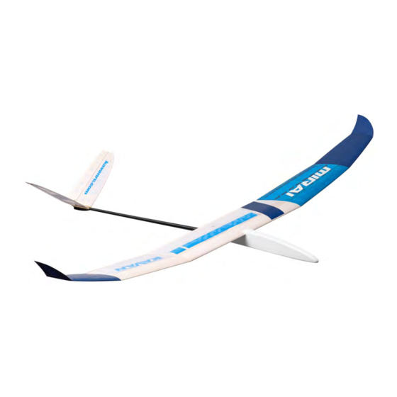
- Page 1 MIRAI V Instruction Manual/Návod ke stavbě/Bauanleitung F3RES/F5RES High Performance Thermal Glider / Electric Glider Vysokovýkonný termický větroň/motorový větroň F3RES/F5RES Der leistungsstarke Thermik-Segler / Motorsegler F3RES/F5RES Rev. 1: 11/2021...
- Page 2 PRECAUTIONS: This R/C model is not a toy. Use it with care and stricktly following the instructions in this manual. Assemble this model following stricktly these instructions. DO NOT modify or alter the model. Failure to do so, the warranty will lapse automatically. Follow the instructions in order to obtain a safe and solid model at the end of the assembly.
-
Page 3: Specification
Unless stated otherwise, use medium cyanoacrylate (CA) glue (KAV9952 joints). The highly loaded parts (wing roots, wing main spars, firewall etc.) KAVAN CA Medium). D-box sheeting and wing ribs are better to be glued should be glued together using 30 minute (or slower) epoxy (like KAV9967... - Page 4 (Fig. 2) tor and use the spinner as a jig to align the E1 plywood ring; once satis- ◊ Put the tail surfaces aside for now; they will be finished after the tailplane fied, epoxy it in place. Sand the nose to the desired shape matching your seats are installed to the tail boom.
-
Page 5: Hinging The Control Surfaces
sion bar onto W3/W4 and W7 ribs. Insert the 3 mm carbon torsion bar Hinging the Control Surfaces W37 into the bushings. Do not forget to slide the W36 control horn in ◊ Use strips of a high quality hinging tape (available in hobby shops) or stri- the centre. - Page 6 position. One at a time, set the W22 and W23 airbrakes in the fully exten- Power System Installation (Electric Version) ded position (-24 mm), push the corresponding lever W35 to the airbrake ◊ Fit your motor using appropriate screws to the firewall; secure the ESC and secure with a small drop of cyano to the W37 torsion bar.
-
Page 7: Parts List
Parts List Parts list Building Plan No. Material Building Plan 1:1 Instruction Manual Sheet of Stickers Pushrod Set plastic tube+0.8 mm piano wire Tail Boom carbon tube Ø18x10 mm Pushrod Holder + Formers balsa 1.5 mm + 0.8 mm plywood Bag No. - Page 8 Bag No. 4 – V-tail Stabilizer V1L/R balsa 3 mm Ruddervator balsa 3 mm Stabilizer Tip balsa 3 mm Stabilizer Ribs 2+2+2 V5, V6, V7 balsa 3 mm Carbon Stabilizer Reinforcement carbon 0.5x3 mm Plastic Tube plastic tube Ø3 mm Stabilizer Root Rib V4L/R plywood 1,2 mm...
- Page 9 Pokud není výslovně uvedeno jinak, díly lepte středním vteřinovým lepidlem např. KAV9960 KAVAN Disperzní lepidlo. Pevnostní spoje (kořenové části kříd- (např. KAV9952 KAVAN CA střední). Tuhý potah torzní skříně křídla a žebra la, nosníky atd.) lepte 30minutovým epoxidovým lepidlem, které má vysokou je vhodné...
- Page 10 STAVBA MODELU Ocasní plochy podélná drážka pro ostruhu V12) – viz Det. D. (Obr. 2). Vše je navrženo pro dosažení co nejmenší hmotnosti při dostatečné pevnosti. Trup (verze elektro) Ocasní plochy jsou odnímatelné. ◊ Stavba trupu verze elektro je obdobná stavbě trupu pro větroň s vyjímkou ◊...
- Page 11 ◊ Žebra zasuňte i do drážek v odtokové hraně W17. Tím máte zaručenou středu křídla. ◊ Na zarovnaný konec ucha přilepte balsové žebro přechodu wingletu P17 a správnou rozteč žeber. ◊ Nasuňte pomocný zadní nosník W27, slícujte náběžnou lištu W30 a odto- zabruste na požadovaný...
- Page 13 15 16...
- Page 16 Note: Please note the pictures are just for illustration only– some show our prototype that might differ slightly from the actual, regular series production kits. Pozn.: Mějte, prosím, na paměti, že obrázky jsou pouze ilustrační – některé z nich ukazují náš prototyp, který...
- Page 17 LÉTÁNÍ Ujistěte, že máte akumulátory plně nabité. Nyní (a před každým dalším le- tem) kontrolujte správné fungování celého letového RC vybavení, motoru a pohyby ovládacích ploch. Ujistěte se, že žádná část vybavení se nemůže během letu samovolně pohybovat. Důrazně doporučujeme provést test dosahu RC soupravy v souladu s pokyny výrobce.
- Page 18 Seznam dílů stavebnice Seznam dílů stavebnice Číslo dílu na výkresu Materiál Stavební plán modelu 1:1 Návod ke stavbě Aršík samolepek Lanovod Plastová trubice+drát ocel 0,8 mm Uhlíkový ocasní nosník (Ø18 x 10 mm) Držák lanovodů s přepážkami balsa 1,5 mm + překližka 0,8 mm Sáček č.
- Page 19 Sáček č. 4 - Ocasní plochy V Stabilizátor V1L/R balsa 3 mm Kormidlo balsa 3 mm Koncový oblouk stabilizátoru balsa 3 mm Žebra stabilizátoru 2+2+2 V5, V6, V7 balsa 3 mm Uhlíková výztuha stabilizátoru uhlík 0,5x3 mm Pouzdro vodící tyčky plastová...
- Page 20 Made in the Czech Republic/Vyrobeno v České republice/Hergestellt in der Tschechischen Republik www.kavanrc.com info@kavanrc.com DE, CZ: +49 8374 259 2696 EN, CZ: +420 463 358 712...