Table of Contents
Advertisement
Advertisement
Table of Contents

Related Manuals for Cisco ISB7105W


Summary of Contents for Cisco ISB7105W
- Page 1 Installation Manual Cisco IPTV Receivers Model ISB7105 ISB7105W...
-
Page 2: Table Of Contents
Contents Notice for Installers ......................4 IMPORTANT SAFETY INSTRUCTIONS................4 Change the Way You Watch TV ..................7 What’s In the Carton? ...................... 7 Safety First ........................7 Identify Your Receiver with the Serial Number ..............7 In This Manual ........................7 Protecting You and the Environment ................ -
Page 3: Notice For Installers
Notice for Installers The servicing instructions in this notice are for use by qualifi ed service personnel only. To reduce the risk of electric shock, do not perform any servicing other than that contained in the operating instructions, unless you are qualifi ed to do so. - Page 4 IMPORTANT SAFETY INSTRUCTIONS, continued Protect from Exposure to Moisture Ground the Product and Foreign Objects WARNING: Avoid electric shock and fire hazard! If this product connects to cable wiring, WARNING: Avoid electric shock and fire be sure the cable system is grounded (earthed). hazard! Do not expose this product to dripping or Grounding provides some protection against splashing liquids, rain, or moisture.
-
Page 5: Change The Way You Watch Tv
IP network and your entertainment system. The manual also outlines certain safeguards and installation information. The safety information contained in this manual was developed and provided solely by the receiver manufacturer, Cisco Systems, Inc. Protecting You and the Environment Cisco addresses the environmental impact of networking products throughout their lifecycle, from product development, manufacturing, and use to service and end-of-life. -
Page 6: Front Panel
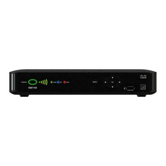
Front Panel MENU POWER LINK ISB7105 4 5 6 1 Power Turns the receiver on or places it in standby. To restart the receiver, press and hold the POWER button for 10 seconds. The LED is green 2 Model Number Identifi es the model number of your receiver as ISB7105 3 Signal Strength Identifi es the strength of the wireless connection... -
Page 7: Back Panel
Back Panel VIDEO AUDIO OPTICAL POWER NETWORK 1 Network Connect to the Ethernet (CAT-5) network at your home, if applicable 2 YPbPr Connect the receiver to the component video input (YPbPr) on the HDTV. See pages 13 and 14 for more information 3 Video Out Connect to composite input on your HDTV or SDTV 4 Audio Out (L/R) -
Page 8: Connecting The Receiver
Connecting the Receiver To connect your receiver to your network and home entertainment devices, complete these steps. Because the connections for a high-defi nition (HD) or standard-defi nition (SD) TV are diff erent, you must determine if your TV is HD or SD. -
Page 9: Isb7105 Wireless Network Connection
ISB7105 Wireless Network Connection POWER LINK The ISB7105 receiver allows for easy and secure ISB7105 connection to IPTV services. The signal strength indicator on the front panel of the receiver identifi es the strength of the wireless connection and aids in Signal Strength Indicator the proper placement of the receiver. -
Page 10: Connecting The Wireless Access Point To The Wireless Gateway
Connecting the Wireless Access Point to the Wireless Gateway 1. Connect the 12 VDC Power Supply plug RJ-45 Wireless Cable Gateway on the access point to the wall power Ethernet Port outlet. Use only the power adapter provided with the product. 12VDC 2. -
Page 11: Connections For A High-Defi Nition Tv (Hdtv)
Connections for a High-Defi nition TV (HDTV) To use the receiver with an HDTV, you must make one of the following connections to view the HD content. Refer to the owner’s manual for your TV and the cabling diagrams in this manual for more detailed connection information. Although all connections provide you with quality service, we list the connections in our recommended order. -
Page 12: Connections For A Standard-Defi Nition Tv (Sdtv)
Connections for a Standard-Defi nition TV (SDTV) When using the receiver with an SDTV, you must make one of the following connections to view content. Some SDTVs may not have all these connections. Refer to the owner’s manual for your TV and the cabling diagrams in this manual for more detailed information. -
Page 13: Connections For A Vcr Or Dvd Recorder
Connections for a VCR or DVD Recorder When using the receiver with a VCR or DVD recorder, you must make one of the following connections to view content. Although all connections provide you with quality service, we list the connections in our recommended order. -
Page 14: Connecting To An Hdtv With An Hdmi Connector
Connecting to an HDTV with an HDMI Connector Cable Used in this Confi guration • 1 HDMI Cable Notes: • The HDMI port on the TV must support high-bandwidth digital content protection (HDCP). ™ • The HDMI interface supports Dolby Digital 5.1 audio. -
Page 15: Connecting To An Hdtv With A Dvi Connector
Connecting to an HDTV with a DVI Connector Cables Used in this Confi guration • 1 HDMI-to-DVI Cable or 1 HDMI Cable and 1 HDMI-to-DVI Adapter • 1 Audio Left/Right Cable (You can also use an optical cable [indicated by the dotted line] instead of the Audio Left/Right Cable as shown in the diagram, dependent upon your TV’s capabilities.) Notes:... -
Page 16: Connecting To An Hdtv With Component (Ypbpr) Connectors
Connecting to an HDTV with Component (YPbPr) Connectors Cables Used in this Confi guration • 1 Component Video Cable (YPbPr) • 1 Audio Left/Right Cable (You can also use an optical cable [indicated by the dotted line] instead of the Audio Left/Right Cable as shown in the diagram, dependent upon your TV’s capabilities.) WARNING: Electric shock hazard! Unplug all electronic devices before connecting or disconnecting any device cables to the receiver. -
Page 17: Connecting To An Sdtv With Component (Ypbpr) Connectors
Connecting to an SDTV with Component (YPbPr) Connectors Cables Used in this Confi guration • 1 Component Video Cable (YPbPr) • 1 Audio Left/Right Cable Note: The receiver must be set to the proper standard-defi nition mode. WARNING: Electric shock hazard! Unplug all electronic devices before connecting or disconnecting any device cables to the receiver. -
Page 18: Connecting To An Sdtv With An Rca-Type Connector
Connecting to an SDTV with an RCA-Type Connector Cables Used in this Confi guration • 1 RCA-type Video Cable • 1 Audio Left/Right Cable WARNING: Electric shock hazard! Unplug all electronic devices before connecting or disconnecting any device cables to the receiver. Receiver VIDEO AUDIO... -
Page 19: Connecting To A Home Theater System With Component (Ypbpr) Connectors
Connecting to a Home Theater System with Component (YPbPr) Connectors Cables Used in this Confi guration • 1 Component Video Cable (YPbPr) • 1 Audio Left/Right Cable (You can also use an optical cable [indicated by the dotted line] instead of the Audio Left/Right Cable as shown in the diagram.) Notes: •... -
Page 20: Connecting To A Stereo Vcr Or Dvd Recorder (Optional)
Connecting to a Stereo VCR or DVD Recorder (optional) The diagram below shows how to connect a recording device to your receiver. Although it is possible to watch TV using a connection through your VCR or DVD recorder to the TV, this connection may not provide the best picture, and HDTV users are restricted to an SD format. -
Page 21: Troubleshooting
Troubleshooting If the receiver does not perform as expected, the following tips may help. If you need further assistance, contact your service provider. No Picture • Verify that the power to your TV is turned on. • Verify that your wireless receiver and wireless access point are powered on. •... -
Page 22: Frequently Asked Questions
Frequently Asked Questions What Is Digital Television? Digital television (DTV) is a huge leap forward in television technology compared to analog television that has been widely available since the 1940s. DTV is delivered and displayed using digital encoding, similar to the way a PC operates. By using digital technology, there is no variation in picture and sound quality from the origination point until it is displayed on your television. -
Page 23: Picture Formats
Picture Formats What Is the Diff erence Between a Standard-Screen and a Wide-Screen HDTV? The type of screen your HDTV has (wide-screen or standard-screen) determines how the receiver displays programs on the screen. The picture format for an HDTV is a combination of aspect ratio and screen resolution and is diff erent for standard-screen and wide-screen HDTVs. -
Page 24: Index
Index AC Power input DC Power output Arrow keys Diagrams. See Connecting the receiver to other devices Aspect ratio Digital Video Recorder. See DVR Audio Out 9, 13, 14, 15 Digital TV, What is it DVD Connection 9, 10, 15, 22 Back panel DVI connector 13, 17... - Page 25 Index, continued Keys. See Front panel To TV (Video Out) connector 9, 14, 20 Troubleshooting Network 9, 10, 11 digital, what is it formats Optical Audio Output 9, 13, 17, 18, 21 HDTV, what is it Over-the-air converter box programming resolution screen size.
-
Page 26: Compliance Information
Any changes or modifications not expressly may be required to obtain a separate use license approved by Cisco Systems, Inc., could void the from MPEG LA prior to any use of AVC/H.264 user’s authority to operate the equipment. - Page 27 Federal Communication Commission Interference Statement This equipment has been tested and found to comply with the limits for a Class B digital device, pursuant to Part 15 of the FCC Rules. These limits are designed to provide reasonable protection against harmful interference in a residential installation. This equipment generates, uses and can radiate radio frequency energy and, if not installed and used in accordance with the instructions, may cause harmful interference to radio communications.
- Page 28 IMPORTANT NOTE: Canada RF Exposure Statement: This system has been evaluated for radiofrequency exposure for humans in reference to Canada Health Code 6 (2009) limits. The evaluation was based on evaluation per RSS-102 Rev 4. The minimum separation distance from the antenna to general bystander is 7.9 inches (20cm) to maintain compliance.
- Page 29 Lawrenceville, GA 30042 www.cisco.com Cisco and the Cisco logo are trademarks or registered trademarks of Cisco and/or its affi liates in the U.S. and other countries. To view a list of Cisco trademarks, go to this URL: www.cisco.com/go/trademarks. Manufactured under license from Dolby Laboratories. Dolby is a trademark of Dolby Laboratories.