Table of Contents
Advertisement
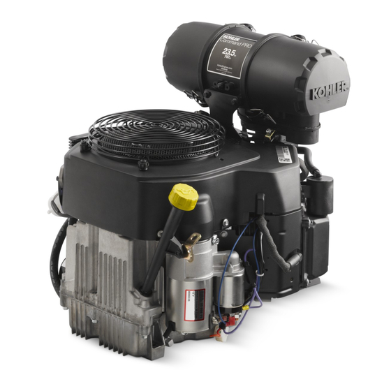
CV682, CV732, CV742, CV752
Service Manual
IMPORTANT:
Read all safety precautions and instructions carefully before operating equipment. Refer to operating
instruction of equipment that this engine powers.
Ensure engine is stopped and level before performing any maintenance or service.
2
Safety
3
Maintenance
5
Specifications
13
Tools and Aids
16
Troubleshooting
20
Air Cleaner/Intake
21
Fuel System
27
Governor System
28
Lubrication System
30
Electrical System
37
Starter System
41
Disassembly/Inspection and Service
54
Reassembly
24 690 37 Rev. B
KohlerEngines.com
1
Advertisement
Table of Contents
Troubleshooting

Related Manuals for Kohler Command PRO CV732


Summary of Contents for Kohler Command PRO CV732
- Page 1 CV682, CV732, CV742, CV752 Service Manual IMPORTANT: Read all safety precautions and instructions carefully before operating equipment. Refer to operating instruction of equipment that this engine powers. Ensure engine is stopped and level before performing any maintenance or service. Safety Maintenance Specifications Tools and Aids...
-
Page 2: Safety Precautions
Safety SAFETY PRECAUTIONS WARNING: A hazard that could result in death, serious injury, or substantial property damage. CAUTION: A hazard that could result in minor personal injury or property damage. NOTE: is used to notify people of important installation, operation, or maintenance information. CAUTION WARNING WARNING... -
Page 3: Maintenance Instructions
Have a Kohler authorized dealer perform this service. REPAIRS/SERVICE PARTS Kohler genuine service parts can be purchased from Kohler authorized dealers. To find a local Kohler authorized dealer visit KohlerEngines.com or call 1-800-544-2444 (U.S. and Canada). 24 690 37 Rev. B... -
Page 4: Oil Recommendations
Maintenance OIL RECOMMENDATIONS STORAGE We recommend use of Kohler oils for best performance. If engine will be out of service for 2 months or more Other high-quality detergent oils (including synthetic) follow procedure below. of API (American Petroleum Institute) service class SJ 1. -
Page 5: Specifications
Specifications Engine Dimensions Dimensions in millimeters. 413.28 353.69 [16.271] [13.925] Inch equivalents shown in [ ]. PRIMARY AIR FILTER ELEMENT REMOVAL 296.44 241.37 [11.691] [9.503] VALVE COVER SAFETY AIR FILTER 93.05 272.44 135.00 ELEMENT REMOVAL [3.664] [10.726] [5.315] 130.00 AIR FILTER [5.118] AIR FILTER COVER RAIN CAP... -
Page 6: Engine Identification Numbers
Exceeding maximum angle of operation may cause engine damage from insufficient lubrication. Lubricate threads with engine oil prior to assembly. Any and all horsepower (hp) references by Kohler are Certified Power Ratings and per SAE J1940 & J1995 hp standards. Details on Certified Power Ratings can be found at KohlerEngines.com. - Page 7 Specifications TORQUE SPECIFICATIONS CV682 CV732 CV742 CV752 Cylinder Head Fastener (torque in 2 increments) first to 16.9 N·m (150 in. lb.) finally to 35.5 N·m (315 in. lb.) Bolt (torque in 2 increments) first to 22.6 N·m (200 in. lb.) finally to 41.8 N·m (370 in.
-
Page 8: Clearance Specifications
Specifications TORQUE SPECIFICATIONS CV682 CV732 CV742 CV752 Stator Mounting Screw 6.2 N·m (55 in. lb.) Valve Cover Yellow O-Ring Style Cover Fastener w/Integral Metal Spacers 6.2 N·m (55 in. lb.) CLEARANCE SPECIFICATIONS CV682 CV732 CV742 CV752 Camshaft End Play 0.076/0.127 mm (0.0030/0.0050 in.) Running Clearance 0.025/0.063 mm (0.0010/0.0025 in.) Bore I.D. - Page 9 Specifications CLEARANCE SPECIFICATIONS CV682 CV732 CV742 CV752 Crankshaft (continued) Oil Pan End Main Bearing Journal O.D. - New 40.913/40.935 mm (1.6107/1.6116 in.) O.D. - Max. Wear Limit 40.84 mm (1.608 in.) Max. Taper 0.022 mm (0.0009 in.) Max. Out-of-Round 0.025 mm (0.0010 in.) Connecting Rod Journal O.D.
- Page 10 Specifications CLEARANCE SPECIFICATIONS CV682 CV732 CV742 CV752 Piston, Piston Rings, and Piston Pin Piston-to-Piston Pin Running Clearance 0.006/0.017 mm (0.0002/0.0007 in.) Pin Bore I.D. 17.006/17.012 mm (0.6695/0.6698 in.) Max. Wear Limit 17.025 mm (0.6703 in.) Pin O.D. 16.995/17.000 mm (0.6691/0.6693 in.) Max.
- Page 11 Specifications CLEARANCE SPECIFICATIONS CV682 CV732 CV742 CV752 Valves and Valve Lifters Hydraulic Valve Lifter to Crankcase Running Clearance 0.0241/0.0501 mm (0.0009/0.0020 in.) Intake Valve Stem-to-Valve Guide Running Clearance 0.038/0.076 mm (0.0015/0.0030 in.) Exhaust Valve Stem-to-Valve Guide Running Clearance 0.050/0.088 mm (0.0020/0.0035 in.) Intake Valve Guide I.D.
-
Page 12: General Torque Values
Specifications GENERAL TORQUE VALUES English Fastener Torque Recommendations for Standard Applications Bolts, Screws, Nuts and Fasteners Assembled Into Cast Iron or Steel Grade 2 or 5 Fasteners Into Aluminum Size Grade 2 Grade 5 Grade 8 Tightening Torque: N·m (in. lb.) ± 20% 8-32 2.3 (20) 2.8 (25) -
Page 13: Tools And Aids
Here is a list of tools and their source. SEPARATE TOOL SUPPLIERS Kohler Tools SE Tools Design Technology Inc. Contact your local Kohler source of 415 Howard St. 768 Burr Oak Drive supply. Lapeer, MI 48446 Westmont, IL 60559... - Page 14 For reaming worn valve guides to accept replacement oversize valves. Can be used in low-speed drill press or with handle below for hand reaming. Reamer Handle Design Technology Inc. For hand reaming using Kohler 25 455 12-S reamer. DTI-K830 AIDS Description Source/Part No.
- Page 15 Tools and Aids FLYWHEEL HOLDING TOOL ROCKER ARM/CRANKSHAFT TOOL A flywheel holding tool can be made out of an old junk A spanner wrench to lift rocker arms or turn crankshaft flywheel ring gear and used in place of a strap wrench. may be made out of an old junk connecting rod.
-
Page 16: Troubleshooting Guide
Troubleshooting TROUBLESHOOTING GUIDE When troubles occur, be sure to check simple causes which, at first, may seem too obvious to be considered. For example, a starting problem could be caused by an empty fuel tank. Some general common causes of engine troubles are listed below and vary by engine specification. Use these to locate causing factors. - Page 17 Troubleshooting EXTERNAL ENGINE INSPECTION Engine Loses Power NOTE: It is good practice to drain oil at a location away ● Dirty air cleaner element. from workbench. Be sure to allow ample time for ● Engine overheated. complete drainage. ● Excessive engine load. ●...
-
Page 18: Crankcase Vacuum Test
Troubleshooting CRANKCASE VACUUM TEST WARNING WARNING Carbon Monoxide can cause severe nausea, Rotating Parts can cause severe injury. fainting or death. Stay away while engine is in operation. Avoid inhaling exhaust fumes. Engine exhaust gases contain poisonous carbon Keep hands, feet, hair, and clothing away from all monoxide. -
Page 19: Compression Test
Troubleshooting COMPRESSION TEST For Command Twins: A compression test is best performed on a warm engine. Clean any dirt or debris away from base of spark plug(s) before removing them. Be sure choke is off, and throttle is wide open during test. Compression should be at least 160 psi and should not vary more than 15% between cylinders. -
Page 20: Air Cleaner/Intake
Air Cleaner/Intake AIR CLEANER 1. Unhook retaining clips and remove end cap(s). These systems are CARB/EPA certified and components 2. Check and clean inlet screen (if equipped). should not be altered or modified in any way. 3. Pull air cleaner element out of housing and replace. Air Cleaner Components Check condition of inner element;... -
Page 21: Fuel Pump
3. Connect pulse line to new fuel pump and make sure Low permeation fuel line must be installed on carbureted opposite end is properly connected to fitting on Kohler Co. engines to maintain EPA and CARB crankcase. regulatory compliance. 4. Attach new fuel pump using screws. Torque screws FUEL PUMP to 2.3 N·m (20 in. - Page 22 Fuel System CARBURETOR Gasoline is extremely flammable and its vapors can WARNING explode if ignited. Store gasoline only in approved Explosive Fuel can cause fires and severe containers, in well ventilated, unoccupied buildings, away burns. from sparks or flames. Spilled fuel could ignite if it comes in contact with hot parts or sparks from ignition.
-
Page 23: Troubleshooting Checklist
Fuel System Engines in this series are equipped with a two-barrel side-draft carburetor with fixed main jets on a matching intake manifold. Carburetor features a self-relieving choke, serviceable slow jets, main jets, accelerator pump, and a fuel shutdown solenoid. 4. Make sure air cleaner base and carburetor are Troubleshooting Checklist securely fastened to engine using gaskets in good When engine starts hard, runs roughly or stalls at low... - Page 24 Fuel System Fuel Shut-Off Solenoid Carburetor Adjustments Carburetors are equipped with a fuel shut-off solenoid. NOTE: Carburetor adjustments should be made only Solenoid is attached to fuel bowl. Solenoid has a spring- after engine has warmed up. loaded pin that retracts when 12 volts is applied to lead, Carburetor is designed to deliver correct fuel-to-air allowing fuel flow to main jet.
- Page 25 Fuel System 1. Perform removal procedures for appropriate air Carburetor Servicing cleaner and carburetor outlined in Disassembly. 2. Clean exterior surfaces of dirt or foreign material WARNING before disassembling carburetor. Disconnect accelerator pump vacuum hose from bottom of bowl. Remove screws and carefully separate fuel bowl Accidental Starts can cause severe injury or from carburetor.
- Page 26 Engines may require a high altitude carburetor kit to ensure correct engine operation at altitudes above 1219 meters (4000 ft.). To obtain high altitude kit information or to find a Kohler authorized dealer visit KohlerEngines.com or call 1-800-544-2444 (U.S. and Canada).
-
Page 27: Governor System
Governor System GOVERNOR Governor works as follows: Engine is equipped with a centrifugal flyweight ● Centrifugal force acting on rotating governor gear mechanical governor. It is designed to hold engine assembly causes flyweights to move outward as speed constant under changing load conditions. speed increases. -
Page 28: Lubrication System
Lubrication System This engine uses a full pressure lubrication system which CHANGE OIL AND FILTER delivers oil under pressure to crankshaft, camshaft, Change oil while engine is warm. connecting rod bearing surfaces, and hydraulic valve 1. Clean area around oil fill cap/dipstick, drain plug/oil lifters. -
Page 29: Installation
Lubrication System OIL SENTRY (if equipped) ™ This switch is designed to prevent engine from starting in a low oil or no oil condition. Oil Sentry may not shut ™ down a running engine before damage occurs. In some applications this switch may activate a warning signal. Read your equipment manuals for more information. -
Page 30: Electrical System
Electrical System SPARK PLUGS Inspection Inspect each spark plug as it is removed from cylinder CAUTION head. Deposits on tip are an indication of general Electrical Shock can cause injury. condition of piston rings, valves, and carburetor. Do not touch wires while engine is running. Normal and fouled plugs are shown in following photos: Normal Spark Plug Component and Details... - Page 31 Electrical System Carbon Fouled ELECTRONIC IGNITION SYSTEMS Ignition System Components Soft, sooty, black deposits indicate incomplete combustion caused by a restricted air cleaner, over rich Kill Switch/ carburetion, weak ignition, or poor compression. Off Position of Air Gap Key Switch Overheated Flywheel Magnet...
- Page 32 Electrical System Wiring Diagram-15/20/25 Amp Regulated Battery Charging System KohlerEngines.com 24 690 37 Rev. B...
- Page 33 Electrical System Ignition Systems These systems use a capacitive discharge (CD) coil. With CDI fixed timing, ignition timing and spark remains constant regardless of engine speed. Timing of spark is controlled by location of flywheel magnet group as referenced to engine TDC.
-
Page 34: Battery Charging System
Electrical System Test for Spark NOTE: If 2 testers are available, testing can be performed simultaneously for both cylinders. However, if only 1 tester is available, 2 individual tests must be performed. Side not being tested must have spark plug lead connected or grounded. - Page 35 Electrical System To test 20/25 amp rectifier-regulators: 1. 20 amp: Connect single lead adapter in between B+ (center) terminal of rectifier-regulator being tested and squared single end of tandem adapter lead. 25 amp: Connect squared single end of tandem lead adapter to B+ (center/red) lead of rectifier-regulator being tested.
- Page 36 Electrical System 15/20/25 Amp Battery Charging Systems NOTE: Always zero ohmmeter on each scale before testing to ensure accurate readings. Voltage tests should be made with engine running at 3600 RPM with no load. Battery must be good and fully charged. When problems occur in keeping battery charged or battery charges at high rate, charging system or battery might be causing problems.
-
Page 37: Starter System
Starter System NOTE: Do not crank engine continuously for more than 10 seconds. Allow a 60 second cool down period between starting attempts. Failure to follow these guidelines can burn out starter motor. NOTE: If engine develops sufficient speed to disengage starter but does not keep running (a false start), engine rotation must be allowed to come to a complete stop before attempting to restart engine. - Page 38 Starter System SOLENOID SHIFT ELECTRIC STARTERS NOTE: Do not soak armature or use solvent when cleaning. Wipe clean using a soft cloth, or use Solenoid Shift Starter Components compressed air. 1. Remove hex nut and disconnect positive (+) brush lead/bracket from solenoid terminal. 2.
-
Page 39: Shift Fork
4 brushes and springs are serviced as a set. Use a new assembly, with supplied protective tube, against Kohler brush and spring kit if replacement is necessary. end of commutator/armature. Mounting screw 1. Perform steps 1-5 in Starter Disassembly. - Page 40 Starter System b. Position brushes back in their slots so they are flush with I.D. of brush holder assembly. Insert brush installation tool (with extension), or use tube described above from a prior brush installation, through brush holder assembly, so holes in metal mounting clips are up/out. c.
-
Page 41: Disassembly/Inspection And Service
Disassembly/Inspection and Service WARNING Before working on engine or equipment, disable engine as Accidental Starts can cause severe injury or follows: 1) Disconnect spark plug lead(s). 2) Disconnect death. negative (–) battery cable from battery. Disconnect and ground spark plug lead(s) before servicing. - Page 42 Disassembly/Inspection and Service 1. Disconnect fuel lines at carburetor and at in-line fuel Drain Oil From Crankcase and Remove Oil Filter filter. 1. Remove oil fill cap/dipstick and 1 oil drain plug. 2. Disconnect pulse (vacuum) line from crankcase. 2. Allow ample time for oil to drain from crankcase and 3.
- Page 43 Disassembly/Inspection and Service Remove Carburetor Remove Oil Sentry ™ 1. Disconnect lead from Oil Sentry switch. ™ WARNING 2. Remove Oil Sentry switch from breather cover. ™ Explosive Fuel can cause fires and severe burns. Remove Inner Baffle and Breather Cover Do not fill fuel tank while engine is hot or 1.
- Page 44 Disassembly/Inspection and Service Cylinder Head Components Valves Cylinder Head Spark Plug Hydraulic Lifter Valve Stem Seal Valve Spring Keeper Valve Spring Valve Spring Rocker Arm Pivot Push Rod Retainer Rocker Arm Screw Valve Cover O-ring Grommet Valve Cover Gasket Remove Cylinder Heads and Hydraulic Lifters NOTE: Cylinder heads are retained using either screws or nuts and washers on studs.
-
Page 45: Exhaust Valve
Disassembly/Inspection and Service Disassemble Cylinder Heads NOTE: These engines use valve stem seals on intake valves. Use a new seal whenever valve is removed or if seal is deteriorated or damaged in any way. Never reuse an old seal. 1. Remove screws, rocker arm pivots and rocker arms from cylinder head. 2. - Page 46 0.050/0.088 mm damage. If lifters need to be replaced, apply a liberal (0.0020/0.0035 in.), determine whether valve stem or coating of Kohler lubricant to base of each new lifter guide is responsible for excessive clearance. before it is installed.
- Page 47 Replace flywheel if it is cracked. Replace flywheel, crankshaft, and key if flywheel key is sheared or keyway is damaged. Inspect ring gear for cracks or damage. Kohler does not provide ring gears as a serviceable part. Replace flywheel if ring gear is damaged.
- Page 48 Disassembly/Inspection and Service Breather/Oil Pan/Oil Reservoir/Piston Components Remove Oil Pan Assembly 1. Remove screws securing oil pan to crankcase. 2. Locate splitting tabs cast into perimeter of oil pan. Insert drive end of a 1/2" breaker bar between splitting tab and crankcase and turn it to loosen seal. Do not pry on sealing surfaces as this can cause leaks.
- Page 49 Disassembly/Inspection and Service 1. Remove regulating pin and governor gear assembly. Remove Camshaft 2. Remove locking tab thrust washer located under Remove camshaft. governor gear assembly. Inspection and Service 3. Carefully inspect governor gear shaft and replace it NOTE: To prevent repeat failures, camshaft and only if it is damaged.
- Page 50 Disassembly/Inspection and Service Detonation damage occurs when a portion of fuel charge Piston and Rings ignites spontaneously from heat and pressure shortly after ignition. This creates 2 flame fronts, which meet Piston and Rings Components and Details and explode to create extreme hammering pressures on a specific area of piston.
-
Page 51: Connecting Rods
Disassembly/Inspection and Service Install New Piston Rings Connecting Rods Offset, stepped-cap connecting rods are used in all Piston Ring Orientation these engines. Inspection and Service Check bearing area (big end) for excessive wear, score marks, running and side clearances (refer to Specifications). - Page 52 Disassembly/Inspection and Service Inspect gear teeth of crankshaft. If teeth are badly worn, Remove Flywheel End Oil Seal chipped, or some are missing, replacement of crankshaft Remove oil seal from crankcase. will be necessary. Inspect crankshaft bearing surfaces for scoring, Crankcase grooving, etc.
- Page 53 Measuring Piston-to-Bore Clearance Piston Detail 23°-33° Crosshatch NOTE: Kohler pistons are custom-machined to exacting tolerances. When oversizing a cylinder, it should be machined exactly 0.25 mm (0.010 in.) or 0.50 mm (0.020 in.) over new diameter (refer to...
-
Page 54: Install Crankshaft
Reassembly Breather/Oil Pan/Oil Reservoir/Piston Components NOTE: Make sure engine is assembled using all specified torque values, tightening sequences, and clearances. Failure to observe specifications could cause severe engine wear or damage. Always use new gaskets. Apply a small amount of oil to threads of critical fasteners before assembly, unless a sealant or Loctite ®... -
Page 55: Install Camshaft
Reassembly Install Connecting Rods with Pistons and Rings Install Camshaft 1. Liberally apply camshaft lubricant to each cam lobe. Piston and Connecting Rod Details Lubricate camshaft bearing surfaces of crankcase and camshaft with engine oil. 2. Position timing mark of crankshaft gear at 12 o’clock position. - Page 56 Reassembly Flywheel/Ignition Components Install Oil Pan Assembly Torque Sequence 1. Be sure sealing surfaces have been cleaned and prepared. Install a new O-ring in oil pan. 2. Check to make sure that there are no nicks or burrs on sealing surfaces of oil pan or crankcase. 3.
-
Page 57: Install Flywheel
Reassembly 4. Route stator leads in crankcase channel, then install NOTE: Before installing flywheel, make sure crankshaft backing plate. Secure with screws. Torque screws to taper and flywheel hub are clean, dry, and 7.3 N·m (65 in. lb.). completely free of any lubricants. Presence of lubricants can cause flywheel to be over Install Flywheel stressed and damaged when screw is torqued to... - Page 58 Reassembly Heads Secured With Screws Install Hydraulic Lifters 1. Check to make sure there are no nicks or burrs on NOTE: Hydraulic lifters should always be installed in sealing surfaces of cylinder head or crankcase. same position as before disassembly. Exhaust 2.
-
Page 59: Install Ignition Modules
Reassembly 5. Insert a 0.25 mm (0.009 in.) flat feeler gauge Install Push Rods and Rocker Arms between magnet and ignition module. Loosen NOTE: Push rods should always be installed in same screws enough to allow magnet to pull module down position as before disassembly. - Page 60 Reassembly External Engine Components Guard Blower Housing Fuel Filter Rectifier-Regulator Outer Baffle Electric Starter Inner Baffle Air Cleaner Air Cleaner Gasket Support Bracket Fuel Pump Oil Cooler O-ring Nipple Oil Filter Plastic Debris Screen Metal Debris Screen Support Ring Spacer KohlerEngines.com 24 690 37 Rev.
- Page 61 Reassembly 3. Position outer baffles and secure using screws (two Install Breather Cover and Inner Baffle long, two short) in front mounting holes (into cylinder Breather Cover Torque Sequence head), including any lifting strap or attached bracket(s). Install two short screws in upper mounting holes of outer baffles (into backing plates).
- Page 62 Reassembly Install Oil Sentry (if equipped) Install Valve Covers ™ 1. Apply pipe sealant with Teflon (Loctite 592™ ® ® ® Torque Sequence Thread Sealant or equivalent) to threads of Oil Sentry switch and install it into breather cover. ™ Torque to 4.5 N·m (40 in.
-
Page 63: Install Carburetor
Reassembly Control Panel Components Throttle Control Control Bracket Lock Nut Flat Washer Lever Throttle Shaft Throttle Control Throttle Shaft Spring Throttle Shaft Bracket Lever Governed Idle Spacer Governor Spring Governed Idle Spring Bracket Governor Lever Linkage Spring Throttle Linkage Air Cleaner Gasket Carburetor Gasket Carburetor Choke Lever... - Page 64 Reassembly Install External Governor Controls Governor Lever and Hole Position/RPM Chart (Governed Idle, 10% Regulation) 1. Install governor lever onto governor cross shaft. Governor 2. Connect choke linkage into bushing/lever from back. High Idle Governor Lever Spring Color Make certain that control shaft offset is back. Hole No.
-
Page 65: Install Muffler
Reassembly 2. Some engines have an evap connector fitting on the Install Fuel Pump air cleaner housing. If this was removed, secure fitting to housing with hi-lo screw. Torque screw to WARNING 2.1 N·m (19 in. lb.). Explosive Fuel can cause fires and severe 3. - Page 66 Reassembly Connect Spark Plug Leads Connect leads to spark plugs. Prepare Engine for Operation Engine is now completely reassembled. Before starting or operating engine, be sure to do following. 1. Make sure all hardware is tightened securely. 2. Make sure oil drain plugs, Oil Sentry pressure ™...
- Page 67 24 690 37 Rev. B KohlerEngines.com...
- Page 68 1P24 690 37 85612 28087 © 2015 by Kohler Co. All rights reserved. KohlerEngines.com 24 690 37 Rev. B...