Table of Contents
Advertisement
Quick Links
www.ti.com
User's Guide
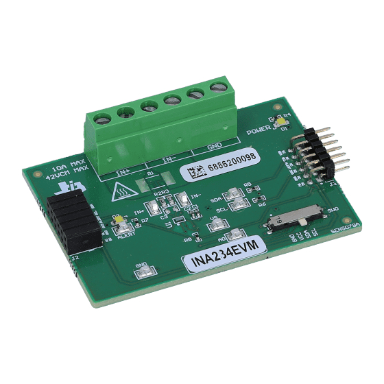
INA234EVM and INA236EVM
This user's guide describes the characteristics, operation, and use of the INA234 and INA236 evaluation
modules (EVMs). These EVMs are designed to evaluate the performance of the INA234 and INA236.
Throughout this document, the terms evaluation board, evaluation module, and EVM are synonymous with
the INA234EVM and INA236EVM. This document includes a schematic, reference printed circuit board (PCB)
layouts, and a complete bill of materials (BOM).
SBOU264 – MAY 2021
Submit Document Feedback
ABSTRACT
Copyright © 2021 Texas Instruments Incorporated
INA234EVM and INA236EVM
1
Advertisement
Table of Contents

Related Manuals for Texas Instruments INA234EVM


Summary of Contents for Texas Instruments INA234EVM
- Page 1 (EVMs). These EVMs are designed to evaluate the performance of the INA234 and INA236. Throughout this document, the terms evaluation board, evaluation module, and EVM are synonymous with the INA234EVM and INA236EVM. This document includes a schematic, reference printed circuit board (PCB) layouts, and a complete bill of materials (BOM).
-
Page 2: Table Of Contents
Table of Contents www.ti.com Table of Contents Trademarks....................................2 Overview....................................3 2.1 Kit Contents..................................3 2.2 Related Documentation From Texas Instruments......................3 Hardware....................................3.1 Features..................................... Operation....................................5 4.1 Quick Start Setup................................4.2 EVM Operation...................................5 5 Circuitry....................................5.1 Current Sensing IC................................15 5.2 Input Signal Path................................15 5.3 Digital Circuitry................................. -
Page 3: Overview
Texas Instruments Product Information Center any component is missing. Table 2-2. Kit Contents ITEM QUANTITY INA234EVM OR INA236EVM board Sensor Control Board (SCB) USB cable SBOU264 – MAY 2021 INA234EVM and INA236EVM Submit Document Feedback Copyright © 2021 Texas Instruments Incorporated... -
Page 4: Related Documentation From Texas Instruments
Newer revisions are available from www.ti.com or the Texas Instruments' Literature Response Center at (800) 477-8924 or the Product Information Center at (972) 644-5580. When ordering, identify the document by both title and literature number. -
Page 5: Operation
If using multiple EVMs, connect them as shown in Figure 4-2. Make sure to use a different chip address for each device. The GUI only supports one EVM/device type at a time. SBOU264 – MAY 2021 INA234EVM and INA236EVM Submit Document Feedback Copyright © 2021 Texas Instruments Incorporated... - Page 6 • Short the two test points labeled DFU (shown in Figure 4-3) with a pair of tweezers (or wire) while pressing the RESET button. INA234EVM and INA236EVM SBOU264 – MAY 2021 Submit Document Feedback Copyright © 2021 Texas Instruments Incorporated...
- Page 7 2. With the EVM/SCB Controller unit plugged into the PC, go to the previously-provided GUI link. 3. To launch the GUI from the web browser, click the GUI Composer application shown in Figure 4-4. Figure 4-4. GUI Composer Application SBOU264 – MAY 2021 INA234EVM and INA236EVM Submit Document Feedback Copyright © 2021 Texas Instruments Incorporated...
- Page 8 Figure 4-8. Figure 4-8. Change Serial Port c. If the hardware still does not connect, make sure you are using the correct GUI/EVM combination. INA234EVM and INA236EVM SBOU264 – MAY 2021 Submit Document Feedback Copyright © 2021 Texas Instruments Incorporated...
- Page 9 Note that if data is being collected at a high frequency, then this may cause a minor delay in the collection data. For optimal performance, set device settings before you start collecting data. SBOU264 – MAY 2021 INA234EVM and INA236EVM Submit Document Feedback Copyright © 2021 Texas Instruments Incorporated...
- Page 10 This can also be done individually per plot. 4. Click the SAVE PLOT button next to each plot to save the data in a spreadsheet. INA234EVM and INA236EVM SBOU264 – MAY 2021 Submit Document Feedback Copyright © 2021 Texas Instruments Incorporated...
- Page 11 3. Connect the source ground to the GND terminal (J1 pin 1). 4. Power on the system, and observe the device states and outputs through the GUI. SBOU264 – MAY 2021 INA234EVM and INA236EVM Submit Document Feedback Copyright © 2021 Texas Instruments Incorporated...
- Page 12 4. Connect the system ground to the GND terminal (J1 pin 1). 5. Power on the system, and observe the device states and outputs through the GUI. INA234EVM and INA236EVM SBOU264 – MAY 2021 Submit Document Feedback Copyright © 2021 Texas Instruments Incorporated...
- Page 13 – When '0x' is used, the 'x' must be lower case. – For the previous example, the EVM would return the results in JSON format: {"acknowledge":"wreg 0x01 0x4121"} {"console":"Writing 0x4121 to ADC_CONFIG register"} {"evm_state":"idle"} SBOU264 – MAY 2021 INA234EVM and INA236EVM Submit Document Feedback Copyright © 2021 Texas Instruments Incorporated...
- Page 14 – data (1 byte at a time): The register data value, given in bytes with the most significant byte first. • Stop collecting data format: stop – The EVM would return the acknowledgment and status in JSON format: {"acknowledge":"stop"} {"evm_state":"idle"} INA234EVM and INA236EVM SBOU264 – MAY 2021 Submit Document Feedback Copyright © 2021 Texas Instruments Incorporated...
-
Page 15: Circuitry
R8 is used as a pullup resistor for the ALERT pin, which is routed to both J2 and J3. LED D2 and current limiting resistor R7 are used to indicate when the ALERT has triggered. SBOU264 – MAY 2021 INA234EVM and INA236EVM Submit Document Feedback Copyright © 2021 Texas Instruments Incorporated... -
Page 16: Schematics, Pcb Layout, And Bill Of Materials
EVM. Figure 6-1 shows the circuitry for the EVM. Figure shows the mechanical components included with the EVM. Figure 6-1. SENS079 Schematic INA234EVM and INA236EVM SBOU264 – MAY 2021 Submit Document Feedback Copyright © 2021 Texas Instruments Incorporated... - Page 17 Schematics, PCB Layout, and Bill of Materials Figure 6-2. SENS079 Hardware Schematic SBOU264 – MAY 2021 INA234EVM and INA236EVM Submit Document Feedback Copyright © 2021 Texas Instruments Incorporated...
-
Page 18: Pcb Layout
PCB layers of the EVM. Figure 6-3. SENS079 Top View Figure 6-4. SENS079 Top Layer Figure 6-5. SENS079 Bottom View Figure 6-6. SENS079 Bottom Layer INA234EVM and INA236EVM SBOU264 – MAY 2021 Submit Document Feedback Copyright © 2021 Texas Instruments Incorporated... -
Page 19: Bill Of Materials
Table 6-1 through Table 6-2 are variant specific, while Table 6-3 shows the parts common to both SENS079 variants. Table 6-1. INA234EVM Exclusive Bill of Materials Designator QTY Value Description Package Reference Part Number Manufacturer 28-V, 12-Bit, I2C Output Current, Voltage, and Power Monitor... - Page 20 STANDARD TERMS FOR EVALUATION MODULES Delivery: TI delivers TI evaluation boards, kits, or modules, including any accompanying demonstration software, components, and/or documentation which may be provided together or separately (collectively, an “EVM” or “EVMs”) to the User (“User”) in accordance with the terms set forth herein.
- Page 21 www.ti.com Regulatory Notices: 3.1 United States 3.1.1 Notice applicable to EVMs not FCC-Approved: FCC NOTICE: This kit is designed to allow product developers to evaluate electronic components, circuitry, or software associated with the kit to determine whether to incorporate such items in a finished product and software developers to write software applications for use with the end product.
- Page 22 www.ti.com Concernant les EVMs avec antennes détachables Conformément à la réglementation d'Industrie Canada, le présent émetteur radio peut fonctionner avec une antenne d'un type et d'un gain maximal (ou inférieur) approuvé pour l'émetteur par Industrie Canada. Dans le but de réduire les risques de brouillage radioélectrique à...
- Page 23 www.ti.com EVM Use Restrictions and Warnings: 4.1 EVMS ARE NOT FOR USE IN FUNCTIONAL SAFETY AND/OR SAFETY CRITICAL EVALUATIONS, INCLUDING BUT NOT LIMITED TO EVALUATIONS OF LIFE SUPPORT APPLICATIONS. 4.2 User must read and apply the user guide and other available documentation provided by TI regarding the EVM prior to handling or using the EVM, including without limitation any warning or restriction notices.
- Page 24 Notwithstanding the foregoing, any judgment may be enforced in any United States or foreign court, and TI may seek injunctive relief in any United States or foreign court. Mailing Address: Texas Instruments, Post Office Box 655303, Dallas, Texas 75265 Copyright © 2019, Texas Instruments Incorporated...
- Page 25 TI products. TI’s provision of these resources does not expand or otherwise alter TI’s applicable warranties or warranty disclaimers for TI products.IMPORTANT NOTICE Mailing Address: Texas Instruments, Post Office Box 655303, Dallas, Texas 75265 Copyright © 2021, Texas Instruments Incorporated...
- Page 26 Mouser Electronics Authorized Distributor Click to View Pricing, Inventory, Delivery & Lifecycle Information: Texas Instruments INA234EVM...