
Related Manuals for Gigabyte H252-Z12


Summary of Contents for Gigabyte H252-Z12
- Page 1 H252-Z12 HCI Server – AMD UP 2U 4 Nodes Server with 12 x SATA User Manual Rev. 1.0...
- Page 2 GIGABYTE's prior written permission. Documentation Classifications In order to assist in the use of this product, GIGABYTE provides the following types of documentation: User Manual: detailed information & steps about the installation, configuration and use of this product (e.g.
- Page 3 Conventions The following conventions are used in this user's guide: NOTE! Gives bits and pieces of additional information related to the current topic. CAUTION! Gives precautionary measures to avoid possible hardware or software problems. WARNING! Alerts you to any damage that might result from doing or not doing specific actions.
- Page 4 Server Warnings and Cautions Before installing a server, be sure that you understand the following warnings and cautions. WARNING! To reduce the risk of electric shock or damage to the equipment: • Do not disable the power cord grounding plug. The grounding plug is an important safety feature.
- Page 5 Electrostatic Discharge (ESD) CAUTION! ESD CAN DAMAGE DRIVES, BOARDS, AND OTHER PARTS. WE RECOMMEND THAT YOU PERFORM ALL PROCEDURES AT AN ESD WORKSTATION. IF ONE IS NOT AVAILABLE, PROVIDE SOME ESD PROTECTION BY WEARING AN ANTI-STATIC WRIST STRAP AT- TACHED TO CHASSIS GROUND -- ANY UNPAINTED METAL SURFACE -- ON YOUR SERVER WHEN HANDLING PARTS.
- Page 6 pliers, never the wide sides. Gripping the wide sides can dam-age the contacts inside the jumper, causing intermittent problems with the function con-trolled by that jumper. Take care to grip with, but not squeeze, the pliers or other tool used to remove a jumper, or the pins on the board may bend or break.
-
Page 7: Table Of Contents
Table of Contents Chapter 1 Hardware Installation ................... 11 Installation Precautions .................. 11 Product Specifications ..................12 System Block Diagram ................... 17 Chapter 2 System Appearance ..................19 Front View ...................... 19 Rear View ....................... 19 Front Panel LED and Buttons ................ 20 System LAN LEDs .................. - Page 8 5-2-1 Trusted Computing ....................51 5-2-2 PSP Firmware Versions ..................52 5-2-3 Legacy Video Select ....................53 5-2-4 AST2500 Super IO Configuration ................54 5-2-5 S5 RTC Wake Settings ...................56 5-2-6 Serial Port Console Redirection ................57 5-2-7 CPU Configuration ....................60 5-2-8 PCI Subsystem Settings ..................61 5-2-9 USB Configuration ....................63 5-2-10 NVMe Configuration ....................65...
- Page 9 5-10 BIOS POST Beep code (AMI standard) ............114 5-10-1 PEI Beep Codes ....................114 5-10-2 DXE Beep Codes ....................114 - 9 -...
- Page 10 This page left intentionally blank...
-
Page 11: Installation Precautions
Chapter 1 Hardware Installation Installation Precautions The motherboard/system contain numerous delicate electronic circuits and components which can become damaged as a result of electrostatic discharge (ESD). Prior to installation, carefully read the service guide and follow these procedures: • Prior to installation, do not remove or break motherboard S/N (Serial Number) sticker or warranty sticker provided by your dealer. -
Page 12: Product Specifications
Product Specifications NOTE: We reserve the right to make any changes to the product specifications and product-related information without prior notice. AMD EPYC™ 7003 series processor family Š Single processor, 7nm technology Š Up to 64-core, 128 threads per processor Š... -
Page 13: Chapter 1 Hardware Installation
Video Integrated in Aspeed® AST2500 Š 2D Video Graphic Adapter with PCIe bus interface Š 1920x1200@60Hz 32bpp, DDR4 SDRAM Š Storage Per node: 3 x3.5" SATA hot-swappable SSD bays Š Total: 12 x 3.5" SATA hot-swappable SSD bays Š Expansion Slots Per node: 1 x Low profile half-length slots with PCIe x16 (Gen4 x16 bus) Š... - Page 14 Per node: Front I/O 1 x Power button with LED Š 1 x ID button with LED Š 1 x Status LED Š Total: 4 x Power button with LED Š 4 x ID button with LED Š 4 x Status LED Š...
- Page 15 System Aspeed® AST2500 management controller Š Management GIGABYTE Management Console (AMI MegaRAC SP-X) web interface Š Dashboard Š JAVA Based Serial Over LAN Š HTML5 KVM Š Sensor Monitor (Voltage, RPM, Temperature, CPU Status …etc.) Š Sensor Reading History Data Š...
- Page 16 Ambient Operating temperature: 10°C to 35°C Š Operating humidity: 8%-80% (non-condensing) Temperature Š Non-operating temperature: -40°C to 60°C Š Relative Non-operating humidity: 20%-95% (non-condensing) Š Humidity Ambient temperature limited to 30°C if using 280W CPU Š System 2U 4 Nodes - Rear access Š...
-
Page 17: System Block Diagram
System Block Diagram - 17 - Hardware Installation... - Page 18 This page intentionally left blank Hardware Installation - 18 -...
-
Page 19: Front View
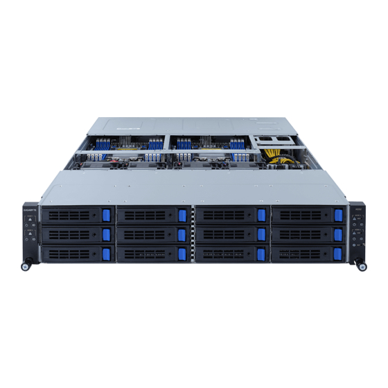
Chapter 2 System Appearance Front View HDD0 HDD3 HDD6 HDD9 HDD1 HDD4 HDD7 HDD10 HDD2 HDD5 HDD8 HDD11 Decription Front Panel LEDs and Buttons • Please Go to Chapter 2-3 Front Panel LED and Buttons for detail description of function LEDs. Rear View PSU2 PSU1... -
Page 20: Front Panel Led And Buttons
Front Panel LED and Buttons NODE1 NODE3 NODE2 NODE4 No. Name Color Status Description Green System is operating normally. Critical condition, may indicates: System fan failure System temperature Amber System Non-critical condition, may indicates: Status LED Blink Redundant power module failure Temperature and voltage issue Non-critical condition, may indicates: Redundant power module failure... -
Page 21: Chapter 2 System Appearance
System LAN LEDs Name Color Status Description Yellow 1Gbps data rate 1GbE Green 100 Mbps data rate Speed LED 10 Mbps data rate Link between system and 1GbE Green network or no access Link/ Blink Data transmission or receiving is occurring Activity LED No data transmission or receiving is occurring - 21 -... -
Page 22: Hard Disk Drive Leds
Hard Disk Drive LEDs LED#1 LED#2 HDD Present RAID SKU HDD Fault Rebuilding LED1 Locate Access (No Access) Disk LED ON(*1) BLINK (*2) Green (LED on Back Panel) Amber No RAID configuration Green ON(*1) (via HBA) Removed HDD Slot (LED on Back Panel) Amber Green BLINK (*2) -
Page 23: Power Supply Unit (Psu) Led
Power Supply Unit (PSU) LED PSU LED State Description Indicates no AC power to all power supplies 1Hz Blink GREEN Indicates AC present/ only standby on/ Cold redundant mode 2Hz Blink GREEN Indicates power supply firmware in updating mode Indicates AC cord unplugged or AC power lost; with a second power supply in parallel still with AC input power Amber Indicates power supply critical event causing shut down:... - Page 24 This page intentionally left blank System Appearance - 24 -...
-
Page 25: Chapter 3 System Hardware Installation
Chapter 3 System Hardware Installation Pre-installation Instructions Computer components and electronic circuit boards can be damaged electrostatic discharge. Working on computers that are still connected to a power supply can be extremely dangerous. Follow the simple guidelines below to avoid damage to your computer or injury to yourself. -
Page 26: Installing The Hard Disk Drive
Installing the Hard Disk Drive Read the following guidelines before you begin to install the Hard disk drive: • Take note of the drive tray orientation before sliding it out. • The tray will not fit back into the bay if inserted incorrectly. •... - Page 27 Follow these instructions to install a 2.5" hard disk drive into 3.5" HDD tray: Press the release button. Extend the locking lever. Pull the locking lever in the direction indicated to remove the HDD tray. Align the hard disk drive with the positioning stub on the HDD tray. Secure the hard disk drive with five screws.
-
Page 28: Removing The Node
Removing the Node Follow these instructions to remove a node: Press the release retaining clip on the right side of the node along the direction of the arrow, Pulling out the node using its handle. Press Pull System Hardware Installation - 26 -... -
Page 29: Removing Chassis Cover
Removing Chassis Cover Before you remove or install the system cover • Make sure the system is not turned on or connected to AC power. Follow these instructions to remove the system cover: Loosen and remove the seven screws securing the middle cover. Slide the cover to the rear of the system and remove the cover in the direction of the arrow. -
Page 30: Removing And Installing The Fan Duct
Removing and Installing the Fan Duct Follow these instructions to remove/install the fan duct: Remove the four screws securing the fan ducts. Lift up to remove the fan ducts To install the fan duct, align the fan duct with the guiding groove. Push down the fan duct into chassis until its firmly seats, then install the four screws to secure the fan ducts in place. -
Page 31: Removing And Installing The Heatsink
Removing and Installing the Heatsink Read the following guidelines before you begin to install the heatsink: • Always turn off the computer and unplug the power cord from the power outlet before installing the heatsink to prevent hardware damage. • Unplug all cables from the power outlets. •... -
Page 32: Installing The Cpu
Installing the CPU Read the following guidelines before you begin to install the CPU: • Make sure that the motherboard supports the CPU. • Always turn off the computer and unplug the power cord from the power outlet before installing the CPU to prevent hardware damage. •... -
Page 33: Installing Memory
Installing Memory Read the following guidelines before you begin to install the memory: • Make sure that the motherboard supports the memory. It is recommended that memory of the same capacity, brand, speed, and chips be used. • Always turn off the computer and unplug the power cord from the power outlet before installing the memory to prevent hardware damage. -
Page 34: Installing The Memory
3-7-2 Installing the Memory Before installing a memory module, make sure to turn off the computer and unplug the power cord from the power outlet to prevent damage to the memory module. Be sure to install DDR4 DIMMs on this motherboard. Follow these instructions to install the Memory: Insert the DIMM memory module vertically into the DIMM slot, and push it down. -
Page 35: Memory Population Table
3-7-4 Memory Population Table • When only one DIMM is used, it must be populated in memory slot DIMM1. EPYC Memory Speed based on DIMM Population (One DIMM per Channel) DIMM Population DIMM Max EPYC 7003 DIMM 0 Type DDR Frequency (MHz) 1R (1 Rank) 3200 RDIMM... -
Page 36: Installing The Pci Expansion Card
Installing the PCI Expansion Card • Voltages can be present within the server whenever an AC power source is connected. This voltage is present even when the main power switch is in the off position. Ensure that the system is powered-down and all power sources have been disconnected from the server prior to installing a PCI card. - Page 37 - 35 - System Hardware Installation...
- Page 38 Follow these instructions to install the right PCI Expansion card: Remove the two screws on the riser bracket to the system. Lift up the riser bracket out of system. Remove the screw securing the side bracket to the riser bracket. Remove the side bracket Align the PCIe card to the riser guide slot and push in the direction of the arrow until the PCIe card sits in the PCI card connector.
-
Page 39: Installing The M.2 Device And Heat Sink
Installing the M.2 Device and Heat Sink WARNING: Installation of the thermal pad over the M.2 device is required when installing an M.2 device. Lack of the thermal pad may result in system overheat and throttle the system performance. CAUTION The position of the stand-off screw will depend on the size of the M.2 device. -
Page 40: Replacing The Fan Module
3-10 Replacing the Fan Module Follow these instructions to replace the fan assembly: Lift up the fan assembly from the chassis. Reverse the previous steps to install the replacement fan assembly. System Hardware Installation - 38 -... -
Page 41: Replacing The Power Supply
3-11 Replacing the Power Supply Follow these instructions to replace the power supply: Pull up the power supply handle and press the retaining clip on the right side of the power supply along the direction of the arrow. At the same time, pull out the power supply by using its handle. Insert the replacement power supply firmly into the chassis. -
Page 42: Cable Routing
3-12 Cable Routing Front Panel IO Rear LAN System Hardware Installation - 40 -... - Page 43 HDD Back Plane Board Power (Top/Bottom Middle Board) HDD Back Plane Board Signal - 41 - System Hardware Installation...
- Page 44 On-Board SATA (Top) SL4_SAS_3 SL4_SAS_1 On-Board SATA (Bottom) SL4_SAS_4 SL4_SAS_2 System Hardware Installation - 42 -...
-
Page 45: Chapter 4 Motherboard Components
Chapter 4 Motherboard Components Motherboard Components DIMM_P0_D0 DIMM_P0_C0 DIMM_P0_B0 DIMM_P0_A0 DIMM_P0_E0 DIMM_P0_F0 DIMM_P0_G0 DIMM_P0_H0 Item Description USB 3.0 Port x 2 ID LED IPMB Connector VGA Port Serial Port Cable Connector GbE LAN Port x 2 Server Management LAN Port M.2 Connector (PCIe3 x4, Supports NGFF-22110) M.2 Connector (PCIe3 x4, Supports NGFF-22110) SlimLine SAS Connector (SL_SATA1/SATA) -
Page 46: Jumper Setting
Jumper Setting NCSI Switch Clear CMOS CLR_CMOS OCP Mezzanine Default Enable Onboard LAN Motherboard Components - 44 -... -
Page 47: Chapter 5 Bios Setup
Chapter 5 BIOS Setup BIOS (Basic Input and Output System) records hardware parameters of the system in the EFI on the motherboard. Its major functions include conducting the Power-On Self-Test (POST) during system startup, saving system parameters and loading operating system, etc. BIOS includes a BIOS Setup program that allows the user to modify basic system configuration settings or to activate certain system features. - Page 48 Main This setup page includes all the items in standard compatible BIOS. Advanced This setup page includes all the items of AMI BIOS special enhanced features. (ex: Auto detect fan and temperature status, automatically configure hard disk parameters.) ...
-
Page 49: The Main Menu
The Main Menu Once you enter the BIOS Setup program, the Main Menu (as shown below) appears on the screen. Use arrow keys to move among the items and press <Enter> to accept or enter other sub-menu. Main Menu Help The on-screen description of a highlighted setup option is displayed on the bottom line of the Main Menu. - Page 50 Parameter Description BIOS Information Project Name Displays the project name information. Project Version Displays version number of the BIOS setup utility. Build Date and Time Displays the date and time when the BIOS setup utility was created. BMC Information BMC Firmware Version Displays version number of the BIOS setup utility.
- Page 51 Parameter Description Total Memory Displays the total memory size of the installed memory. (Note1) Memory Speed Displays the frequency information of the installed memory. (Note1) VR Information Version Displays VR version information. AGESA PI Version PI Version Displays AGESA PI version information. Onboard LAN Information LAN1 MAC Address Displays LAN MAC address information.
-
Page 52: Advanced Menu
Advanced Menu The Advanced menu display submenu options for configuring the function of various hardware components. Select a submenu item, then press [Enter] to access the related submenu screen. BIOS Setup - 50 -... -
Page 53: Trusted Computing
5-2-1 Trusted Computing Parameter Description Configuration Select Enable to activate TPM support feature. Security Device Support Options available: Enable/Disable. Default setting is Enable. SPI TPM Support Options available: Enabled/Disabled. Default setting is Enabled - 51 - BIOS Setup... -
Page 54: Psp Firmware Versions
5-2-2 PSP Firmware Versions The PSP Firmware Versions page displays the basic PSP firmware version information. Items on this window are non-configurable. BIOS Setup - 52 -... -
Page 55: Legacy Video Select
5-2-3 Legacy Video Select Parameter Description Select between onboard or external VGA support. OnBrd/Ext VGA Select Options available: Auto/Onboard/External. Default setting is Onboard. - 53 - BIOS Setup... -
Page 56: Ast2500 Super Io Configuration
5-2-4 AST2500 Super IO Configuration Parameter Description AST2500 Super IO Configuration Super IO Chip Displays the super IO chip information. BIOS Setup - 54 -... - Page 57 Parameter Description Press [Enter] to configure advanced items. Serial Port (Note1) Š – Enable/Disable the Serial Port (COM). When set to Enabled allows you to configure the Serial port 1/2 settings. When set to Disabled, displays no configuration for the serial port. –...
-
Page 58: S5 Rtc Wake Settings
5-2-5 S5 RTC Wake Settings Parameter Description Enable or disable system wake on alarm event. Select Fixed Time, system will wake on the time (HH:MM:SS) specified. Select Dynamic Time and the Wake system from S5 system will wake at the current time plus an increase in minute(s). Options available: Disabled/Fixed Time. -
Page 59: Serial Port Console Redirection
5-2-6 Serial Port Console Redirection Parameter Description Select whether to enable console redirection for specified device. Console COM1/SOL / COM2 Console redirection enables the users to manage the system from a remote location. Redirection (Note) Options available: Enabled/Disabled. Default setting is Disabled. Selects a COM port for Legacy serial redirection. - Page 60 Parameter Description Bits per second Š – Selects the transfer rate for console redirection. – Options available: 9600/19200/38400/57600/115200. Default setting is 115200. Data Bits Š – Selects the number of data bits used for console redirection. – Options available: 7/8. Default setting is 8. Parity Š...
- Page 61 Parameter Description Redirection COM Port Š – Selects a COM port to display redirection of Legacy OS and Legacy OPROM Messages. – Options available: COM1/SOL / COM2. Default setting is COM1/ SOL. Resolution Š Legacy Console Redirection – On Legacy OS, the number of rows and columns supported in Settings redirection.
-
Page 62: Cpu Configuration
5-2-7 CPU Configuration Parameter Description CPU Configuration Enable/disable the CPU Virtualization. SVM Mode Options available: Enabled/Disabled. Default setting is Enabled. Controls the Secure Memory Encryption Enable (SMEE) function. SMEE Options available: Enabled/Disabled. Default setting is Enabled. CPU 0 Information Press [Enter] to view more information related to CPU 0. BIOS Setup - 60 -... -
Page 63: Pci Subsystem Settings
5-2-8 PCI Subsystem Settings - 61 - BIOS Setup... - Page 64 Parameter Description PCI Bus Driver Version Displays the PCI Bus Driver version information. Change the PCIe lanes. SLOT1_F / SLOT1_R / SLOT2_F / Options available: SLOT2_R / SLOT3 / OCP1 / OCP2 Auto / x16 / x8 x8 / x8 x4 x4 / x4 x4 x8 / x4 x4 x4 x4 Lanes (OCP2 Lanes only features Auto / x8 / x4 x4.) (Note1)
-
Page 65: Usb Configuration
5-2-9 USB Configuration Parameter Description USB Configuration USB Module Version Displays the USB version. USB Controllers Displays the supported USB controllers. USB Devices Displays the USB devices connected to the system. Enable/disable the Legacy USB support fuction. AUTO option disables legacy support if no USB devices are connected. - Page 66 Parameter Description USB mass storage device Start Unit command time-out. Device reset time-out Options available: 10 sec/20 sec/30 sec/40 sec. Default setting is 20 sec. Maximum time the device will take before it properly reports itself to the Host Controller. "Auto" uses default value: for a Root port it is 100 ms, for Device power-up delay a Hub port the delay is taken from Hub descriptor.
-
Page 67: Nvme Configuration
5-2-10 NVMe Configuration Parameter Description NVMe controller and Drive Displays the NVMe devices connected to the system. Information - 65 - BIOS Setup... -
Page 68: Sata Configuration
5-2-11 SATA Configuration BIOS Setup - 66 -... -
Page 69: Network Stack Configuration
5-2-12 Network Stack Configuration Parameter Description Enable/Disable the UEFI network stack. Network Stack Options available: Enabled/Disabled. Default setting is Enabled. Enable/Disable the Ipv4 PXE feature. Ipv4 PXE Support (Note) Options available: Enabled/Disabled. Default setting is Enabled. Enable/Disable the Ipv4 HTTP feature. Ipv4 HTTP Support (Note) Options available: Enabled/Disabled. -
Page 70: Uefi Post Logo Configuration
5-2-13 UEFI POST LOGO Configuration Parameter Description UEFI Configuration Select output device. Options available: First loaded Device,Onboard Device,External Device, Output Device Type Specific Device. Default setting is Onboard Deviceevice. BIOS Setup - 68 -... -
Page 71: Amd Mem Configuration Status
5-2-14 AMD Mem Configuration Status Parameter Description Press [Enter] for configuration of advanced items. Channel A/BC/D/E/F/G/H Š – DIMM0 Presence – DIMM1 Presence CPU 0 – Chipset/Bank Interleave Dram EC Š Dram Parity Š Dimm Sensor Fine Grain Mode Š - 69 - BIOS Setup... -
Page 72: Tls Auth Configuration
5-2-15 Tls Auth Configuration Parameter Description Press [Enter] for configuration of advanced items. Enroll Cert Š – Press [Enter] to enroll a certificate • Enroll Cert Using File • Cert GUID Server CA Configuration Input digit character in 1111111-2222-3333-4444- 1234567890ab format. –... -
Page 73: Intel(R) I350 Gigabit Network Connection
5-2-16 Intel(R) I350 Gigabit Network Connection - 71 - BIOS Setup... - Page 74 Parameter Description Press [Enter] to configure advanced items. Link Speed Š – Allows for automatic link speed adjustment. – Options available: Auto Negotiated/10 Mbps Half/10 Mbps Full/100 Mbps Half/100 Mbps Full. Default setting is Auto Negotiated. NIC Configuration Wake On LAN Š...
-
Page 75: Vlan Configuration
5-2-17 VLAN Configuration - 73 - BIOS Setup... - Page 76 Parameter Description Press [Enter] to configure advanced items. Create new VLAN Š VLAN ID Š – Sets VLAN ID for a new VLAN or an existing VLAN. – Press the <+> / <-> keys to increase or decrease the desired values. The valid range is from 0 to 4094.
-
Page 77: Mac Ipv4 Network Configuration
5-2-18 MAC IPv4 Network Configuration Parameter Description Indicates whether network address is configured successfully or not. Configured Options available: Disabled/Enabled. Default setting is Disabled. Enable DHCP Options available: Enabled/Disabled. Default setting is Enabled. (Note) Local IP Address Press [Enter] to configure local IP address. (Note) Local NetMask Press [Enter] to configure local NetMask. -
Page 78: Mac Ipv6 Network Configuration
5-2-19 MAC IPv6 Network Configuration Parameter Description Press [Enter] for configuration of advanced items. Interface Name Š Interface Type Š MAC address Š Host address Š Route Table Š Gateway addresses Š DNS addresses Š Interface ID Š Enter Configuration Menu –... -
Page 79: Amd Cbs Menu
AMD CBS Menu AMD CBS menu displays submenu options for configuring the CPU-related information that the BIOS automatically sets. Select a submenu item, then press [Enter] to access the related submenu screen. - 77 - BIOS Setup... -
Page 80: Cpu Common Options
5-3-1 CPU Common Options Parameter Description Valhalla Common Options Press [Enter] for more options. Custom Core Pstates Š – Allows you to accept or decline custom core pstates. When accepted you can disable or customize ceratin pstates. Performance CCD/Core/Thread Enablement Š... - Page 81 Parameter Description From a workaroud for GCC/C000005 issue for XV Core on CZ A0, setting MSRC001_1029 Decode Configuration (DE_CFG) bit 14 RedirectForReturnDis [DecfgNoRdrctForReturns] to 1. Options available: Auto/1/0. Default option is Auto. Enable/Disable PFEH, cloak individual banks, and mask deferred error Platform First Error Warning interrupts from each bank.
- Page 82 Parameter Description By default (Auto) the bronze workaround is applied. Bronze workaround: DbReq and PDM function as expected, breakpoint redirect capability compromised. Xtrig7 Workaround Silver workaround: DbReq, PDM, and breakpoint redirect function as expected, SCAN capability compromised. Options available: Auto/No Workaround/Bronze Workaround/Silver Workaround.
-
Page 83: Df Common Options
5-3-2 DF Common Options Parameter Description Press [Enter] for configuration of advanced items. DRAM scrub time Š – Provides a value that is the number of hours to scrub memory. – Options available: Disabled/1 hour/4 hours/8 hours/16 hours/24 hours/48 hours/Auto. Default option is Auto. Poison scrubber control Š... - Page 84 Parameter Description Press [Enter] for more options. NUMA notes per socket Š – Specifies the number of desired NUMA (Non-uniform Memory Access) notes per socket. Zero will attempt to interleave the two sockets together. – Options available: NPS0/NPS1/NPS2/NPS4/Auto. Default option is Auto.
- Page 85 Parameter Description Press [Enter] for more options. GMI encryption control Š – Control GMI link encryption. – Options available: Disable/Enable/Auto. Default option is Auto. xGMI encryption control Š – Control xGMI link encryption.Options available: Disable/Enable/ Auto. Default option is Auto. CAKE CRC perf bounds control Š...
-
Page 86: Umc Common Options
5-3-3 UMC Common Options Parameter Description Press [Enter] for more options. Enforce POR Š – Press [Enter] to configure the enforcement of Plan Of Record (POR) which enables enforcement of POR restrictions for DDR4 frequency and voltage programming. DRAM Controller Configuration Š... - Page 87 Parameter Description Press [Enter] for more options Chipselect Interleaving Š – Interleave memory blocks across the DRAM chip slects for node 0 – Options available: Disabled/Auto. Default option is Auto. BankGroupSwap Š – Configures the BankGroupSwap. BankGroupSwap (BGS) is a memory mapping option in AGESA that alters how applications get assigned to physical locations within the memory modules.
-
Page 88: Nbio Common Options
5-3-4 NBIO Common Options Parameter Description NBIO Common Options Enable/Disable IOMMU. IOMMU Options available: Enabled/Disabled. Default setting is Disabled. AER must be enabled for ACS enable to work. ACS Enable Options available: Enable/Disabled/Auto. Default option is Auto. Enables Alternative Routing ID Interpretation. PCIe ARI Support Options available: Disable/Enable/Auto. - Page 89 Parameter Description Press [Enter] for more options. Determinism Control Š – Auto = Use the fused determinism, Manual = User can set customized determinism. – Options available: Manual/Auto. Default option is Manual. cTDP Control Š – Auto = Use the fused TDP, Manual = User can set customized TDP.
- Page 90 Parameter Description Press [Enter] for more options. NBIO RAS Global Control Š – Options available: Manual/Auto. Default option is Auto. NBIO RAS Control Š – 0 = Disabled, 1 = MCA, 2 = Legacy. – Options available: Disabled/MCA/Legacy. Default option is MCA. Egress Poison Severity High Š...
- Page 91 Parameter Description System Hub Watchdog Timer Š – Enter a value. This value specifies the timer interval of the SYSHUB watchdog timer in miliseconds. SLINK Read Response OK Š – This value specifies whether SLINK read response errors are converted to an Okay response. When this value is set to TRUE, read response errors are converted to Okay responses with data of all FFs.
- Page 92 Parameter Description Sync Flood on PCIe Fatal Error Š – When 'Sync Flood on PCIe Fatal Error' is True, PcdAmdPcieSyncFloodOnFatal should be set to True. When 'Sync NBIO RAS Common Options Flood on PCIe Fatal Error' is False, PcdAmdPcieSyncFloodOnFatal (continued) should be set to False.
-
Page 93: Fch Common Options
5-3-5 FCH Common Options Parameter Description FCH Common Options SATA Enable Š – Enable or disable OnChip SATA controller. – Options available: Disabled/Enabled/Auto. Default setting is Auto. SATA RAS Support Š – Enable or disable SATA RAS support. – Options available: Disabled/Enabled/Auto. Default setting is Auto. SATA Configuration Options Sata Disabled AHCI Prefetch Function Š... - Page 94 Parameter Description Press [Enter] for more options. XHCI Controller0 Enable Š – Enable or disable USB3 controller. – Options available: Enabled/Disabled/Auto. Default setting is Auto. XHCI Controller1 Enable Š USB Configuration Options – Enable or disable USB3 controller. – Options available: Enabled/Disabled/Auto. Default setting is Auto. USB ecc SMI Enable Š...
- Page 95 Parameter Description Press [Enter] for more options. eMMC/SD Configure Š – Options available: Disabled/SD Normal Speed/SD High Speed/SD UHSI-SDR50/SD UHSI-DDR50/SDUHSI-SDR104/eMMC Emmc Backward Compatibility/eMMC High Speed SDR/eMMC High Speed DDR/eMMC HS200/eMMCHS400/eMMC HS300/Auto. Default setting is Auto. eMMC Options Driver Type Š –...
-
Page 96: Ntb Common Options
5-1-1 NTB Common Options Parameter Description NTB Common Options Enable or disable OnChip SATA controller. NTB Enable Options available: Auto/Enable. Default setting is Auto. BIOS Setup - 94 -... -
Page 97: Soc Miscellaneous Control
5-1-1 SOC Miscellaneous Control Parameter Description Soc Miscellaneous Control Enable = Enable ConsoleOut Function for ABL Disable = Disable ConsoleOut Function for ABL ABL Console Out Control Auto = Keep default behavior Options available: Disable/Enable/Auto. Default setting is Auto. - 95 - BIOS Setup... -
Page 98: Amd Pbs Option Menu
AMD PBS Option Menu AMD PBS Option menu displays submenu options for configuring the function of AMD PBS. Select a submenu item, then press [Enter] to access the related submenu screen. Parameter Description AMD PBS Press [Enter] for advanced configurations. Enable or disable SPI Locking for protect ROM part. -
Page 99: Ras
5-1-1 RAS Parameter Description Enable or disable Periodic SMI for polling [MCA Threshold] error. RAS Periodic SMI Control Options Available: Disabled/Enabled. Default option is Enabled. Enter a value. Limits the number of [MCA Threshold and Deferred Error SMI source] SMI Threshold per a unit of time (Defined by [SMI Scale]). - Page 100 Parameter Description PCIe UnCorr GHES Notify Notification type for PCIe uncorrected errors. Type Options Available: Polled/NMI. Default option is NMI. PCIe Root Port Corr Err Mask Enter a value. Intialize the PCIe AER Corrected Error Mask register of Root Port. PCIe Root Port UnCorr Err Enter a value.
-
Page 101: Chipset Setup Menu
Chipset Setup Menu Chipset Setup menu displays submenu options for configuring the function of the SoC. Select a submenu item, then press [Enter] to access the related submenu screen. Parameter Description PCIe Link training in 1 or 2 steps. PCIe Link Training Type Options available: 1 Step/2Step. -
Page 102: Server Management Menu
Server Management Menu Parameter Description FRB-2 Timer FRB-2 timer (POST timer). Configure the FRB2 Timer timeout. Options available: 3 minutes/4 minutes/5 minutes/6 minutes. Default setting is 6 FRB-2 Timer minutes. timeout (NOTE) This item is configurable when FRB-2 Timer is set to Enabled. Configure the FRB2 Timer policy. - Page 103 Parameter Description View FRU Press [Enter] to view the advanced items. Information BMC network Press [Enter] to configure advanced items. configuration IPv6 BMC Network Press [Enter] to configure advanced items. Configuration - 101 - BIOS Setup...
-
Page 104: System Event Log
5-6-1 System Event Log Parameter Description Enabling / Disabling Options Change this item to enable or disable all features of System Event SEL Components Logging during boot. Options available: Enabled/Disabled. Default setting is Enabled. Erasing Settings Choose options for erasing SEL. Erasing SEL Options available: No/Yes, On next reset/Yes, On every reset. -
Page 105: View Fru Information
5-6-2 View FRU Information The FRU page is a simple display page for basic system ID information, as well as System product information. Items on this window are non-configurable. (Note) The model name will vary depends on the product you purchased. - 103 - BIOS Setup... -
Page 106: Bmc Network Configuration
5-6-3 BMC Network Configuration Parameter Description BMC network configuration Lan Channel 1 Select to configure LAN channel parameters statically or dynamically (DHCP). Do nothing option will not modify any BMC network parameters Configuration Address source during BIOS phase. Options available: Unspecified/Static/DynamicBmcDhcp. Default setting is DynamicBmcDhcp. -
Page 107: Ipv6 Bmc Network Configuration
5-6-4 IPv6 BMC Network Configuration Parameter Description IPv6 BMC Network Configuration IPv6 BMC Lan Channel 1 Enable/Disable IPv6 BMC LAN channel function. When this item is IPv6 BMC Lan Option disabled, the system will not modify any BMC network during BIOS phase. Options available: Unspecified/Disable/Enable. -
Page 108: Security Menu
Security Menu The Security menu allows you to safeguard and protect the system from unauthorized use by setting up access passwords. There are two types of passwords that you can set: • Administrator Password Entering this password will allow the user to access and change all settings in the Setup Utility. •... -
Page 109: Secure Boot
5-7-1 Secure Boot Parameter Description System Mode Displays the system is in User mode or Setup mode. Enables/Disables Secure Boot. The mode change requires a platform Secure Boot reset. Options available: Disabled/Enabled. Default setting is Disabled. Secure Boot requires all the applications that are running during the booting process to be pre-signed with valid digital certificates. - Page 110 Parameter Description Factory Key Provision Š – Installs factory default Secure Boot keys after the platform resets and the system is in Setup Mode. – Options available: Disabled/Enabled. Default setting is Disabled. Restore Factory Keys Š – Installs factory default Secure Boot key databases. It will force the system in User Mode.
-
Page 111: Boot Menu
Boot Menu The Boot menu allows you to set the drive priority during system boot-up. BIOS setup will display an error message if the legacy drive(s) specified is not bootable. Parameter Description Boot Configuration Number of seconds to wait for setup activation key. 65535 (0xFFFF) Setup Prompt Timeout means indefinite waiting. - Page 112 Parameter Description UEFI Network Drive BBS Press [Enter] to configure the boot priority. Priorities UEFI Application Boot Priorities Press [Enter] to configure the boot priority. BIOS Setup - 110 -...
-
Page 113: Uefi Network Drive Bbs Priorities
5-8-1 UEFI NETWORK Drive BBS Priorities The UEFI network drive BBS priorities submenu allows you to specify the boot device priority from the available UEFI network drives during system boot-up. BIOS setup will display an error message if the legacy drive(s) specified is not bootable. -
Page 114: Uefi Application Boot Priorities
5-8-2 UEFI Application Boot Priorities The UEFI application boot priorities submenu allows you to specify the boot device priority from the available UEFI applications during system boot-up. BIOS setup will display an error message if the legacy drive(s) specified is not bootable. BIOS Setup - 112 -... -
Page 115: Save & Exit Menu
Save & Exit Menu The Exit menu displays the various options to quit from the BIOS setup. Highlight any of the exit options then press [Enter]. Parameter Description Save Options Saves changes made and closes the BIOS setup. Save Changes and Exit Options available: Yes/No. - Page 116 5-10 BIOS POST Beep code (AMI standard) 5-10-1 PEI Beep Codes # of Beeps Description Memory not Installed. Memory was installed twice (InstallPeiMemory routine in PEI Core called twice) Recovery started DXEIPL was not found DXE Core Firmware Volume was not found Recovery failed S3 Resume failed Reset PPI is not available...