
Related Manuals for Lite-on Tech NA115


Summary of Contents for Lite-on Tech NA115
- Page 1 NA115 Intel® 845 Motherboard USER’S MANUAL Intel® Pentium®4 Willamette/Northwood Processor Motherboard Rev. 1.0...
- Page 2 NA115 Motherboard Revision History Revision Date Description Initial release of NA115 motherboard user’s manual Item Checklist 1 NA115 Motherboard 1 Floppy Cable 1 ATA Cable 66/100 1 I/O Shield 1 Heatsink Retention Module 1 CD for Motherboard Driver NA115 User Manual Quick Installation Guide Intel®...
- Page 3 NA115 Motherboard Safety Instructions Please follow some precautions when operating your computer. 1. Always unplug the power cord when inserting any add-on card or module inside the system. 2. Use a grounded wrist strap before handling computer components. If one is not available, touch both of your your hands to a safely grounded object or to a metal object.
-
Page 4: Table Of Contents
NA115 Motherboard Table of Contents Chapter 1. Introduction …………………………………………………………………… 1 Motherboard Specification …………………………………………………………………………. 1 NR115 Motherboard Layout …………………………………………………………………….…. 3 Chapter 2. Hardware Installation Process ……………………………………….. 4 Installing Central Process Unit (CPU) …………………………………………………………….. 4 Installing Memory Modules ………………………………………………………………………… 6 Connecting IDE and Floppy Disk Cables and Drives …………………………………………… 7 Installing Expansion Cards …………………………………………………………………………... -
Page 5: Chapter 1 Introduction
NA115 Motherboard Chapter 1 Introduction Motherboard Specifications Form Factor: • ATX Form Factor • Size 12” x 9.6” (30.5cm x 24.4cm) Processor: • Socket mPGA478B • Intel® Pentium® 4 Willamette/Northwood. System Memory: • 2 DIMM Sockets support up to 2GB. - Page 6 NA115 Motherboard IDE Ports: • Promise PDC20265R ATA-100 RAID controller • 4 IDE ports support up to 8 devices • Support Ultra DMA 33/66/100 On Board I/O: • ATX power connector. • +12V power connector. • Aux power connector (option).
-
Page 7: Nr115 Motherboard Layout
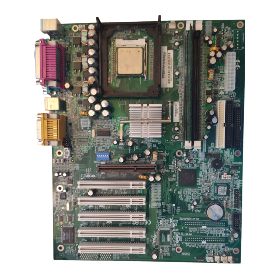
NA115 Motherboard NA115 Motherboard Layout CPU Socket Front Side USB CPU Fan Socket ATA-100 Raid IDE Connector Memory Sockets Expansion Slots Power Supply Connector Audio Connector Floppy Connector Back Panel Connectors IDE Connectors Front Side Bus Frequency Selector Front Panel Connector... -
Page 8: Chapter 2 Hardware Installation Process
NA115 Motherboard Chapter 2 Hardware Installation Process Installing the Central Process Unit (CPU) CPU Installation 1. Unlock the CPU socket by pulling the lever up to a 90-degree angle. 2. Position the CPU above the socket such that the marked corner (pin1) matches the corner near the base of the lever. - Page 9 NA115 Motherboard Installing the Central Process Unit (CPU) cont. CPU Heat Sink Installation 1. Read the related CPU heat sink user’s manual for more detailed installation procedures. 2. Connect CPU fan power cable into the CPU fan connector on the motherboard.
-
Page 10: Installing Memory Modules
NA115 Motherboard Installing Memory Modules 1. Push the white retaining clips on each of the memory socket outwards. 2. Match the notches on the contact edge of the memory module to the ridges in the memory socket. 3. Insert the memory module vertically into place. When properly inserted, the white retaining clips will move inward to lock in the module. -
Page 11: Connecting Ide And Floppy Disk Cables And Drives
NA115 Motherboard Connecting IDE and Floppy Disk Cables 1. Connecting the floppy disk ribbon cable into the motherboard. The side of the cable with the red stripe needs to be inserted into the Pin1 side of the floppy disk connector. - Page 12 NA115 Motherboard Connect Floppy and IDE Drives NOTE: If installing two IDE devices on the same ribbon cable, one device is to be set as “master” and the second as “slave”. Please refer to IDE device manuals for master and slave settings.
-
Page 13: Installing Expansion Cards
NA115 Motherboard Installing Expansion Cards 1. Read the related expansion card’s installation instructions before inserting the expansion card into the motherboard. 2. Remove the slot covers from the chassis case where the expansion cards will be placed. 3. Press the expansion card firmly into the expansion slot of the motherboard. -
Page 14: Connect Power Supply Cable
NA115 Motherboard Connect the Power Supply Cables NOTE: The ATX power connector is keyed for proper insertion. 1. Place the plastic clip of the power connector over the plastic tab on the motherboard power connector. The plastic clip should lock into the plastic tab. -
Page 15: I/O Back Panel Introduction
NA115 Motherboard I/O Back Panel Introduction (1) PS/2 Keyboard and PS/2 Mouse Connector PS/2 Mouse Connector (6 pin Female) PS/2 Keyboard Connector (6 pin Female) This connector supports standard PS/2 keyboard and PS/2 mouse. (2) Parallel Port and Serial Ports (COM1/COM2) - Page 16 NA115 Motherboard I/O Back Panel Introduction cont…. (3) USB Connector USB 1 USB 2 Before connecting device(s) into the USB connections, determine if devices have a standard interface. Make sure your computer Operating System (OS) supports the USB controller. If not, contact your OS or device(s) vendors for more information.
-
Page 17: Jumpers Introduction
NA115 Motherboard Jumper Introduction Jumper Settings The following graphic shows the meaning of the jumper with cover and without cover. PIN 1 PIN 1 ON (1-2) FWH Lock This jumper allows you to set FWH lock. Reference: Connector Type: 1 x 3... - Page 18 NA115 Motherboard cont. Jumper Introduction Clear CMOS (Optional) This jumper allows you to clear the content of the CMOS. Reference: Connector Type: 1 x 3 Description Jumper Placement Normal Put the jumper cover on pin1 and pin2. Clear content of CMOS Put the jumper cover on pin2 and pin3.
- Page 19 NA115 Motherboard Jumper Introduction cont. The following table shows the Front Side Bus Frequency Selector settings. Front Side Bus Frequency Selector FSB SELECT SEL1 SEL2 SEL3 SEL4 SEL5 SEL6 AUTO 100MHZ 102MHZ 105MHZ 108MHZ 111MHZ 114MHZ 117MHZ 120MHZ 123MHZ 126MHZ...
- Page 20 NA115 Motherboard Jumper Settings cont. The following table shows the Front Side USB Connector Pin Definition. USB1+ USB2+ USB2- USB1- GND2 GND1 USBOC Front Side USB Connector Pin Definition Signal Name Description Front Side USB Port2 VCC Front Side USB Port1 VCC...
-
Page 21: Chapter 3. Ami® Bios Setup
To navigate through the menu, simply use the arrow keys to select among the items and press <Enter> to accept or enter the sub-menu. AMI HIFLEX SETUP UTILITY - VERSION 1.38 ©2001 AMERICAN MEGATRENDS, INC. ALL RIGHTS RESERVED NA115 BIOS Rev: 0.00.02 Standard CMOS Features Advanced... -
Page 22: Standard Cmos Setup
NA115 Motherboard Standard CMOS Setup The items listed in the Standard CMOS Features Menu may include no or more than one setup items. Use the arrow keys to navigate through the menu and use the <PgUp> or<PgDn> keys to select the desired value for each item. -
Page 23: Advanced Cmos Setup
NA115 Motherboard Advanced CMOS Setup The items listed in the Advanced CMOS Features Menu may include no or more than one setup items. Use the arrow keys to navigate through the menu and use the <PgUp> or<PgDn> keys to select the desired option for each item. -
Page 24: Advanced Chipset Setup
NA115 Motherboard Advanced Chipset Setup The items listed in the Advanced Chipset Setup Menu may include no or more than one setup items. Use the arrow keys to navigate through the menu and use the <PgUp> or<PgDn> keys to select the desired option for each item. -
Page 25: Power Management Setup
NA115 Motherboard Power Management Setup The items listed in the Power Management Setup Menu may include no or more than one setup items. Use the arrow keys to navigate through the menu and use the <PgUp> or<PgDn> keys to select the desired option for each item. -
Page 26: Pci/Plug And Play Setup
NA115 Motherboard PCI/Plug and Play Setup The items listed in the PCI/Plug and Play Setup Menu may include no or more than one setup items. Use the arrow keys to navigate through the menu and use the <PgUp> or<PgDn> keys to select the desired option for each item. -
Page 27: Peripheral Setup
NA115 Motherboard Peripheral Setup The items listed in the Peripheral Setup Menu may include no or more than one setup items. Use the arrow keys to navigate through the menu and use the <PgUp> or<PgDn> keys to select the desired option for each item. -
Page 28: Hardware Monitor Setup
NA115 Motherboard Hardware Monitor Setup The items listed in the Hardware Monitor Setup may include no or more than one setup items. Use the arrow keys to navigate through the menu and use the <PgUp> or<PgDn> keys to select the desired option for each item. -
Page 29: Auto-Detect Hard Disks
NA115 Motherboard Auto-Detect Hard Disk The items listed in the Auto-Detect Hard Disk Menu may include no or more than one setup items. Use the arrow keys to navigate through the menu and use the <PgUp> or<PgDn> keys to select the desired option for each item. -
Page 30: Change User Password
<PgUp> or<PgDn> keys to select the desired option for each item. AMI HIFLEX SETUP UTILITY - VERSION 1.38 ©2001 AMERICAN MEGATRENDS, INC. ALL RIGHTS RESERVED NA115 BIOS Rev: 0.00.02 Standard CMOS Features Advanced... -
Page 31: Change Supervisor Password
<PgUp> or<PgDn> keys to select the desired option for each item. AMI HIFLEX SETUP UTILITY - VERSION 1.38 ©2001 AMERICAN MEGATRENDS, INC. ALL RIGHTS RESERVED NA115 BIOS Rev: 0.00.02 Standard CMOS Features Advanced... -
Page 32: Auto Configuration With Optimal Settings
Use the arrow keys to navigate through the menu and use the <PgUp> or<PgDn> keys to select the desired option for each item. AMI HIFLEX SETUP UTILITY - VERSION 1.38 ©2001 AMERICAN MEGATRENDS, INC. ALL RIGHTS RESERVED NA115 BIOS Rev: 0.00.02 Standard CMOS Features Advanced... -
Page 33: Auto Configuration With Fail Safe Settings
Use the arrow keys to navigate through the menu and use the <PgUp> or<PgDn> keys to select the desired option for each item. AMI HIFLEX SETUP UTILITY - VERSION 1.38 ©2001 AMERICAN MEGATRENDS, INC. ALL RIGHTS RESERVED NA115 BIOS Rev: 0.00.02 Standard CMOS Features Advanced... -
Page 34: Save Settings And Exit
<PgUp> or<PgDn> keys to select the desired option for each item. AMI HIFLEX SETUP UTILITY - VERSION 1.38 ©2001 AMERICAN MEGATRENDS, INC. ALL RIGHTS RESERVED NA115 BIOS Rev: 0.00.02 Standard CMOS Features Advanced... -
Page 35: Exit Without Saving
<PgUp> or<PgDn> keys to select the desired option for each item. AMI HIFLEX SETUP UTILITY - VERSION 1.38 ©2001 AMERICAN MEGATRENDS, INC. ALL RIGHTS RESERVED NA115 BIOS Rev: 0.00.02 Standard CMOS Features Advanced... - Page 36 NA115 Motherboard NOTES...