
Related Manuals for Lite-on Tech NA280


Summary of Contents for Lite-on Tech NA280
- Page 1 NA280 VIA® P4X266A Motherboard USER’S MANUAL Pentium®4 Processor Motherboard Rev. 1.0...
- Page 2 NA280 Motherboard...
- Page 3 NA280 Motherboard Revision History Revision Date Description Initial release of NA280 motherboard user’s manual Item Checklist 1 NA280 Motherboard 1 Floppy Cable 1 ATA Cable 66/100 1 I/O Shield 1 Heatsink Retention Module 1 CD for Motherboard Driver 1 NA280 Quick Installation Guide 1 NA280 User Manual Intel®...
- Page 4 NA280 Motherboard Safety Instructions Follow these precautions when operating your computer. 1. Always unplug the power cord when inserting any add-on card or module inside the system. 2. Wear a grounding strap attached to a grounded device to avoid damage from static electricity. If one is not available, discharge static electricity by touching the metal case of a safely grounded object before working on the motherboard.
-
Page 5: Table Of Contents
NA280 Motherboard Table of Contents Motherboard Specifications ................1 NA280 Motherboard Layout................6 Installing the Central Process Unit (CPU)...........9 Installing Memory Modules ...............11 Connecting IDE and Floppy Disk Cables..........13 Connecting Floppy and IDE Drives............14 Installing Expansion Cards ...............16 Connecting the Power Supply Cables ............17 Jumper Introduction ..................21... - Page 6 NA280 Motherboard...
-
Page 7: C C I I
NA280 Motherboard Motherboard Specifications Form Factor: • Standard ATX 305 x 244 mm Processor: • Supports single Intel Pentium 4 Processor in 478 ball FC- PGA2 package • Processor socket mPGA478B • 533 MHz system bus Cache Memory: • Processor integrated level-1 and level-2 cache System Memory: •... - Page 8 NA280 Motherboard Core Logic Chipset: • High performance Northbridge 533 MHz front side bus plus AGP 4x external bus • 64-bit Advanced ECC Memory controller supporting PC2100/PC1600 DDR • Combines VIA VT8233A V-Link Southbridge for integrated LAN, audio, ATA133 IDE, and four USB ports •...
- Page 9 NA280 Motherboard Audio: • Complies with AC ‘97 v2.2 specification • AC-link interface for AC ‘97 audio codec and modem codec • Integrated SoundBlasterPro/DirectSound compatible digital audio controller • 18-bit stereo full-duplex CODEC with independent and variable sampling rate •...
- Page 10 NA280 Motherboard On board I/O: • Low Pin Count (LPC) interface • Two serial ports – DB9 (16550 UART) • One parallel port – DB25 with ECP/EPP support • One PS/2 mouse connector • One PS/2 keyboard connector • Two PWM fan controlled output headers •...
- Page 11 NA280 Motherboard Other: • Front panel I/O 2X5 header, key pin 10 • On-board buzzer...
-
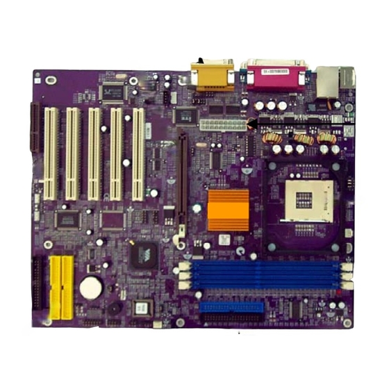
Page 12: Na280 Motherboard Layout
NA280 Motherboard NA280 Motherboard Layout Power Supply Connector Floppy Connector CPU Socket PCI Expansion Slots CPU Fan Connector CNR Slot Memory Sockets AGP Slot IDE Connectors Audio Connector Front Panel Connectors Back Panel Connectors RAID Connectors... - Page 13 NA280 Motherboard Front Panel Connector Pin Definition LPANEL 1 Pin Signal Name Pin Signal Name HLED+ HLED- PLEDY- SPKR VCC PLEDG- SPKR GND PLED+ SPKR GND SPKR PS GND RESET RESET GND PANEL1 Pin Signal Name Pin Signal Name HD_LED_P...
-
Page 15: Chapter 2 Hardware Installation Process
NA280 Motherboard Chapter 2 Hardware Installation Process Installing the Central Process Unit (CPU) CPU Installation 1. Unlock the CPU socket by pulling the locking lever up to a 90- degree angle. 2. Position the CPU above the socket so that its marked corner (pin1) matches the corner near the base of the lever. - Page 16 NA280 Motherboard CPU Heat Sink Installation 1. Read the related CPU heat sink user’s manual for more detailed installation procedures. 2. Connect the CPU fan power cable to the CPU fan connector on the motherboard. CPU fan power cable CPU fan...
-
Page 17: Installing Memory Modules
NA280 Motherboard Installing Memory Modules 1. Push the white retaining clips on the memory socket outwards. 2. Match the notches on the contact edge of the memory module to the ridge in the memory socket. 3. Insert the memory module vertically into place. When properly inserted, the white retaining clips will move inward to lock in the module. - Page 18 NA280 Motherboard Total Memory Sizes with Unbuffered DDR SDRAM DIMM DIMM Type 1 DIMMx64/x72 2 DIMMsx64/x72 3 DIMMsx64/x72 64 Mbit 128 MBytes 256 MBytes 384 MBytes (2Mx8x4 banks) 64 Mbit 64 MBytes 128 MBytes 192 MBytes (1Mx16x4 banks) 128 Mbit...
-
Page 19: Connecting Ide And Floppy Disk Cables
NA280 Motherboard Connecting IDE and Floppy Disk Cables Connecting the floppy disk ribbon cable into the motherboard. The side of the cable with the red stripe needs to be inserted into the Pin1 side of the floppy disk connector. Pin1 is marked with a white triangle. -
Page 20: Connecting Floppy And Ide Drives
NA280 Motherboard Connecting Floppy and IDE Drives Follow these instructions to connect a floppy disk drive (FDD) and IDE drive to your motherboard. Floppy Disk Drive 1. Mount the drive into the case. 2. Connect the floppy disk ribbon cable and power cable to the FDD. - Page 21 NA280 Motherboard Hard Disk Drive NOTE: If installing two IDE devices on the same ribbon cable, one device is to be set as “master” and the second as “slave”. Refer to the IDE device manual for master and slave settings.
-
Page 22: Installing Expansion Cards
NA280 Motherboard Installing Expansion Cards 1. Read the related expansion card’s installation instructions before inserting the expansion card into the motherboard. 2. Remove the slot cover from the chassis case where the expansion card will be placed. 3. Press the expansion card firmly into the expansion slot of the motherboard. -
Page 23: Connecting The Power Supply Cables
NA280 Motherboard Connecting the Power Supply Cables Connect the power connector to the motherboard power connector. The plastic clip on the connector should lock into the plastic tab on the motherboard connector. Power Supply Connector NOTE: The ATX power connector is keyed for proper insertion. - Page 24 NA280 Motherboard I/O Back Panel Introduction (1) PS/2 Keyboard and PS/2 Mouse Connector PS/2 Mouse Connector (6-pin Female) PS/2 Keyboard Connector (6-pin Female) This connector supports a standard PS/2 keyboard and PS/2 mouse. (2) RJ-45 LAN Connector LAN Connector (8-pin RJ-45)
- Page 25 NA280 Motherboard (3) Parallel Port Parallel Port (25-pin Female) Devices such as a printer can be connected to the parallel port. (4) Game Port Game Port (15-pin Female) This connector supports a joystick, MIDI keyboard and other related audio devices.
- Page 26 NA280 Motherboard (6) Serial Connector Serial Port – COM1 (9-pin Female) Devices such as a mouse or modem can be connected to the serial port. The serial port is identified by the system as COM1. (7) USB Connector USB Connector Before connecting a device to the USB connectors, determine if the device has a standard USB interface.
-
Page 27: Jumper Introduction
NA280 Motherboard Jumper Introduction Jumper Settings The following graphic shows the meaning of the jumper with cover and without cover. ON (1-2) - Page 28 NA280 Motherboard Clear CMOS This jumper allows you to clear the CMOS. Reference: JP1 (3-pin) Jumper setting Description Normal operation Clear content of CMOS BIOS Protect This jumper allows you protect the BIOS from being accidentally updated. Reference: JP2 (3-pin)
- Page 29 NA280 Motherboard CPU Frequency Select This jumper allows you to set the CPU frequency. Reference: JP3 (3-pin) Jumper setting Description Auto 133 MHz CPU Frequency Select This jumper allows you to set the CPU voltage. Reference: JP4 (3 x 3-pin)
- Page 30 NA280 Motherboard WARNING! It is recommended that you do not change the settings on Jumper 4. Overclocking components can adversely affect the reliability of the system and introduce errors into your system. Overclocking can permanently damage the mainboard by generating excess heat in components that are run beyond the rated limits.
-
Page 31: Chapter 3: Award® Bios Setup
NA280 Motherboard Chapter 3: Award® BIOS Setup Entering the Setup Utility When you power on the system, BIOS enters the Power-On Self Test (POST) routines. POST is a series of built-in diagnostics performed by the BIOS. After the POST routines are completed, the following message... -
Page 32: Standard Cmos Features
NA280 Motherboard Standard CMOS Features This option displays basic information about your system. Use the arrow keys to navigate through the menu and use the <PgUp> and <PgDn> to select the desired value for each item. CMOS Setup Utility – Copyright (C) 1984 – 2001 Award Software... -
Page 33: Advanced Bios Setup Option
NA280 Motherboard Advanced BIOS Setup Option This option displays advanced information about your system. Use the arrow keys to navigate through the menu and use the <PgUp> and <PgDn> to select the desired value for each item. CMOS Setup Utility – Copyright (C) 1984 – 2001 Award Software... -
Page 34: Advanced Chipset Features Option
NA280 Motherboard Advanced Chipset Features Option These items define critical timing parameters of the motherboard. You should leave the items on this page at their default values unless you are very familiar with the technical specifications of your system hardware. If you change the values incorrectly, you may introduce fatal errors or recurring instability into your system. - Page 35 NA280 Motherboard DRAM Clock/Drive Control Scroll to this item and press <Enter> to view the following screen: CMOS Setup Utility – Copyright (C) 1984 – 2001 Award Software DRAM Clock/Drive Control Item Help Current FSB Frequency Current DRAM Frequency Menu Level...
- Page 36 NA280 Motherboard AGP & P2P Bridge Control Scroll to this item and press <Enter> to view the following screen: CMOS Setup Utility – Copyright (C) 1984 – 2001 Award Software AGP & P2P Bridge Control Item Help AGP Aperture Size...
- Page 37 NA280 Motherboard CPU & PCI Bus Control Scroll to this item and press <Enter> to view the following screen: CMOS Setup Utility – Copyright (C) 1984 – 2001 Award Software CPU & PCI Bus Control Item Help CPU to PCI Write Buffer...
-
Page 38: Integrated Peripherals Option
NA280 Motherboard Integrated Peripherals Option These items define the operation of peripheral components on the system's input/output ports. Use the arrow keys to navigate through the menu and use the <PgUp> and <PgDn> to select the desired value for each item. - Page 39 NA280 Motherboard VIA OnChip IDE Device Scroll to this item and press <Enter> to view the following screen: CMOS Setup Utility – Copyright (C) 1984 – 2001 Award Software VIA OnChip IDE Device Item Help OnChip IDE Channel 0 [Enabled]...
- Page 40 NA280 Motherboard VIA OnChip PCI Device Scroll to this item and press <Enter> to view the following screen: CMOS Setup Utility – Copyright (C) 1984 – 2001 Award Software VIA OnChip PCI Device Item Help VIA-3058 AC97Audio [Auto] VIA-3068 MC97 Modem...
- Page 41 NA280 Motherboard SuperIO Device Scroll to this item and press <Enter> to view the following screen: CMOS Setup Utility – Copyright (C) 1984 – 2001 Award Software SuperIO Device Item Help Onboard FDC Controller [Enabled] Onboard Serial Port 1 [3F8/IRQ4]...
-
Page 42: Power Management Setup Option
NA280 Motherboard Power Management Setup Option These items setup power management options for the motherboard. Use the arrow keys to navigate through the menu and use the <PgUp> and <PgDn> to select the desired value for each item. CMOS Setup Utility – Copyright (C) 1984 – 2001 Award Software... - Page 43 NA280 Motherboard IRQ/Event Activity Detect Scroll to this item and press <Enter> to view the following screen: CMOS Setup Utility – Copyright (C) 1984 – 2000 Award Software IRQ/Event Activity Detect Item Help PS2KB Wakeup from S3/S4/S5 [Disable] USB Resume from S3...
-
Page 44: Pnp/Pci Configuration Option
NA280 Motherboard PNP/PCI Configuration Option These options configure how PnP (Plug and Play) and PCI expansion cards operate in your system. Use the arrow keys to navigate through the menu and use the <PgUp> and <PgDn> to select the desired value for each item. -
Page 45: Pc Health Status Option
NA280 Motherboard PC Health Status Option On motherboards that support hardware monitoring, this item lets you monitor the parameters for critical voltages, critical temperatures, and fan speeds. CMOS Setup Utility – Copyright (C) 1984 – 2001 Award Software PC Health Status... -
Page 46: Frequency/Voltage Control
NA280 Motherboard Frequency/Voltage Control This item enables you to set the clock speed and system bus for your system. The clock speed and system bus are determined by the kind of processor you have installed in your system. Use the arrow keys to navigate through the menu and use the <PgUp>... -
Page 47: Load Fail-Safe Defaults Option
NA280 Motherboard Load Fail-Safe Defaults Option This option opens a dialog box that lets you install fail-safe defaults for all appropriate items in the Setup Utility: Press <Y> and then <Enter> to install the defaults. Press <N> and then <Enter> to not install the defaults. The fail-safe defaults place no great demands on the system and are generally stable. -
Page 48: Set Password Option
NA280 Motherboard Set Password Option This item can be used to install a password. To install a password, follow these steps: 1. Highlight the item Set Password on the main menu and press <Enter>. 2. The password dialog box appears. -
Page 49: Save & Exit Setup Option
NA280 Motherboard Save & Exit Setup Option Highlight this item and press <Enter> to save the changes that you have made in the Setup Utility and exit the Setup Utility. When the Save and Exit dialog box appears, press <Y> to save and exit, or press <N> to return to...