Table of Contents
Advertisement
Quick Links
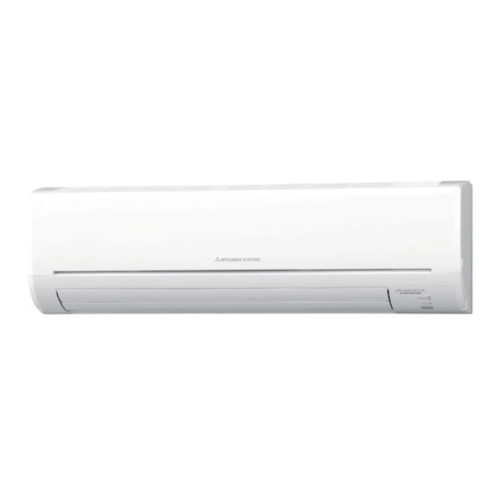
INDOOR UNIT
SERVICE MANUAL
Models
MSZ-GF60VE
MSZ-GF60VE2
MSZ-GF71VE
MSZ-GF71VE2
NOTE:
RoHS compliant products have <G> mark on the spec name plate.
-
E1
ER1
,
-
E1
ER1
,
-
E1
ER1
,
-
E1
ER1
,
CONTENTS
1. TECHNICAL CHANGES ··································· 3
2. PART NAMES AND FUNCTIONS ····················· 4
3. SPECIFICATION ················································ 5
4. NOISE CRITERIA CURVES ······························ 6
5. OUTLINES AND DIMENSIONS ························ 7
6. WIRING DIAGRAM ············································ 8
7. REFRIGERANT SYSTEM DIAGRAM ··············· 9
8. SERVICE FUNCTIONS ··································· 10
9. MICROPROCESSOR CONTROL ··················· 12
10. TROUBLESHOOTING ····································· 19
11. DISASSEMBLY INSTRUCTIONS ···················· 33
PARTS CATALOG (OBB634)
Revision B:
• MSZ-GF60VE2-
,
E1
ER1
GF71VE2-
,
have been added.
E1
ER1
Please void OBH634 REVISED EDITION-A.
No. OBH634
REVISED EDITION-B
Outdoor unit service manual
MUZ-GF·VE Series (OBH635)
MXZ-D·VA Series (OBH626)
MXZ-6C122VA (OBH584)
and MSZ-
Advertisement
Table of Contents

Related Manuals for Mitsubishi Electric MSZ-GF60VE - E1


Summary of Contents for Mitsubishi Electric MSZ-GF60VE - E1
-
Page 1: Table Of Contents
Revision B: • MSZ-GF60VE2- and MSZ- GF71VE2- have been added. Please void OBH634 REVISED EDITION-A. INDOOR UNIT No. OBH634 SERVICE MANUAL REVISED EDITION-B Models MSZ-GF60VE MSZ-GF60VE2 MSZ-GF71VE MSZ-GF71VE2 Outdoor unit service manual MUZ-GF·VE Series (OBH635) MXZ-D·VA Series (OBH626) MXZ-6C122VA (OBH584) CONTENTS 1. - Page 2 Use the specifi ed refrigerant only Never use any refrigerant other than that specified. Doing so may cause a burst, an explosion, or fire when the unit is being used, serviced, or disposed of. Correct refrigerant is specified in the manuals and on the spec labels provided with our products. We will not be held responsible for mechanical failure, system malfunction, unit breakdown or accidents caused by failure to follow the instructions.
-
Page 3: Technical Changes
TECHNICAL CHANGES These models are compatible with the outdoor units with low standby power control. Connecting these models to the MUZ-GF·VE-series outdoor units enables the low standby power control. Refer to the techni- cal guide (OBT17) about the low standby power control. These models may be connected to the MUZ-GF·VE series after once connected to the MXZ series and operated, for exam- ple because of relocation. -
Page 4: Part Names And Functions
PART NAMES AND FUNCTIONS MSZ-GF60VE MSZ-GF60VE2 MSZ-GF71VE MSZ-GF71VE2 Front panel Air fi lter [Nano platinum fi lter (GF60/71VE) / Air purifying fi lter (GF60/71VE2)] Air cleaning fi lter [Electrostatic anti-allergy enzyme fi lter, option (GF60/71VE) / Silver-ionized air purifi er fi lter, option (GF60/71VE2)] Air inlet Air outlet Fan guard... -
Page 5: Specification
SPECIFICATION MSZ-GF60VE MSZ-GF71VE Indoor model MSZ-GF60VE2 MSZ-GF71VE2 Power supply Single phase 230 V, 50 Hz Cooling Power input Heating Cooling 0.43 0.51 Running current Heating 0.53 0.51 Model RC0J56-AF Cooling 0.43 0.51 Current Heating 0.53 0.51 Dimensions W × H × D 1100 ×... -
Page 6: Noise Criteria Curves
Specifications and rated conditions of main electric parts Fuse (F11) T3.15AL250V Horizontal vane motor (MV1) 12 VDC Vertical vane motor (MV2) 12 VDC Varistor (NR11) S10K300E3K1 (ERZV10D471) Terminal block (TB) Relay (X1) NOISE CRITERIA CURVES MSZ-GF60VE MSZ-GF60VE2 MSZ-GF71VE MSZ-GF71VE2 FAN SPEED FUNCTION SPL(dB(A)) LINE FAN SPEED... -
Page 7: Outlines And Dimensions
OUTLINES AND DIMENSIONS Unit: mm MSZ-GF60VE MSZ-GF60VE2 MSZ-GF71VE MSZ-GF71VE2 11×26 Oblong hole 11×20 Oblong hole Installation plate 1100 1090 199.5 199.5 Indoor unit 110.5 49.5 500.5 439.5 Air in Installation plate Wall hole Ø75 Piping ( 70° ) Drain hose Air out MSZ-GF60VE MSZ-GF60VE2 Insulation... -
Page 8: Wiring Diagram
WIRING DIAGRAM MSZ-GF60VE - MSZ-GF71VE - MSZ-GF60VE - MSZ-GF71VE - MSZ-GF60VE2 - MSZ-GF60VE2 - MSZ-GF71VE2 - MSZ-GF71VE2 - OBH634B... -
Page 9: Refrigerant System Diagram
REFRIGERANT SYSTEM DIAGRAM Unit: mm MSZ-GF60VE MSZ-GF60VE2 MSZ-GF71VE MSZ-GF71VE2 Refrigerant pipe ø15.88 (with heat insulator) Indoor coil Indoor thermistor heat RT12 (main) exchanger Flared connection Indoor coil thermistor RT13 (sub) Room temperature thermistor RT11 Flared connection Refrigerant pipe ø6.35 (MSZ-GF60VE) (MSZ-GF60VE2) ø9.52 (MSZ-GF71VE) (MSZ-GF71VE2) -
Page 10: Service Functions
SERVICE FUNCTIONS MSZ-GF60VE MSZ-GF60VE2 MSZ-GF71VE MSZ-GF71VE2 8-1. TIMER SHORT MODE For service, the following set time can be shortened by bridging JPG and JPS on the electronic control P.C. board. (Refer to 10-7.1.) • The set time for the ON/OFF timer can be reduced to 1 second for each minute. •... - Page 11 8-3. AUTO RESTART FUNCTION When the indoor unit is controlled with the remote controller, the operation mode, the set temperature, and the fan speed are memorized by the indoor electronic control P.C. board. “AUTO RESTART FUNCTION” automatically starts operation in the same mode just before the shutoff of the main power. Operation If the main power has been cut, the operation settings remain.
-
Page 12: Microprocessor Control
MICROPROCESSOR CONTROL MSZ-GF60VE MSZ-GF60VE2 MSZ-GF71VE MSZ-GF71VE2 WIRELESS REMOTE CONTROLLER MSZ-GF60VE MSZ-GF71VE Signal transmitting section LONG button WIDE VANE CONTROL button OPERATION SELECT button Operation display section FAN SPEED CONTROL button ECONO COOL button VANE CONTROL button TIME, TIMER set buttons POWERFUL button FORWARD button BACKWARD button... - Page 13 INDOOR UNIT DISPLAY SECTION Operation Indicator lamp The operation indicator at the right side of the indoor unit indicates the operation state. •The following indication applies regardless of shape of the indication. Indication Operation state Room temperature The unit is operating to About 2°C or more away Lighted reach the set temperature...
- Page 14 9-4. AUTO CHANGE OVER ··· AUTO MODE OPERATION Once desired temperature is set, unit operation is switched automatically between COOL and HEAT operation. Mode selection (1) Initial mode When unit starts the operation with AUTO operation from OFF: • If the room temperature is higher than the set temperature, operation starts in COOL mode. •...
- Page 15 (5) STOP (operation OFF) and ON TIMER standby In the following cases, the horizontal vane returns to the closed position. (a) When OPERATE/STOP (ON/OFF) (GF60/71VE) / STOP/OPERATE (OFF/ON) (GF60/71VE2) button is pressed (POWER OFF). (b) When the operation is stopped by the emergency operation. (c) When ON TIMER is ON standby.
- Page 16 (3) Positioning To confirm the standard position, the vane moves until it touches the vane stopper. Then the vane is set to the select- ed angle. (SWING) Confirmation of standard position is performed in the following cases: (a) OPERATE/STOP OPERATE/STOP (ON/OFF) (GF60/71VE) / STOP/OPERATE (OFF/ON) (GF60/71VE2) button is pressed (POWER ON).
- Page 17 9-7. WEEKLY TIMER OPERATION • A maximum of 4 ON or OFF timers can be set for individual days of the week. • A maximum of 28 ON or OFF timers can be set for a week. NOTE: • The simple ON/OFF timer setting is available while the weekly timer is on. In this case, the ON/OFF timer has priority over the weekly timer;...
- Page 18 (5) Press button to turn the weekly timer ON. ( lights.) •When the weekly timer is ON, the day of the week whose timer setting is complete, will light. Press button again to turn the weekly timer OFF. ( goes out.) NOTE: The saved settings will not be cleared when the weekly timer is turned OFF.
-
Page 19: Troubleshooting
TROUBLESHOOTING MSZ-GF60VE MSZ-GF60VE2 MSZ-GF71VE MSZ-GF71VE2 10-1. CAUTIONS ON TROUBLESHOOTING 1. Before troubleshooting, check the following 1) Check the power supply voltage. 2) Check the indoor/outdoor connecting wire for miswiring. 2. Take care of the following during servicing 1) Before servicing the air conditioner, be sure to turn OFF the main unit first with the remote controller, and after confirm- ing the horizontal vane is closed, turn OFF the breaker and/or disconnect the power plug. - Page 20 5. How to install the horizontal vane If horizontal vane is not installed correctly, all of the operation indicator lamps will blink. In this case, install the horizontal vane correctly by following the procedures NOTE: Before installation of the horizontal vane, turn OFF the power supply. Lock Vane Check the upper and the lower vane.
- Page 21 10-2. FAILURE MODE RECALL FUNCTION Outline of the function This air conditioner can memorize the abnormal condition which has occurred once. Even though LED indication listed on the troubleshooting check table (10-4.) disappears, the memorized failure details can be recalled. MSZ-GF60VE MSZ-GF60VE2 1.
- Page 22 2. Indoor unit failure mode table Upper lamp of OP- Abnormal point ERATION INDICA- Condition Remedy (Failure mode) TOR lamp Not lighted Normal — — The room temperature thermistor short or 1-time fl ash every Room temperature Refer to the characteristics of the room temperature open circuit is detected every 8 seconds dur- 0.5-second thermistor...
- Page 23 10-3. INSTRUCTION OF TROUBLESHOOTING Start Indoor unit operates. Indoor unit does Indoor unit oper- OPERATION INDICATOR Outdoor unit does not receive the ates. lamp on the indoor unit is not operate normally. Outdoor unit signal from re- fl ashing ON and OFF. mote controller.
- Page 24 10-4. TROUBLESHOOTING CHECK TABLE Before taking measures, make sure that the symptom reappears for accurate troubleshooting. When the indoor unit has started operation and detected an abnormality of the following condition (the first detection after the power ON), the indoor fan motor turns OFF and OPERATION INDICATOR lamp flashes. OPERATION INDICATOR Lighted Blinking...
- Page 25 OPERATION INDICATOR Abnormal Operation indicator lamp Symptom Condition Remedy point All lamps fl ash at the same time. Attachment Indoor unit and • Refer to 10-6. "Check of 0.5-second ON The electricity is not conducted to the inter- of the hori- outdoor unit do installation of the horizontal lock switch (Fan) of the horizontal vane.
- Page 26 10-6. TROUBLESHOOTING FLOW A Check of indoor fan motor The indoor fan motor error has occurred, and the indoor fan does not operate. Turn OFF the power supply. Pay enough attention to the high voltage on the fan motor connector CN211. Turn ON the power supply, wait 5 seconds or more, and then press EMERGENCY OPERATION switch.
- Page 27 B Check of remote controller and indoor electronic control P.C. board Check if the remote controller is exclusive for this air conditioner. Press OPERATE/STOP (ON/OFF) (GF60/71VE) / STOP/OPERATE (OFF/ON) (GF60/71VE2) button on the remote controller. 1 Look at the image of the signal transmitting section of Is LCD display on the remote controller the remote controller through the monitor of a digital Replace the batteries.
- Page 28 C Check of indoor P.C. board and indoor fan motor Turn OFF the power supply. Remove indoor fan motor connector CN211 and vane Short/open circuit: Measure the resistance between CN211 Replace the indoor fan motor. motor connector CN151 and CN152 from the indoor of the indoor fan motor connector.
- Page 29 D How to check miswiring and serial signal error Turn the power supply OFF. NOTE: Refer to the outdoor unit service manual. Is there rated voltage in the power supply? Check the power supply. Check for incorrect indoor-outdoor connecting wiring. Was the indoor unit ever connected to the Multi •...
- Page 30 E Check of installation of the horizontal vane Turn OFF the power supply. Re-lock the stopper of the hori- Is the stopper of the horizontal vane Turn ON the zontal vane to the indoor unit. locked to the indoor unit correctly? power supply.
- Page 31 F Electromagnetic noise enters into TV sets or radios Is the unit earthed? Earth the unit. Is the distance between the antennas Extend the distance between the antennas and and the indoor unit within 3 m, or is the the indoor unit, and/or the antennas and the distance between the antennas and the outdoor unit.
- Page 32 10-7. TEST POINT DIAGRAM AND VOLTAGE 1. Indoor electronic control P.C. board, Indoor terminal P.C. board, Power monitor receiver SW P.C. board MSZ-GF60VE MSZ-GF60VE2 MSZ-GF71VE MSZ-GF71VE2 Indoor terminal P.C. board Indoor electronic control P.C. board To disable "Auto restart func- tion"...
-
Page 33: Disassembly Instructions
DISASSEMBLY INSTRUCTIONS <"Terminal with locking mechanism" Detaching points> The terminal which has the locking mechanism can be detached as shown below. There are 2 types (Refer to (1) and (2)) of the terminal with locking mechanism. The terminal without locking mechanism can be detached by pulling it out. Check the shape of the terminal before detaching. - Page 34 OPERATING PROCEDURE PHOTOS 2. Removing the indoor electronic control P.C. Photo 2 Electrical box board, the power monitor receiver SW P.C. board and the indoor terminal P.C. board (1) Remove the panel (Refer to 1.) and the right corner box. Screw of the (2) Remove the screw of the V.A.
- Page 35 OPERATING PROCEDURE PHOTOS 4. Removing the nozzle assembly Photo 4 (1) Remove the panel (Refer to 1.) and the corner box. (2) Remove the V.A. clamp, and then the indoor/outdoor connecting wire. (Photo 2) (3) Remove the electrical cover. (Photo 2) (4) Disconnect the following connectors on the electronic control P.C.
- Page 36 OPERATING PROCEDURE PHOTOS 7. Removing the water cut, the indoor fan motor, Photo 8 the indoor coil thermistor, and the line flow fan (1) Remove the panel (Refer to 1.) and the corner box. (2) Remove the power monitor receiver holder, the elec- trical box and the nozzle assembly.
- Page 37 Fixing the indoor coil thermistor There are 2 forms of parts for fixing the indoor coil thermistor. When fixing the indoor coil thermistor to the clip-shape/holder-shape part, the Clip shape Holder shape lead wire should point down. About the same length Position and procedure for mounting the clip-shape part 1.
- Page 38 HEAD OFFICE: TOKYO BLDG., 2-7-3, MARUNOUCHI, CHIYODA-KU, TOKYO 100-8310, JAPAN © Copyright 2013 MITSUBISHI ELECTRIC CORPORATION Distributed in Dec. 2015. No. OBH634 REVISED EDITION-B Distributed in Dec. 2013. No. OBH634 REVISED EDITION-A Distributed in Mar. 2013. No. OBH634 New publication, effective Dec. 2015 Made in Japan Specifications are subject to change without notice.