Table of Contents
Advertisement
I/O Module Type Building Block
User's Manual
QX10
QX10-TS
QX28
QX40
QX40-S1
QX40-TS
QX40H
QX41
QX41-S1
QX41-S2
QX42
QX42-S1
QX50
QX70
QX70H
QX71
QX72
QX80
QX80-TS
QX80H
QX81
QX81-S2
QX82
QX82-S1
QX90H
QY10
QY10-TS
QY18A
QY22
QY40P
QY40P-TS
QY41H
QY41P
QY42P
QY50
QY68A
QY70
QY71
QY80
QY80-TS
QY81P
QY82P
QH42P
QX41Y41P
QX48Y57
QI60
Advertisement
Table of Contents
Troubleshooting

Related Manuals for Mitsubishi Electric QX10-TS


Summary of Contents for Mitsubishi Electric QX10-TS
- Page 1 I/O Module Type Building Block User's Manual QX10 QY10 QX10-TS QY10-TS QX28 QY18A QX40 QY22 QX40-S1 QY40P QX40-TS QY40P-TS QX40H QY41H QX41 QY41P QX41-S1 QY42P QX41-S2 QY50 QX42 QY68A QX42-S1 QY70 QX50 QY71 QX70 QY80 QX70H QY80-TS QX71 QY81P QX72...
-
Page 3: Safety Precautions
SAFETY PRECAUTIONS (Read these precautions before using this product.) Before using this product, please read this manual and the relevant manuals carefully and pay full attention to safety to handle the product correctly. The precautions given in this manual are concerned with this product only. For the safety precautions of the programmable controller system, refer to the user’s manual for the CPU module used. - Page 4 [Design Precautions] WARNING • In an output module, when a load current exceeding the rated current or an overcurrent caused by a load short-circuit flows for a long time, it may cause smoke and fire. To prevent this, configure an external safety circuit, such as a fuse. •...
- Page 5 [Installation Precautions] CAUTION • Use the programmable controller in an environment that meets the general specifications in the user’s manual for the CPU module used. Failure to do so may result in electric shock, fire, malfunction, or damage to or deterioration of the product.
- Page 6 Do not remove the film during wiring. Remove it for heat dissipation before system operation. • Mitsubishi Electric programmable controllers must be installed in control panels. Connect the main power supply to the power supply module in the control panel through a relay terminal block.
- Page 7 [Startup and Maintenance Precautions] WARNING • Do not touch any terminal while power is on. Doing so will cause electric shock. • Correctly connect the battery connector. Do not charge, disassemble, heat, short-circuit, or solder the battery, or throw it into the fire. Doing so will cause the battery to produce heat, explode, or ignite, resulting in injury and fire.
- Page 8 [Startup and Maintenance Precautions] CAUTION • Before performing online operations (especially, program modification, forced output, and operating status change) for the running CPU module from the peripheral device connected, read relevant manuals carefully and ensure the safety. Improper operation may damage machines or cause accidents. •...
-
Page 9: Conditions Of Use For The Product
• CONDITIONS OF USE FOR THE PRODUCT • (1) Mitsubishi programmable controller ("the PRODUCT") shall be used in conditions; i) where any problem, fault or failure occurring in the PRODUCT, if any, shall not lead to any major or serious accident; and ii) where the backup and fail-safe function are systematically or automatically provided outside of the PRODUCT for the case of any problem, fault or failure occurring in the PRODUCT. -
Page 10: Revisions
REVISIONS The manual number is given on the bottom left of the back cover. Print Date Manual Number Revision Dec., 1999 SH(NA)-080042-A First edition Feb., 2000 SH(NA)-080042-B Addition model QH42P, QX48Y57, QX70, QX71, QX72, QY18A Addition Chapter 4 Partial correction Section 1.2, Chapter 5, 8.1 Chapters 4 to 8 (changed into Chapters 5 to 9) Apr., 2000... - Page 11 Addition Section 4.2 Jun., 2008 SH(NA)-080042-S Addition model QX10-TS, QX40-TS, QX80-TS, QY10-TS, QY40P-TS, QY80-TS Partial correction Section 1.2, 2.3 to 2.19, 3.3 to 3.15, 9.2, Chapter 10 Addition Section 2.2, 2.6, 2.16, 3.2, 3.6, 3.14, 9.1, 9.3 A - 9...
- Page 12 Print Date Manual Number Revision Oct., 2008 SH(NA)-080042-T Addition model QX40-H, QX70-H, QX80-H, QX90-H Partial correction Section 1.2.5, 1.3.1, 2.8 to 2.23, 9.2, Chapter 10 Addition Section 2.7, 2.14, 2.19, 2.23 Apr., 2009 SH(NA)-080042-U Addition model QX41-S2, QX81-S2 Partial correction Section 2.7, 2.11 to 2.25, 5.1, 8.1 Addition Section 2.10, 2.22...
- Page 13 This manual confers no industrial property rights or any rights of any other kind, nor does it confer any patent licenses. Mitsubishi Electric Corporation cannot be held responsible for any problems involving industrial property rights which may occur as a result of using the contents noted in this manual.
-
Page 14: Table Of Contents
INTRODUCTION Thank you for purchasing the Mitsubishi Electric MELSEC-Q series programmable controllers. Before using this product, please read this manual carefully and develop familiarity with the functions and performance of the MELSEC-Q series programmable controller to handle the product correctly. - Page 15 2.20 QX80H DC High-speed Input Module (Negative Common Type) ............. 2-26 2.21 QX81 DC Input Module (Negative Common Type) ................2-28 2.22 QX81-S2 DC Input Module (Negative Common Type) ............... 2-29 2.23 QX82 DC Input Module (Negative Common Type) ................2-30 2.24 QX82-S1 DC Input Module (Negative Common Type) ...............
- Page 16 8.2.5 A6TBY36-E ............................8- 6 8.2.6 A6TBX54-E ............................8- 6 8.2.7 A6TBY54-E ............................8- 7 8.2.8 A6TBX70-E ............................8- 7 9. SPRING CLAMP TERMINAL BLOCK 9- 1 to 9- 9 9.1 Spring Clamp Terminal Block I/O Module ..................9- 1 9.2 Spring Clamp Terminal Block (Q6TE-18S, Q6TE-18SN) ..............
-
Page 17: About Manuals
COMPLIANCE WITH EMC AND LOW VOLTAGE DIRECTIVES (1) Method of ensuring compliance To ensure that Mitsubishi Electric programmable controllers maintain EMC and Low Voltage Directives when incorporated into other machinery or equipment, certain measures may be necessary. Please refer to one of the following manuals. - Page 18 MEMO A - 16 A - 16...
-
Page 19: General Specifications And Precautions For Use
GENERAL SPECIFICATIONS AND PRECAUTIONS FOR USE MELSEC-Q 1. GENERAL SPECIFICATIONS AND PRECAUTIONS FOR USE This chapter describes the general specifications and precautions for use of the I/O modules. 1.1 General Specifications Refer to the following manual for the general specifications of the I/O modules. •... - Page 20 GENERAL SPECIFICATIONS AND PRECAUTIONS FOR USE MELSEC-Q (3) Precautions for using the DC input module (a) Measure against back EMF When an inductive load is connected, connect a diode to the load in parallel. Use a diode that meets the following conditions. •...
-
Page 21: Output Module
GENERAL SPECIFICATIONS AND PRECAUTIONS FOR USE MELSEC-Q (c) If the small number of value of input response time is set, the modules tend to have impact of noise. Ensure that the modules do not have impact of noise. For details of the measure against noise, refer to the QCPU User’s Manual (Hardware Design, Maintenance and Inspection). - Page 22 GENERAL SPECIFICATIONS AND PRECAUTIONS FOR USE MELSEC-Q (5) Fuses installed to external terminals It is recommended to install fuses to each external terminal. These fuses works to prevent the external devices and the module from being burned when a short circuit occurs in the load circuit of the QY22 or QY68A.
- Page 23 GENERAL SPECIFICATIONS AND PRECAUTIONS FOR USE MELSEC-Q (b) Measure against back EMF When an inductive load is connected, connect a diode to the load in parallel. Use a diode that meets the following conditions. • Reverse breakdown voltage is 10 times as high as the circuit voltage or more.
- Page 24 GENERAL SPECIFICATIONS AND PRECAUTIONS FOR USE MELSEC-Q (7) Precautions for using the contact output module When using the contact output module, consider the following. • Relay life (contact switching life) • Effects to relay life due to connected load • Measures against back EMF (a) Relay life Applicable module: QY10, QY10-TS, QY18A The relay life depends on the operating environment.
- Page 25 GENERAL SPECIFICATIONS AND PRECAUTIONS FOR USE MELSEC-Q Operating environment Switching life Rated switching voltage/current load 100 thousand times 200VAC 1.5A, 240VAC 1A (COS =0.7) 100 thousand times 200VAC 0.4A, 240VAC 0.3A (COS =0.7) 300 thousand times 200VAC 1A, 240VAC 0.5A (COS =0.35) 100 thousand times 200VAC 0.3A, 240VAC 0.15A (COS...
- Page 26 GENERAL SPECIFICATIONS AND PRECAUTIONS FOR USE MELSEC-Q (b) Measures against inrush current The actual relay life may be significantly shortened compared to the one shown in (7)(a), depending on the type of a load connected and the characteristics of inrush current. Also, the inrush current may cause contact welding.
- Page 27 GENERAL SPECIFICATIONS AND PRECAUTIONS FOR USE MELSEC-Q Inrush Inrush Load type Signal waveform diagram current(i)/rated Signal waveform diagram current(i)/rated current (io) current (io) Capacitive Approx. 20 to ― ― load 40 times *2: When the wiring of the circuit is long, take care of the wire capacity. 1 - 9 1 - 9...
- Page 28 GENERAL SPECIFICATIONS AND PRECAUTIONS FOR USE MELSEC-Q (c) Measures against back EMF Configure a contact protection circuit for extending the contact life, preventing noise when the contact is cut off, and suppressing the generation of carbide and nitric acid due to arc discharge. An Incorrect contact protection circuit may cause contact welding.
- Page 29 GENERAL SPECIFICATIONS AND PRECAUTIONS FOR USE MELSEC-Q Circuit example Method for selecting elements Remarks Varistor method Select a cut voltage (Vc) for The recovery time delays the varistor to meet the slightly. following condition. Multiply the value by root two for use of AC power.
- Page 30 GENERAL SPECIFICATIONS AND PRECAUTIONS FOR USE MELSEC-Q (8) Precautions for using the triac output module Because of characteristics of a triac, a sudden change of voltage or current may cause unstable operations of a triac used for the triac output module. Whether the voltage or current change causes a problem differs depending on an individual part (each triac), thus check the following when using the triac output module.
- Page 31 GENERAL SPECIFICATIONS AND PRECAUTIONS FOR USE MELSEC-Q Circuit example Method for selecting elements Remarks Capacitor + Refer to the following for If a load is a relay or Resistor constants of the capacitor and solenoid, the recovery time method (CR resistor.
-
Page 32: I/O Combined Module
GENERAL SPECIFICATIONS AND PRECAUTIONS FOR USE MELSEC-Q 1.2.3 I/O combined module (1) I/O numbers of I/O combined modules There are two types of I/O combined modules: • Module using same I/O numbers for input and output Since same number is used for input and output, the I/O numbers to be used can be saved. -
Page 33: I/O Module With Protection Function
GENERAL SPECIFICATIONS AND PRECAUTIONS FOR USE MELSEC-Q 1.2.4 I/O module with protection function The overload protection function and overheat protection function of the following modules are explained below. (1) QY40P, QY41P, QY42P, QX41Y41P, QH42P Function Description • If an overcurrent due to overload keeps flowing, heat is generated and the overheat protection function is activated. -
Page 34: Interrupt Module
GENERAL SPECIFICATIONS AND PRECAUTIONS FOR USE MELSEC-Q 1.2.5 Interrupt module (1) If setting the response time during the interrupt input operation of QI60 or QX40H, QX70H, QX80H, and QX90H, use the module whose contents are shown below. The response time cannot be set with other contents (fixed at 0.2ms.). Product Description CPU module... -
Page 35: Various Settings For I/O Module
GENERAL SPECIFICATIONS AND PRECAUTIONS FOR USE MELSEC-Q 1.3 Various Settings for I/O Module Various settings for the I/O module can be made with GX Developer. This section describes how to make the settings with GX Developer. 1.3.1 Setting of I/O response time Set the I/O response time on the I/O assignment tab of PLC Parameter. - Page 36 GENERAL SPECIFICATIONS AND PRECAUTIONS FOR USE MELSEC-Q (2) For input module/QX40-S1, QX41-S1, QX42-S1, QX82-S1 and interrupt module/QI60 Select "Hi. input" or "Interrupt" in "Type" combo box on the I/O assignment tab of PLC parameter. Then, click the "Detailed setting" button, and then select the input response time in "I/O response time"...
- Page 37 GENERAL SPECIFICATIONS AND PRECAUTIONS FOR USE MELSEC-Q (3) For high-speed input module/QX40H, QX70H, QX80H, QX90H Select "Hi.input" or "Interrupt", which is the same module type as the one selected with the high-speed input module switch, in "Type" combo box on the I/O assignment tab of PLC parameter.
-
Page 38: Setting Of Error-Time Output Mode
GENERAL SPECIFICATIONS AND PRECAUTIONS FOR USE MELSEC-Q 1.3.2 Setting of error-time output mode Set the error-time output mode on the I/O assignment tab of PLC parameter in GX Developer. Select "Output" or "I/O mix" in the "Type" combo box on the I/O assignment tab of PLC parameter. -
Page 39: Switch Setting Of Interrupt Module
GENERAL SPECIFICATIONS AND PRECAUTIONS FOR USE MELSEC-Q 1.3.3 Switch setting of interrupt module Perform the switch setting on the I/O assignment tab of PLC parameter when operating the interrupt input for QI60, QX40H, QX70H, QX80H, or QX90H. Select "Interrupt" in the "Type" combo box on the I/O assignment tab of PLC parameter. - Page 40 GENERAL SPECIFICATIONS AND PRECAUTIONS FOR USE MELSEC-Q MEMO 1 - 22 1 - 22...
-
Page 41: Input Module Specifications
2 INPUT MODULE SPECIFICATIONS MELSEC-Q 2. INPUT MODULE SPECIFICATIONS 2.1 QX10 AC Input Module Type AC input module Specifications QX10 Appearance Number of input points 16 points Isolation method Photocoupler Rated input voltage, frequency 100-120VAC (+10/-15%) 50/60Hz (±3Hz) QX10 0 1 2 3 4 5 6 7 Input voltage distortion Within 5% (Refer to section 1.2) 8 9 A B C D E F... -
Page 42: Qx10-Ts Ac Input Module
2 INPUT MODULE SPECIFICATIONS MELSEC-Q 2.2 QX10-TS AC Input Module This module is a spring clamp terminal block type and an input module that has indicators for checking the insertion state of wire. Type AC input module Specifications QX10-TS Appearance... -
Page 43: Qx28 Ac Input Module
2 INPUT MODULE SPECIFICATIONS MELSEC-Q 2.3 QX28 AC Input Module Type AC input module Specifications QX28 Appearance Number of input points 8 points Isolation method Photocoupler Rated input voltage, frequency 100-240VAC (+10/-15%) 50/60Hz (±3Hz) Input voltage distortion Within 5% (Refer to section 1.2) QX28 0 1 2 3 4 5 6 7 Approx. -
Page 44: Qx40 Dc Input Module (Positive Common Type)
2 INPUT MODULE SPECIFICATIONS MELSEC-Q 2.4 QX40 DC Input Module (Positive Common Type) Type DC input module (Positive common type) Specifications QX40 Appearance Number of input points 16 points Isolation method Photocoupler Rated input voltage 24VDC (+20/-15%, ripple ratio within 5%) Rated input current Approx. -
Page 45: Qx40-S1 Dc Input Module (Positive Common Type)
2 INPUT MODULE SPECIFICATIONS MELSEC-Q 2.5 QX40-S1 DC Input Module (Positive Common Type) Type DC input module (Positive common type) Specifications QX40-S1 Appearance Number of input points 16 points Isolation method Photocoupler Rated input voltage 24VDC (+20/-15%, ripple ratio within 5%) Rated input current Approx. -
Page 46: Qx40-Ts Dc Input Module (Positive Common Type)
2 INPUT MODULE SPECIFICATIONS MELSEC-Q 2.6 QX40-TS DC Input Module (Positive Common Type) This module is a spring clamp terminal block type and an input module that has indicators for checking the insertion state of wire. Type DC input module (Positive common type) Specifications QX40-TS Appearance... -
Page 47: Qx40H Dc High-Speed Input Module (Positive Common Type)
2 INPUT MODULE SPECIFICATIONS MELSEC-Q 2.7 QX40H DC High-Speed Input Module (Positive Common Type) DC high-speed input module (Positive common type) Type Specifications QX40H Appearance Number of input points 16 points Isolation method Photocoupler Rated input voltage 24VDC (+20/-15%, ripple ratio within 5%) Rated input current Approx. - Page 48 2 INPUT MODULE SPECIFICATIONS MELSEC-Q Terminal block No. Signal name Derating chart 26.4VDC 28.8VDC ON ratio/ common 50 55 Ambient temperature External connection COM1 TB10 TB11 TB12 TB13 TB14 TB15 TB16 TB17 TB18 COM2 2 - 8 2 - 8...
-
Page 49: Qx41 Dc Input Module (Positive Common Type)
2 INPUT MODULE SPECIFICATIONS MELSEC-Q 2.8 QX41 DC Input Module (Positive Common Type) Type DC input module (Positive common type) Specifications QX41 Appearance Number of input points 32 points Isolation method Photocoupler Rated input voltage 24VDC (+20/-15%, ripple ratio within 5%) Rated input current Approx. -
Page 50: Qx41-S1 Dc Input Module (Positive Common Type)
2 INPUT MODULE SPECIFICATIONS MELSEC-Q 2.9 QX41-S1 DC Input Module (Positive Common Type) Type DC input module (Positive common type) Specifications QX41-S1 Appearance Number of input points 32 points Isolation method Photocoupler Rated input voltage 24VDC (+20/-15%, ripple ratio within 5%) Rated input current Approx. - Page 51 2 INPUT MODULE SPECIFICATIONS MELSEC-Q Signal Signal Derating chart Pin-Outs 28.8VDC ratio 50 55 Ambient temperature External connection B04 Vacant A04 Vacant Module front view B03 Vacant A03 Vacant A02 Vacant A01 Vacant 2 - 11 2 - 11...
-
Page 52: Qx41-S2 Dc Input Module (Positive Common Type)
2 INPUT MODULE SPECIFICATIONS MELSEC-Q 2.10 QX41-S2 DC Input Module (Positive Common Type) Type DC input module (Positive common type) Specifications QX41-S2 Appearance Number of input points 32 points Isolation method Photocoupler Rated input voltage 24VDC (+20/-15%, ripple ratio within 5%) Rated input current Approx. -
Page 53: Qx42 Dc Input Module (Positive Common Type)
2 INPUT MODULE SPECIFICATIONS MELSEC-Q 2.11 QX42 DC Input Module (Positive Common Type) Type DC input module (Positive common type) Specifications QX42 Appearance Number of input points 64 points Isolation method Photocoupler Rated input voltage 24VDC (+20/-15%, ripple ratio within 5%) QX42 0 1 2 3 4 5 6 7 Rated input current... - Page 54 2 INPUT MODULE SPECIFICATIONS MELSEC-Q Signal Signal Signal Signal Derating chart Pin-Outs 1B20 1A20 2B20 2A20 1B19 1A19 2B19 2A19 1B18 1A18 2B18 2A18 1B17 1A17 2B17 2A17 ON ratio/ 24VDC common 1B16 1A16 2B16 2A16 26.4VDC 1B15 1A15 2B15 2A15 28.8VDC 1B14...
-
Page 55: Qx42-S1 Dc Input Module (Positive Common Type)
2 INPUT MODULE SPECIFICATIONS MELSEC-Q 2.12 QX42-S1 DC Input Module (Positive Common Type) Type DC input module (Positive common type) Specifications QX42-S1 Appearance Number of input points 64 points Isolation method Photocoupler Rated input voltage 24VDC (+20/-15%, ripple ratio within 5%) Rated input current Approx. - Page 56 2 INPUT MODULE SPECIFICATIONS MELSEC-Q Signal Signal Signal Signal Derating chart Pin-Outs 1B20 1A20 2B20 2A20 1B19 1A19 2B19 2A19 1B18 1A18 2B18 2A18 1B17 1A17 2B17 2A17 ON ratio/ 24VDC common 1B16 1A16 2B16 2A16 26.4VDC 1B15 1A15 2B15 2A15 28.8VDC 1B14...
-
Page 57: Qx50 Dc (Positive Common/Negative Common Shared Type)/ Ac Input Module
2 INPUT MODULE SPECIFICATIONS MELSEC-Q 2.13 QX50 DC (Positive Common/Negative Common Shared Type)/ AC Input Module DC (positive/negative shared common type)/ AC input module Type QX50 Appearance Specifications DC Input AC Input Number of input points 16 points Isolation method Photocoupler QX50 48VDC... -
Page 58: Qx70 Dc Input Module (Positive Common/Negative Common Shared Type)
2 INPUT MODULE SPECIFICATIONS MELSEC-Q 2.14 QX70 DC Input Module (Positive Common/Negative Common Shared Type) Type DC input module (Positive/negative shared common type) Specifications QX70 Appearance Number of input points 16 points Isolation method Photocoupler 5VDC 12VDC Rated input voltage (+20/-10%, ripple ratio within 5%) (+20/-15%, ripple ratio within 5%) QX70... -
Page 59: Qx70H Dc High-Speed Input Module (Positive Common Type)
2 INPUT MODULE SPECIFICATIONS MELSEC-Q 2.15 QX70H DC High-speed Input Module (Positive Common Type) Type DC high-speed input module (Positive common type) Specifications QX70H Appearance Number of input points 16 points Isolation method Photocoupler Rated input voltage 5VDC (+20/-15%, ripple ratio within 5%) Rated input current Approx. - Page 60 2 INPUT MODULE SPECIFICATIONS MELSEC-Q External connection Terminal block No. Signal name COM1 TB10 TB11 TB12 TB13 TB14 TB15 TB16 TB17 TB18 COM2 2 - 20 2 - 20...
-
Page 61: Qx71 Dc Input Module (Positive/Negative Shared Common Type)
2 INPUT MODULE SPECIFICATIONS MELSEC-Q 2.16 QX71 DC Input Module (Positive/Negative Shared Common Type) Type DC input module (Positive/negative shared common type) Specifications QX71 Appearance Number of input points 32 points Isolation method Photocoupler 5VDC 12VDC Rated input voltage (+20/-10%, ripple ratio within 5%) (+20/-15%, ripple ratio within 5%) QX71 Rated input current... -
Page 62: Qx72 Dc Input Module (Positive/Negative Shared Common Type)
2 INPUT MODULE SPECIFICATIONS MELSEC-Q 2.17 QX72 DC Input Module (Positive/Negative Shared Common Type) Type DC input module (Positive/negative shared common type) Specifications QX72 Appearance Number of input points 64 points Isolation method Photocoupler 5VDC 12VDC Rated input voltage QX72 (+20/-10%, ripple ratio within 5%) (+20/-15%, ripple ratio within 5%) 0 1 2 3 4 5 6 7... - Page 63 2 INPUT MODULE SPECIFICATIONS MELSEC-Q Signal Signal Signal Signal External connection Pin-Outs 1B20 1A20 2B20 2A20 1B19 1A19 2B19 2A19 1B18 1A18 2B18 2A18 1B17 1A17 2B17 2A17 1B16 1A16 2B16 2A16 1B15 1A15 2B15 2A15 1B14 1A14 2B14 2A14 1B13 1A13 2B13...
-
Page 64: Qx80 Dc Input Module (Negative Common Type)
2 INPUT MODULE SPECIFICATIONS MELSEC-Q 2.18 QX80 DC Input Module (Negative Common Type) Type DC input module (Negative common type) Specifications QX80 Appearance Number of input points 16 points Isolation method Photocoupler Rated input voltage 24VDC (+20/-15%, ripple ratio within 5%) Rated input current Approx. -
Page 65: Qx80-Ts Dc Input Module (Negative Common Type)
2 INPUT MODULE SPECIFICATIONS MELSEC-Q 2.19 QX80-TS DC Input Module (Negative Common Type) This module is a spring clamp terminal block type and an input module that has indicators for checking the insertion state of wire. Type DC input module (Negative common type) Specifications QX80-TS Appearance... -
Page 66: Qx80H Dc High-Speed Input Module (Negative Common Type)
2 INPUT MODULE SPECIFICATIONS MELSEC-Q 2.20 QX80H DC High-speed Input Module (Negative Common Type) DC high-speed input module (Negative common type) Type Specifications QX80H Appearance Number of input points 16 points Isolation method Photocoupler Rated input voltage 24VDC (+20/-15%, ripple ratio within 5%) Rated input current Approx. - Page 67 2 INPUT MODULE SPECIFICATIONS MELSEC-Q Terminal block No. Signal name Derating chart 26.4VDC 28.8VDC ON ratio/ common 50 55 Ambient temperature External connection COM1 TB10 TB11 TB12 TB13 TB14 TB15 TB16 TB17 TB18 COM2 2 - 27 2 - 27...
-
Page 68: Qx81 Dc Input Module (Negative Common Type)
2 INPUT MODULE SPECIFICATIONS MELSEC-Q 2.21 QX81 DC Input Module (Negative Common Type) Type DC input module (Negative common type) Specifications QX81 Appearance Number of input points 32 points Isolation method Photocoupler Rated input voltage 24VDC (+20/-15%, ripple ratio within 5%) Rated input current Approx. -
Page 69: Qx81-S2 Dc Input Module (Negative Common Type)
2 INPUT MODULE SPECIFICATIONS MELSEC-Q 2.22 QX81-S2 DC Input Module (Negative Common Type) Type DC input module (Negative common type) Specifications QX81-S2 Appearance Number of input points 32 points Isolation method Photocoupler Rated input voltage 24VDC (+20/-15%, ripple ratio within 5%) Rated input current Approx. -
Page 70: Qx82 Dc Input Module (Negative Common Type)
2 INPUT MODULE SPECIFICATIONS MELSEC-Q 2.23 QX82 DC Input Module (Negative Common Type) Type DC input module (Negative common type) Specifications QX82 Appearance Number of input points 64 points Isolation method Photocoupler Rated input voltage 24VDC (+20/-15%, ripple ratio within 5%) QX82 0 1 2 3 4 5 6 7 Rated input current... - Page 71 2 INPUT MODULE SPECIFICATIONS MELSEC-Q Signal Signal Signal Signal Derating chart Pin-Outs 1B20 1A20 2B20 2A20 1B19 1A19 2B19 2A19 1B18 1A18 2B18 2A18 1B17 1A17 2B17 2A17 ON ratio/ 24VDC common 1B16 1A16 2B16 2A16 26.4VDC 1B15 1A15 2B15 2A15 28.8VDC 1B14...
-
Page 72: Qx82-S1 Dc Input Module (Negative Common Type)
2 INPUT MODULE SPECIFICATIONS MELSEC-Q 2.24 QX82-S1 DC Input Module (Negative Common Type) Type DC input module (Negative common type) Specifications QX82-S1 Appearance Number of input points 64 points Isolation method Photocoupler Rated input voltage 24VDC (+20/-15%, ripple ratio within 5%) Rated input current Approx. - Page 73 2 INPUT MODULE SPECIFICATIONS MELSEC-Q Signal Signal Signal Signal Derating chart Pin-Outs 1B20 1A20 2B20 2A20 1B19 1A19 2B19 2A19 1B18 1A18 2B18 2A18 1B17 1A17 2B17 2A17 ON ratio/ 24VDC common 1B16 1A16 2B16 2A16 26.4VDC 1B15 1A15 2B15 2A15 28.8VDC 1B14...
-
Page 74: Qx90H Dc High-Speed Input Module (Negative Common Type)
2 INPUT MODULE SPECIFICATIONS MELSEC-Q 2.25 QX90H DC High-speed Input Module (Negative Common Type) DC high-speed input module (Negative common type) Type Specifications QX90H Appearance Number of input points 16 points Isolation method Photocoupler Rated input voltage 5VDC (+20/-15%, ripple ratio within 5%) Rated input current Approx. - Page 75 2 INPUT MODULE SPECIFICATIONS MELSEC-Q External connection Terminal block No. Signal name COM1 TB10 TB11 TB12 TB13 TB14 TB15 TB16 TB17 TB18 COM2 2 - 35 2 - 35...
- Page 76 2 INPUT MODULE SPECIFICATIONS MELSEC-Q MEMO 2 - 36 2 - 36...
-
Page 77: Output Module Specifications
3 OUTPUT MODULE SPECIFICATIONS MELSEC-Q 3. OUTPUT MODULE SPECIFICATIONS 3.1 QY10 Contact Output Module Type Contact output module Specifications QY10 Appearance Number of output points 16 points Isolation method Relay 24VDC 2A (resistive load) Rated switching voltage, /point, 8A/common current 240VAC 2A (cos Minimum switching load 5VDC 1mA... -
Page 78: Qy10-Ts Contact Output Module
3 OUTPUT MODULE SPECIFICATIONS MELSEC-Q 3.2 QY10-TS Contact Output Module This module is a spring clamp terminal block type and an output module that has indicators for checking the insertion state of wire. Type Contact output module Specifications QY10-TS Appearance Number of output points 16 points Isolation method... -
Page 79: Qy18A Contact Output Module (All Points Independent)
3 OUTPUT MODULE SPECIFICATIONS MELSEC-Q 3.3 QY18A Contact Output Module (All Points Independent) Type Contact output module (All points independent) Specifications QY18A Appearance Number of output points 8 points Isolation method Relay isolation 24VDC 2A (resistive load) Rated switching /point, 8A/unit voltage/current 240VAC 2A (cos Minimum switching load... -
Page 80: Qy22 Triac Output Module
3 OUTPUT MODULE SPECIFICATIONS MELSEC-Q 3.4 QY22 TRIAC Output Module Type TRIAC output module Specifications QY22 Appearance Number of output points 16 points Isolation method Photocoupler Rated load voltage 100 to 240VAC 50/60Hz Load voltage distortion rate Within 5% Maximum load voltage 264VAC Maximum load current 0.6A/point, 4.8A/common... - Page 81 3 OUTPUT MODULE SPECIFICATIONS MELSEC-Q POINT Do not touch the module during turning on electricity and immediately after power supply interception. There is fear of a burn. 3 - 5 3 - 5...
-
Page 82: Qy40P Transistor Output Module (Sink Type)
3 OUTPUT MODULE SPECIFICATIONS MELSEC-Q 3.5 QY40P Transistor Output Module (Sink Type) Type Transistor output module (Sink type) Specifications QY40P Appearance Number of output points 16 points Isolation method Photocoupler Rated load voltage 12-24VDC (+20/-15%) Maximum load current 0.1A/point, 1.6A/common Maximum inrush current 0.7A, 10ms or less Leakage current at OFF... -
Page 83: Qy40P-Ts Transistor Output Module (Sink Type)
3 OUTPUT MODULE SPECIFICATIONS MELSEC-Q 3.6 QY40P-TS Transistor Output Module (Sink Type) This module is a spring clamp terminal block type and an output module that has indicators for checking the insertion state of wire. Type Transistor output module (Sink type) Specifications QY40P-TS Appearance... -
Page 84: Qy41H Transistor High-Speed Output Module (Sink Type)
3 OUTPUT MODULE SPECIFICATIONS MELSEC-Q 3.7 QY41H Transistor High-speed Output Module (Sink Type) Type Transistor high-speed output module (Sink type) Specifications QY41H Appearance Number of output points 32 points Isolation method Photocoupler Rated load voltage 5-24VDC (+20/-15%) Maximum load current 0.2A/point, 2A/common Maximum inrush current 0.7A, 10ms or less... -
Page 85: Qy41P Transistor Output Module (Sink Type)
3 OUTPUT MODULE SPECIFICATIONS MELSEC-Q 3.8 QY41P Transistor Output Module (Sink Type) Type Transistor output module (Sink type) Specifications QY41P Appearance Number of output points 32 points Isolation method Photocoupler Rated load voltage 12-24VDC (+20/-15%) Maximum load current 0.1A/point, 2A/common Maximum inrush current 0.7A, 10ms or less QY41P... -
Page 86: Qy42P Transistor Output Module (Sink Type)
3 OUTPUT MODULE SPECIFICATIONS MELSEC-Q 3.9 QY42P Transistor Output Module (Sink Type) Type Transistor output module (Sink type) Specifications QY42P Appearance Number of output points 64 points Isolation method Photocoupler Rated load voltage 12-24VDC (+20/-15%) Maximum load current 0.1A/point, 2A/common Maximum inrush current 0.7A, 10ms or less QY42P... -
Page 87: Qy50 Transistor Output Module (Sink Type)
3 OUTPUT MODULE SPECIFICATIONS MELSEC-Q 3.10 QY50 Transistor Output Module (Sink Type) Type Transistor output module (Sink type) Specifications QY50 Appearance Number of output points 16 points Isolation method Photocoupler Rated load voltage 12-24VDC (+20/-15%) Maximum load current 0.5A/point, 4A/common Maximum inrush current 4A, 10ms or less Leakage current at OFF... -
Page 88: Qy68A Transistor Output Module (All Points Independent, Sink/Source Type)
3 OUTPUT MODULE SPECIFICATIONS MELSEC-Q 3.11 QY68A Transistor Output Module (All Points Independent, Sink/Source Type) Type Transistor output module (All points independent, sink/source type) Specifications QY68A Appearance Number of output points 8 points Isolation method Photocoupler Rated load voltage 5-24VDC (+20/-10%) Maximum load current 2A/point, 8A/unit QY68A... -
Page 89: Qy70 Transistor Output Module (Sink Type)
3 OUTPUT MODULE SPECIFICATIONS MELSEC-Q 3.12 QY70 Transistor Output Module (Sink Type) Type Transistor output module (Sink type) Specifications QY70 Appearance Number of output points 16 points Isolation method Photocoupler Rated load voltage 5/12VDC (+25/-10%) Maximum load current 16mA/point, 256mA/common Maximum inrush current 40mA, 10ms or less Output voltage at OFF... -
Page 90: Qy71 Transistor Output Module (Sink Type)
3 OUTPUT MODULE SPECIFICATIONS MELSEC-Q 3.13 QY71 Transistor Output Module (Sink Type) Type Transistor output module (Sink type) Specifications QY71 Appearance Number of output points 32 points Isolation method Photocoupler Rated load voltage 5/12VDC (+25/-10%) Maximum load current 16mA/point, 512mA/common QY71 Maximum inrush current 40mA, 10ms or less... -
Page 91: Qy80 Transistor Output Module (Source Type)
3 OUTPUT MODULE SPECIFICATIONS MELSEC-Q 3.14 QY80 Transistor Output Module (Source Type) Type Transistor output module (Source Type) Specifications QY80 Appearance Number of output points 16 points Isolation method Photocoupler Rated load voltage 12-24VDC (+20/-15%) Maximum load current 0.5A/point, 4A/common Maximum inrush current 4A, 10ms or less Leakage current at OFF... -
Page 92: Qy80-Ts Transistor Output Module (Source Type)
3 OUTPUT MODULE SPECIFICATIONS MELSEC-Q 3.15 QY80-TS Transistor Output Module (Source Type) This module is a spring clamp terminal block type and an output module that has indicators for checking the insertion state of wire. Type Transistor output module (Source Type) Specifications QY80-TS Appearance... - Page 93 3 OUTPUT MODULE SPECIFICATIONS MELSEC-Q External connection Terminal block No. Signal name TB10 TB11 TB12 TB13 TB14 TB15 TB16 TB17 TB18 3 - 17 3 - 17...
-
Page 94: Qy81P Transistor Output Module (Source Type)
3 OUTPUT MODULE SPECIFICATIONS MELSEC-Q 3.16 QY81P Transistor Output Module (Source Type) Type Transistor output module (Source type) Specifications QY81P Appearance Number of output points 32 points Isolation method Photocoupler Rated load voltage 12-24VDC (+20/-15%) Maximum load current 0.1A/1point, Pilot Duty, 2A/common Maximum inrush current 0.7A, 10ms or less QY81P... -
Page 95: Qy82P Transistor Output Module (Source Type)
3 OUTPUT MODULE SPECIFICATIONS MELSEC-Q 3.17 QY82P Transistor Output Module (Source Type) Type Transistor Output Module (Source Type) Specifications QY82P Appearance Number of output points 64 points Isolation method Photocoupler Rated load voltage 12-24VDC (+20/-15%) Maximum load current 0.1A/1point, Pilot Duty, 2A/common Maximum inrush current 0.7A, 10ms or less Leakage current at OFF... - Page 96 3 OUTPUT MODULE SPECIFICATIONS MELSEC-Q MEMO 3 - 20 3 - 20...
-
Page 97: I/O Combined Module
I/O COMBINED MODULE MELSEC-Q 4. I/O COMBINED MODULE 4.1 QH42P I/O Combined Module • When using the module, configure the system according to Section 1.2.3 (2). • The module uses same I/O numbers for input and output. For I/O numbers of I/O combined modules, refer to Section 1.2.3. (1) DC input specifications (positive common type) Type QH42P I/O combined module (input specifications) - Page 98 I/O COMBINED MODULE MELSEC-Q External connection Derating chart 28.8VDC (°C) Ambient temperature 2: Selection of left-hand (F) side provides the first half (X00 to X1F) LED indications, and selection of right-hand (L) side provides the latter half (Y00 to Y1F) LED indications. 4 - 2 4 - 2...
- Page 99 I/O COMBINED MODULE MELSEC-Q (2) Transistor output specifications (sink type) Type QH42P I/O combined module (output specifications) Appearance Specifications Number of output points 32 points QH42P Isolation method Photocoupler 0 1 2 3 4 5 6 7 8 9 A B C D E F Rated load voltage 12-24VDC (+20/-15%) 0 1 2 3 4 5 6 7...
-
Page 100: Qx41Y41P I/O Combined Module
I/O COMBINED MODULE MELSEC-Q 4.2 QX41Y41P I/O Combined Module • When using the module, configure the system according to Section 1.2.3 (2). • The module uses sequential I/O numbers for input and output. For I/O numbers of I/O combined modules, refer to Section 1.2.3. (1) DC input specifications (positive common type) Type QX41Y41P I/O combined module (input specifications) - Page 101 I/O COMBINED MODULE MELSEC-Q External connection Derating chart 28.8VDC (°C) Ambient temperature 2: Selection of left-hand (F) side provides the first half (X00 to X1F) LED indications, and selection of right-hand (L) side provides the latter half (Y20 to Y3F) LED indications. 4 - 5 4 - 5...
- Page 102 I/O COMBINED MODULE MELSEC-Q (2) Transistor output specifications (sink type) Type QX41Y41P I/O combined module (output specifications) Appearance Specifications Number of output points 32 points QX41Y41P Isolation method Photocoupler 0 1 2 3 4 5 6 7 8 9 A B C D E F Rated load voltage 12-24VDC (+20/-15%) 0 1 2 3 4 5 6 7...
-
Page 103: Qx48Y57 I/O Combined Module
I/O COMBINED MODULE MELSEC-Q 4.3 QX48Y57 I/O Combined Module • When using the module, configure the system according to Section 1.2.3 (2). • The module uses sequential I/O numbers for input and output. For I/O numbers of I/O combined modules, refer to Section 1.2.3. (1) DC input specifications (positive common type) Type QX48Y57 I/O combined module (input specifications) - Page 104 I/O COMBINED MODULE MELSEC-Q External connection Terminal block No. Signal name COM1 TB10 TB11 TB12 TB13 TB14 TB15 TB16 TB17 12/24VDC TB18 COM2 4 - 8 4 - 8...
- Page 105 I/O COMBINED MODULE MELSEC-Q (2) Transistor output specifications (sink type) Type QX48Y57 I/O combined module (output specifications) Specifications Number of output points 7 points Isolation method Photocoupler Rated load voltage 12-24VDC (+20/-15%) Maximum load current 0.5A/point, 2A/common Maximum inrush current 4A/10ms or less Leakage current at OFF 0.1mA or lower...
-
Page 106: Interrupt Module
5 INTERRUPT MODULE MELSEC-Q 5. INTERRUPT MODULE 5.1 QI60 Interrupt Module For usage of this module, refer to the User’s Manual (Function Explanation, Program Fundamentals) for the CPU module used. Type Interrupt module Specifications QI60 Appearance Number of input points 16 points Isolation method Photocoupler... - Page 107 5 INTERRUPT MODULE MELSEC-Q MEMO 5 - 2 5 - 2...
-
Page 108: Blank Cover Module
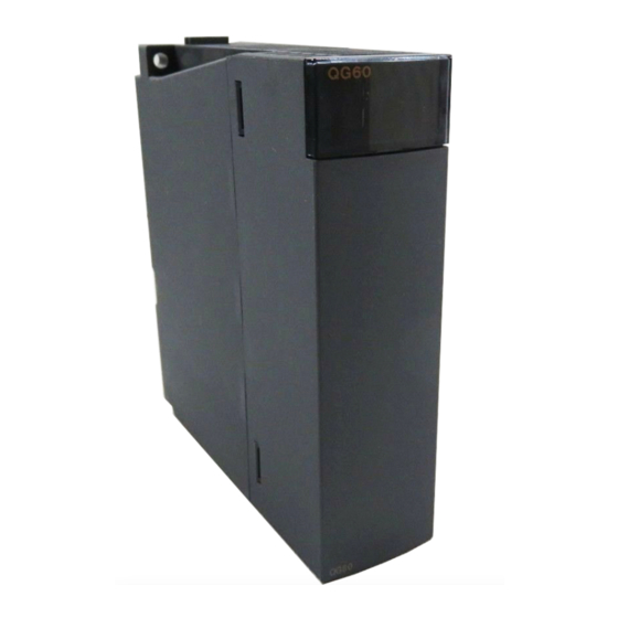
6 BLANK COVER MODULE MELSEC-Q 6. BLANK COVER MODULE This chapter provides the specifications of the blank cover module used to protect the vacant slot (between I/O modules) of the base unit from dust. Table 6.1 Blank Cover Module Specifications Type QG60 Item... - Page 109 6 BLANK COVER MODULE MELSEC-Q MEMO 6 - 2 6 - 2...
-
Page 110: Connectors
7 CONNECTORS MELSEC-Q 7. CONNECTORS The 40-pin connectors and 37-pin D-sub connectors used with the input and output modules are to be user-prepared. The following tables list the connector types and applicable models, and introduce crimp-contact and pressure-displacement tools. (1) 40-pin connectors (a) 40-pin connectors Type Model name... - Page 111 7 CONNECTORS MELSEC-Q (2) 37-pin D-sub connectors (a) 37-pin D-sub connectors Type Model name Applicable wire size Applicable model Soldering type connector 0.088 to 0.3mm A6CON1E (straight out type) (28 to 22 AWG) (stranded wire) Crimp-contact type connector A6CON2E 24 to 20 AWG (stranded wire) QX81, QX81-S2, QY81P (straight out type) Pressure-displacement type connector...
-
Page 112: Specifications Of Connector/Terminal Block Converter Modules
8 SPECIFICATIONS OF CONNECTOR/TERMINAL BLOCK CONVERTER MODULES MELSEC-Q 8. SPECIFICATIONS OF CONNECTOR/TERMINAL BLOCK CONVERTER MODULES 8.1 Specifications of Connector/Terminal Block Converter Modules This chapter explains the specifications of connector/terminal block converter modules. (1) Connector/terminal block converter module Applicable Applicable Type Details Weight crimping... - Page 113 8 SPECIFICATIONS OF CONNECTOR/TERMINAL BLOCK CONVERTER MODULES MELSEC-Q POINT (1) The number of connectable I/O points is 32 for all connector/terminal block converter modules. Two connector/terminal block converter modules and two cables for connector/terminal block converter modules are required for 64-point I/O modules.
-
Page 114: Connector/Terminal Block Converter Module Connection Diagrams
8 SPECIFICATIONS OF CONNECTOR/TERMINAL BLOCK CONVERTER MODULES MELSEC-Q 8.2 Connector/terminal block converter module connection diagrams 8.2.1 A6TBXY36 (1) When connecting an input module (2) When connecting an output module (a) Sink type (b) Source type 8 - 3 8 - 3... -
Page 115: A6Tbxy54
8 SPECIFICATIONS OF CONNECTOR/TERMINAL BLOCK CONVERTER MODULES MELSEC-Q 8.2.2 A6TBXY54 (1) When connecting an input module (2) When connecting an output module (a) Sink type (b) Source type 8 - 4 8 - 4... -
Page 116: A6Tbx70
8 SPECIFICATIONS OF CONNECTOR/TERMINAL BLOCK CONVERTER MODULES MELSEC-Q 8.2.3 A6TBX70 8.2.4 A6TBX36-E 8 - 5 8 - 5... -
Page 117: A6Tby36-E
8 SPECIFICATIONS OF CONNECTOR/TERMINAL BLOCK CONVERTER MODULES MELSEC-Q 8.2.5 A6TBY36-E 8.2.6 A6TBX54-E 8 - 6 8 - 6... -
Page 118: A6Tby54-E
8 SPECIFICATIONS OF CONNECTOR/TERMINAL BLOCK CONVERTER MODULES MELSEC-Q 8.2.7 A6TBY54-E 8.2.8 A6TBX70-E 8 - 7 8 - 7... -
Page 119: Spring Clamp Terminal Block
Since this module uses a spring clamp it does not require screw tightening, which greatly reduces the number of wiring procedures. (1) Model name The model name of spring clamp terminal block I/O module is described below. Model type Model name QX10-TS QX40-TS QX80-TS I/O module QY10-TS QY40P-TS... - Page 120 9 SPRING CLAMP TERMINAL BLOCK MELSEC-Q (2) Connecting a cable Strip off about 6.5mm of the cable tip to install the bar solderless terminal to the stripped part. Connect the cable either by the (a) method or by the (b) method described below.
- Page 121 9 SPRING CLAMP TERMINAL BLOCK MELSEC-Q (b) Use of spring clamp terminal block tool 1) Insert the tool all the way inside the square shaped hole of the terminal block. 2) Insert the bar solderless terminal into the circular shaped hole until the connection check indicator comes out, and remove the tool from the hole.
- Page 122 9 SPRING CLAMP TERMINAL BLOCK MELSEC-Q POINT • If the stripped wire is inserted into the corresponding hole without installing the bar solderless terminal, the connection check indicator does not come out. Do not use the stripped wire without installing the bar solderless terminal. •...
- Page 123 The tools and the bar solderless terminals used for wiring the spring clamp terminal block I/O module are listed below. Manufacturer Name of product Model name Applicable wire size Mitsubishi Electric System & Service Co., Spring clamp terminal block KD-5339 ― Ltd. tool 0.3 to 0.5 mm...
- Page 124 9 SPRING CLAMP TERMINAL BLOCK MELSEC-Q 9.2 Spring Clamp Terminal Block (Q6TE-18S, Q6TE-18SN) The Q6TE-18S and Q6TE-18SN (hereafter abbreviated as Q6TE-18S(N)) shall be used attached to a Q Series terminal block type I/O module or an intelligent function module. Since the Q6TE-18S(N) uses a spring clamp it does not require screw tightening, which greatly reduces the number of wiring procedures.
- Page 125 9 SPRING CLAMP TERMINAL BLOCK MELSEC-Q (4) Installing the Q6TE-18S(N) (a) Remove the protection cap from the Q6TE-18S(N). (b) Mount the Q6TE-18S(N) onto the module and tighten the terminal block mounting screws within the specified torque range. Module Q6TE-18S(N) Terminal block mounting screw *1: Keep the protection cap after removing it.
- Page 126 9 SPRING CLAMP TERMINAL BLOCK MELSEC-Q (6) Connecting a cable (a) When using the bar solderless terminal, correctly connect a wire to the solderless terminal according to the directions for the solderless terminal. When using a wire (single wire or stranded wire), strip the wire to meet the strip length of the specifications.
- Page 127 The tools and the bar solderless terminal used for wiring the spring clamp terminal block I/O module are listed below. Manufacturer Name of product Model name Applicable wire size Mitsubishi Electric System & Service Co., Spring clamp terminal ― KD-5339 Ltd. block tool 0.3 to 0.5 mm...
-
Page 128: Part Names
10 PART NAMES MELSEC-Q 10. PART NAMES This chapter explains the part names of I/O modules. 18-point screw terminal block type (other than 40-pin connector type high-speed input module) QX10 QX41 QX42 0 1 2 3 4 5 6 7 0 1 2 3 4 5 6 7 0 1 2 3 4 5 6 7 8 9 A B C D E F... - Page 129 10 PART NAMES MELSEC-Q 37-pin D-sub connector type QX81 0 1 2 3 4 5 6 7 8 9 A B C D E F 0 1 2 3 4 5 6 7 8 9 A B C D E F QX81 24VDC Name...
- Page 130 10 PART NAMES MELSEC-Q 18-point screw terminal block type (high-speed input module) View A (enlarged view) Name Description 1) Module fixing hook Hook used to fix the module to the base unit. (Single-motion installation) 2) I/O indicator LED Used to indicate the I/O status (on/off). The corresponding LED turns on when the I/O status is on.
- Page 131 10 PART NAMES MELSEC-Q Spring clamp terminal block type Name Description Hook used to fix the module to the base unit. Module fixing hook (Single-motion installation) Used to indicate the I/O status (on/off). The corresponding LED turns on I/O indicator LED when the I/O status is on.
- Page 132 10 PART NAMES MELSEC-Q A6TB A6TB Name Description Panel mounting hole Used for mounting to panel (for M4 screw). Terminal block Used to connect power and signal wires. Designed for 32-point module and used to connect power and I/O 40-pin connector signal wires.
- Page 133 10 PART NAMES MELSEC-Q A6TBX70 Name Description Panel mounting hole Used for mounting to panel (for M4 screw). Terminal block Used to connect power and signal wires. Designed for 32-point module and used to connect power and I/O 40-pin connector signal wires.
-
Page 134: I/O Module Troubleshooting
11 I/O MODULE TROUBLESHOOTING MELSEC-Q 11. I/O MODULE TROUBLESHOOTING This chapter explains possible problems with I/O circuits and their corrective actions. 11.1 Input Circuit Troubleshooting This section describes possible problems with input circuits and their corrective actions. Table 11.1 Input Circuit Problems and Corrective Actions Condition Cause Corrective action... - Page 135 11 I/O MODULE TROUBLESHOOTING MELSEC-Q Table 11.1 Input Circuit Problems and Corrective Actions (Continued) Condition Cause Corrective action An input • Drive by switch with LED indicator. Connect an appropriate resistor so that the signal does current flow within the module will be less than not turn off.
- Page 136 11 I/O MODULE TROUBLESHOOTING MELSEC-Q <Calculation example of Example 4> Connecting a switch with LED display, in which a maximum 2.33mA leakage current flows when 24VDC is supplied to the QX40. (1) In this case, the circuit does not satisfy the condition that the OFF current of the QX40 is 1.7mA or less.
-
Page 137: Output Circuit Troubleshooting
11 I/O MODULE TROUBLESHOOTING MELSEC-Q 11.2 Output Circuit Troubleshooting This section describes possible problems with output circuits and their corrective actions. Table 11.2 Output Circuit Problems and Corrective Actions Condition Cause Corrective action When the • Load is half-wave rectified inside (in some •... - Page 138 11 I/O MODULE TROUBLESHOOTING MELSEC-Q Table 11.2 Output Circuit Problems and Corrective Actions (Continued) Condition Cause Corrective action The load • If the load current is insufficient (lower than • Connect a resistor to both ends of the load so does not 25mA), the triac does not operate, causing the that the load current of approx.
- Page 139 11 I/O MODULE TROUBLESHOOTING MELSEC-Q Table 11.2 Output Circuit Problems and Corrective Actions (Continued) Condition Cause Corrective action When the (1) To turn on or off the external power supply, Erroneous output due to the stray capacitance (C) between check that the external power supply rising external power collector and emitter of photocoupler.
- Page 140 11 I/O MODULE TROUBLESHOOTING MELSEC-Q Table 11.2 Output Circuit Problems and Corrective Actions (Continued) Condition Cause Corrective action If an inductive load is connected, the load may turn on Take one of the following actions. The load from off ([2]) due to back electromotive force at the (1) To suppress back electromotive force, connect a momentarily time of power-off ([1]).
- Page 141 11 I/O MODULE TROUBLESHOOTING MELSEC-Q Table 11.2 Output Circuit Problems and Corrective Actions (Continued) Condition Cause Corrective action The load The polarity to connect the external power supply is reverse. Connect the external power supply with Transistor operates only by correct polarity.
-
Page 142: Appendices
APPENDICES MELSEC-Q APPENDICES Appendix 1 External Dimensions Appendix 1.1 I/O modules and blank cover module (1) Terminal block connector type (a) Other than QY22 QX10 0 1 2 3 4 5 6 7 8 9 A B C D E F 100VAC 8mA60Hz 7mA50Hz... - Page 143 APPENDICES MELSEC-Q (2) Spring clamp terminal block type QX10-TS 27.4 Unit: mm App - 2 App - 2...
- Page 144 APPENDICES MELSEC-Q (3) 40-pin connector type (a) 32-point I/O module QX41 0 1 2 3 4 5 6 7 8 9 A B C D E F 0 1 2 3 4 5 6 7 8 9 A B C D E F QX41 24VDC 27.4...
- Page 145 APPENDICES MELSEC-Q (4) 37-pin D-sub connector type 32-point I/O module QX81 0 1 2 3 4 5 6 7 8 9 A B C D E F 0 1 2 3 4 5 6 7 8 9 A B C D E F QX81 24VDC 27.4...
-
Page 146: Appendix 1.2 Connectors, Connector/Terminal Block Converter Modules
APPENDICES MELSEC-Q Appendix 1.2 Connectors, connector/terminal block converter modules (1) 40-pin connectors (a) A6CON1 soldering type, A6CON2 crimp-contact type 40-pin connector Unit: mm (b) A6CON3 pressure-displacement type 40-pin connector 69.48 8.25 Flat cable arrangement is in the following sequence. A2… 22.5 Unit: mm App - 5... - Page 147 APPENDICES MELSEC-Q (c) A6CON4 soldering type Unit: mm If the cable diameter is thinner than the clamp portion, wind tape, etc. to secure the cable so that it will not come off the cable clamp portion. If the cable is made of slippery material, it is recommended to take anti-slip measures by winding rubber-based tape, etc.
- Page 148 APPENDICES MELSEC-Q (2) 37-pin D-sub connectors (a) A6CON1E soldering type 37-pin D sub-connector (straight out type) A6CON2E crimp-contact-type 37-pin D sub-connector (straight out type) Unit: mm (b) A6CON3E pressure-displacement type 37-pin D-sub connector (flat cable type) 69.4 12.6 Unit: mm App - 7 App - 7...
- Page 149 APPENDICES MELSEC-Q (3) A6TB connector/terminal block converter module Unit: mm (4) A6TB connector/terminal block converter module Unit: mm (5) A6TBX70 connector/terminal block converter module Unit: mm App - 8 App - 8...
-
Page 150: Appendix 1.3 Connector/Terminal Block Converter Module Cable
APPENDICES MELSEC-Q Appendix 1.3 Connector/terminal block converter module cable (1) AC Unit: mm (2) AC TB-E Unit: mm App - 9 App - 9... -
Page 151: Appendix 1.4 Spring Clamp Terminal Block
APPENDICES MELSEC-Q Appendix 1.4 Spring clamp terminal block (1) Q6TE-18S(N) Installed on a module (Example: QX10) Unit: mm *1: The depth of the module installed with the Q6TE-18S(N) is equivalent with the factory default dimensions for that module. App - 10 App - 10... -
Page 152: Appendix 2 Compatibility With Melsec-Ans Series I/O Modules
APPENDICES MELSEC-Q Appendix 2 Compatibility with MELSEC-AnS Series I/O Modules Note that the MELSEC-Q series I/O modules and MELSEC-AnS series I/O modules are different in external terminal block configuration. Differences in terminal block configuration are indicated below. (1) Input modules Terminal Block A1SX10, A1SX40, QX10, QX40... - Page 153 APPENDICES MELSEC-Q Terminal Terminal Block QY50 A1SY50 Block QY80 A1SY80 Number Number 12/24VDC COM1 TB10 COM1 TB10 TB11 TB11 • • • • • • • • • • • • • • • • • • TB16 TB16 TB17 12/24VDC TB17 TB18...
- Page 154 APPENDICES MELSEC-Q MEMO App - 13 App - 13...
- Page 155 WARRANTY...
- Page 156 Ethernet is a registered trademark of Fuji Xerox Co., Ltd. in Japan. Microsoft and Windows are either registered trademarks or trademarks of Microsoft Corporation in the United States and/or other countries. The company names, system names and product names mentioned in this manual are either registered trademarks or trademarks of their respective companies.
- Page 158 SH(NA)-080042-AD(1802)MEE MODEL: Q-IO-U-E MODEL CODE: 13JL99 HEAD OFFICE : TOKYO BUILDING, 2-7-3 MARUNOUCHI, CHIYODA-KU, TOKYO 100-8310, JAPAN NAGOYA WORKS : 1-14 , YADA-MINAMI 5-CHOME , HIGASHI-KU, NAGOYA , JAPAN When exported from Japan, this manual does not require application to the Ministry of Economy, Trade and Industry for service transaction permission.