Table of Contents
Advertisement
Quick Links
SPI to CAN FD SBC + LIN Transceiver BoosterPack User's
The SPI to CAN FD SBC + LIN BoosterPack™ features the TCAN4550-Q1 CAN FD controller with
integrated transceiver providing microcontrollers without an integrated CAN FD controller, or those
needing additional channels, access to CAN FD applications through a SPI interface. LIN applications can
also be developed using the TLIN2029-Q1 fault protected LIN transceiver and the MCU UART port
making this BoosterPack an ideal starting point for any CAN FD or LIN system.
spacer
...................................................................................................................
1
1.1
2
2.1
2.2
....................................................................................................................
2.3
2.4
....................................................................................................................
3
3.1
3.2
3.3
3.4
4
5
5.1
5.2
1
2
3
4
5
.......................................................................................................................
6
7
8
9
10
11
12
13
14
15
16
..............................................................................................................
.......................................................................................................
................................................................................................................
..................................................................................................................
........................................................................................
........................................................................................
.......................................................................................
................................................................................................................
...........................................................................................
..........................................................................................................
....................................................................................................
.....................................................................................................
.........................................................................................
......................................................................................
........................................................................................
...........................................................................................................
.............................................................................................
...............................................................................................
........................................................................................
....................................................................................................
..........................................................................................
...........................................................................................................
.......................................................................................................
...................................................................................................
Copyright © 2019, Texas Instruments Incorporated
.......................................................................
.......................................................................
List of Figures
...............................................................................
.............................................................................
User's Guide
SLLU216 - July 2019
Guide
2
2
3
4
7
8
9
14
14
16
17
18
22
23
23
25
3
4
7
8
10
10
14
15
18
19
20
20
21
22
23
24
1
Advertisement
Table of Contents

Related Manuals for Texas Instruments TLIN2029-Q1


Summary of Contents for Texas Instruments TLIN2029-Q1
-
Page 1: Table Of Contents
CAN FD applications through a SPI interface. LIN applications can also be developed using the TLIN2029-Q1 fault protected LIN transceiver and the MCU UART port making this BoosterPack an ideal starting point for any CAN FD or LIN system. -
Page 2: Contents 1 Introduction
CAN FD applications through a SPI interface. LIN applications can also be developed using the TLIN2029-Q1 fault protected LIN transceiver and the MCU UART port making this BoosterPack an ideal starting point for any CAN FD or LIN system. -
Page 3: Hardware Description
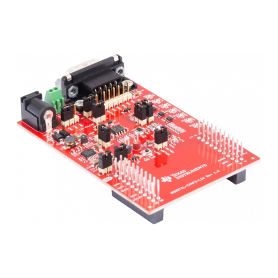
Hardware description www.ti.com Hardware description Figure 1. BOOSTXL-CANFN-LIN SLLU216 – July 2019 SPI to CAN FD SBC + LIN Transceiver BoosterPack User's Guide Submit Documentation Feedback Copyright © 2019, Texas Instruments Incorporated... -
Page 4: Power
≤ 5 V. The TCAN4550-Q1 operates across a range of 6 V to 24 V with an absolute maximum voltage of 40 V, the TLIN2029-Q1 operates across a range of 4 V to 48 V with an absolute maximum voltage of 60 V, and the TPS7B7702-Q1 operates across a range of 4.5 V to 40 V with... - Page 5 2.1.3.2 GND Pin GND is the TLIN2029-Q1 ground connection. The device can operate with a ground shift as long as the ground shift does not reduce the V below the minimum operating voltage. If there is a loss of ground at the ECU level, the device has extremely low leakage from the LIN pin, and does not load the bus down.
- Page 6 J11 and J12 are removed when the LaunchPad is powered from the debugger. While the TLIN2029-Q1 does not support a wake and inhibit feature, the BoosterPack was designed to support LIN transceivers that do contain those features allowing the LIN transceiver to also control the LDO's enable pin in conjunction with or instead of the TCAN4550-Q1.
-
Page 7: Can
J6 and J9 disconnects the local termination from the CANH and CANL lines. SLLU216 – July 2019 SPI to CAN FD SBC + LIN Transceiver BoosterPack User's Guide Submit Documentation Feedback Copyright © 2019, Texas Instruments Incorporated... -
Page 8: Lin
CANH/CANL) TVS Di ode and LIN Bu s Signa l Loa ding Heade r Capacitors SPI to CAN FD SBC + LIN Transceiver BoosterPack User's Guide SLLU216 – July 2019 Submit Documentation Feedback Copyright © 2019, Texas Instruments Incorporated... -
Page 9: Mcu Interface (Spi/Gpio)
A SOD323 TVS diode footprint has been added to the BoosterPack and diodes installed to provide maximum protection when used in environments that may not have proper ESD controls. However, the use of these external diodes are considered optional and the TLIN2029-Q1 contains robust internal ESD protection. -
Page 10: Mcu Interface Components And Features
Many BoosterPack modules can be stacked onto your LaunchPad for additional functionality. More information about compatibility can also be found at http://www.ti.com/launchpad. SPI to CAN FD SBC + LIN Transceiver BoosterPack User's Guide SLLU216 – July 2019 Submit Documentation Feedback Copyright © 2019, Texas Instruments Incorporated... - Page 11 32 bits shifted in to the device during one SPI transaction (nCS low) the last word of the transfer is ignored, the SPIERR flag is set. SLLU216 – July 2019 SPI to CAN FD SBC + LIN Transceiver BoosterPack User's Guide Submit Documentation Feedback Copyright © 2019, Texas Instruments Incorporated...
- Page 12 16'h0800[11:10]. To configure the pin to support a watchdog input timer reset pin use SPI register 16'h0800[15:14] = 10. SPI to CAN FD SBC + LIN Transceiver BoosterPack User's Guide SLLU216 – July 2019 Submit Documentation Feedback Copyright © 2019, Texas Instruments Incorporated...
- Page 13 I/O supply voltage is required. In standby mode the RXD pin is driven low to indicate a wake up request from the LIN bus. SLLU216 – July 2019 SPI to CAN FD SBC + LIN Transceiver BoosterPack User's Guide Submit Documentation Feedback Copyright © 2019, Texas Instruments Incorporated...
-
Page 14: Firmware
SPI to CAN FD SBC + LIN Transceiver BoosterPack User's Guide SLLU216 – July 2019 Submit Documentation Feedback Copyright © 2019, Texas Instruments Incorporated... -
Page 15: Visual Representation Of Mram Allocation
0x8010 Rx FIFO 0 0x80F0 Rx FIFO 1 0x8258 Tx Event FIFO 0x8270 Tx Buffers 0x87FF SLLU216 – July 2019 SPI to CAN FD SBC + LIN Transceiver BoosterPack User's Guide Submit Documentation Feedback Copyright © 2019, Texas Instruments Incorporated... -
Page 16: Sending And Receiving Can Messages
2. Read TXFQS.TFQPI to get which index the message should be loaded into. 3. Calculate the memory offset to determine the start address in the MRAM memory. SPI to CAN FD SBC + LIN Transceiver BoosterPack User's Guide SLLU216 – July 2019 Submit Documentation Feedback Copyright © 2019, Texas Instruments Incorporated... -
Page 17: Performance Optimization
Structuring the code to minimize these idle times ensures that maximum possible CAN throughput is possible. SLLU216 – July 2019 SPI to CAN FD SBC + LIN Transceiver BoosterPack User's Guide Submit Documentation Feedback Copyright © 2019, Texas Instruments Incorporated... -
Page 18: Microcontroller Abstraction
Run Time Environment (RTE) Services Layer AutoSAR ECU Abstraction Layer MCAL Microcontroller / Processor Hardware TCAN4x5x SPI to CAN FD SBC + LIN Transceiver BoosterPack User's Guide SLLU216 – July 2019 Submit Documentation Feedback Copyright © 2019, Texas Instruments Incorporated... -
Page 19: Microcontroller Abstraction
Firmware www.ti.com Texas Instruments provides the necessary ECU abstraction layer driver source code necessary to integrate the TCAN4550-Q1 into an AutoSAR environment. Contact TI to get the source code. The demo firmware provided is a lower-level API for controlling various TCAN4550-Q1 functions and sending and receiving CAN messages. -
Page 20: 32-Bit Spi Read Or Write Example
SPI header. The END function is responsible for pulling the CS high, to signal the end of the transfer. SPI to CAN FD SBC + LIN Transceiver BoosterPack User's Guide SLLU216 – July 2019 Submit Documentation Feedback Copyright © 2019, Texas Instruments Incorporated... -
Page 21: Multi-Word Spi Packet Example
This is helpful for cutting down on the SPI overhead when transferring a CAN message to or from the TCAN4550-Q1, and minimize the maximum SPI frequency required. SLLU216 – July 2019 SPI to CAN FD SBC + LIN Transceiver BoosterPack User's Guide Submit Documentation Feedback Copyright © 2019, Texas Instruments Incorporated... -
Page 22: Board Layout
Figure 14 Figure 15 show the top and bottom of the BoosterPack. Figure 14. BoosterPack Top SPI to CAN FD SBC + LIN Transceiver BoosterPack User's Guide SLLU216 – July 2019 Submit Documentation Feedback Copyright © 2019, Texas Instruments Incorporated... -
Page 23: Schematic And Bill Of Materials
Figure 15. BoosterPack Bottom Schematic and Bill of Materials Schematic Figure 16 is a schematic diagram of the BoosterPack. SLLU216 – July 2019 SPI to CAN FD SBC + LIN Transceiver BoosterPack User's Guide Submit Documentation Feedback Copyright © 2019, Texas Instruments Incorporated... -
Page 24: Boosterpack Schematic
Not in version control Assembly Variant: Sheet: warrant that this design will meet the specifications, will be suitable for your application or fit for any particular purpose, or will operate in an implementation. Texas Instruments and/or its Drawn By: Jonathan Nerger File: INT107A_Schematic.SchDoc... -
Page 25: Bill Of Materials
LED_0603 150060RS75000 Wurth Elektronik J1, J4, J15 Header, 100mil, 3x1, Gold, TH 3x1 Header TSW-103-07-G-S Samtec SLLU216 – July 2019 SPI to CAN FD SBC + LIN Transceiver BoosterPack User's Guide Submit Documentation Feedback Copyright © 2019, Texas Instruments Incorporated... -
Page 26: Spi To Can Fd Sbc + Lin Transceiver Boosterpack User's Guide
CRCW04021K50FKED Vishay-Dale 17.4k RES, 17.4 k, 1%, 0.063 W, AEC-Q200 Grade 0, 0402 0402 CRCW040217K4FKED Vishay-Dale SPI to CAN FD SBC + LIN Transceiver BoosterPack User's Guide SLLU216 – July 2019 Submit Documentation Feedback Copyright © 2019, Texas Instruments Incorporated... - Page 27 RES, 33.2 k, 1%, 0.063 W, AEC-Q200 Grade 0, 0402 0402 CRCW040233K2FKED Vishay-Dale 10.0k RES, 10.0 k, 1%, 0.063 W, 0402 0402 RC0402FR-0710KL Yageo America SLLU216 – July 2019 SPI to CAN FD SBC + LIN Transceiver BoosterPack User's Guide Submit Documentation Feedback Copyright © 2019, Texas Instruments Incorporated...
- Page 28 STANDARD TERMS FOR EVALUATION MODULES Delivery: TI delivers TI evaluation boards, kits, or modules, including any accompanying demonstration software, components, and/or documentation which may be provided together or separately (collectively, an “EVM” or “EVMs”) to the User (“User”) in accordance with the terms set forth herein.
- Page 29 www.ti.com Regulatory Notices: 3.1 United States 3.1.1 Notice applicable to EVMs not FCC-Approved: FCC NOTICE: This kit is designed to allow product developers to evaluate electronic components, circuitry, or software associated with the kit to determine whether to incorporate such items in a finished product and software developers to write software applications for use with the end product.
- Page 30 www.ti.com Concernant les EVMs avec antennes détachables Conformément à la réglementation d'Industrie Canada, le présent émetteur radio peut fonctionner avec une antenne d'un type et d'un gain maximal (ou inférieur) approuvé pour l'émetteur par Industrie Canada. Dans le but de réduire les risques de brouillage radioélectrique à...
- Page 31 www.ti.com EVM Use Restrictions and Warnings: 4.1 EVMS ARE NOT FOR USE IN FUNCTIONAL SAFETY AND/OR SAFETY CRITICAL EVALUATIONS, INCLUDING BUT NOT LIMITED TO EVALUATIONS OF LIFE SUPPORT APPLICATIONS. 4.2 User must read and apply the user guide and other available documentation provided by TI regarding the EVM prior to handling or using the EVM, including without limitation any warning or restriction notices.
- Page 32 Notwithstanding the foregoing, any judgment may be enforced in any United States or foreign court, and TI may seek injunctive relief in any United States or foreign court. Mailing Address: Texas Instruments, Post Office Box 655303, Dallas, Texas 75265 Copyright © 2019, Texas Instruments Incorporated...
- Page 33 TI products. TI’s provision of these resources does not expand or otherwise alter TI’s applicable warranties or warranty disclaimers for TI products. Mailing Address: Texas Instruments, Post Office Box 655303, Dallas, Texas 75265 Copyright © 2019, Texas Instruments Incorporated...
- Page 34 Mouser Electronics Authorized Distributor Click to View Pricing, Inventory, Delivery & Lifecycle Information: Texas Instruments BOOSTXL-CANFD-LIN...