Table of Contents
Advertisement
Available languages
Available languages
Quick Links
Advertisement
Table of Contents

Related Manuals for MSI 870A-G55 Series


Summary of Contents for MSI 870A-G55 Series
- Page 1 870A-G55/ 870U-G55 series MS-7599 (v5.x) Mainboard G52-75991XR...
-
Page 2: Trademarks
Alternatively, please try the following help resources for further guidance. ◙ Visit the MSI website for FAQ, technical guide, BIOS updates, driver updates, and other information: http://www.msi.com/index.php?func=service ◙ Contact our technical staff at: http://ocss.msi.com... -
Page 3: Safety Instructions
MS-7599 MS-7599 Safety Instructions ■ Always read the safety instructions carefully. ■ Keep this User’s Manual for future reference. ■ Keep this equipment away from humidity. ■ Lay this equipment on a reliable flat surface before setting it up. ■ The openings on the enclosure are for air convection hence protects the equipment from overheating. -
Page 4: Fcc-B Radio Frequency Interference Statement
Preface Preface FCC-B Radio Frequency Interference Statement This equipment has been tested and found to comply with the limits for a Class B digi- tal device, pursuant to Part 15 of the FCC Rules. These limits are designed to provide reasonable protection against harmful inter- ference in a residential installation. -
Page 5: Weee (Waste Electrical And Electronic Equipment) Statement
MSI will comply with the product take back requirements at the end of life of MSI-branded products that are sold into the EU. - Page 6 MSI će poštovati zahtev o preuzimanju ovakvih proizvoda kojima je istekao vek trajanja, koji imaju MSI oznaku i koji su prodati u EU. Ove proiz- vode možete vratiti na lokalnim mestima za prikupljanje.
- Page 7 MSI si adeguerà a tale Direttiva ritirando tutti i prodotti marchiati MSI che sono stati venduti all’interno dell’Unione Europea alla fine del loro...
-
Page 8: Table Of Contents
Preface Preface Contents Copyright Notice .................... ii Trademarks ....................ii Revision History..................... ii Technical Support..................ii Safety Instructions ..................iii FCC-B Radio Frequency Interference Statement.......... iv WEEE (Waste Electrical and Electronic Equipment) Statement ....v English ...................... En-1 Mainboard Specifications ...................En-2 Quick Components Guide ..................En-4 Screw Holes .......................En-5 CPU (Central Processing Unit) ................En-6... - Page 9 MS-7599 MS-7599 Français ..................... Fr-1 Spécifications ......................Fr-2 Guide Rapide Des Composants ................Fr-4 Trous Taraudés ....................Fr-5 Processeur : CPU ....................Fr-6 Mémoire ......................Fr-9 Connecteurs d’alimentation ................Fr-11 Panneau arrière ....................Fr-12 Connecteurs ......................Fr-14 Cavalier ......................Fr-21 Bouton .......................Fr-22 Emplacements ....................Fr-23 Indicateur de statut LED ..................Fr-24 Réglage BIOS ....................Fr-25 Information De Logiciel ..................Fr-35 Русский...
-
Page 11: English
English 870A-G55/ 870U-G55 Series Europe version... -
Page 12: Mainboard Specifications
■ Phenom II series, Athlon II series and Sempron series processor in the ® AM3 package. (For the latest information about CPU, please visit http://www.msi.com/index. php?func=cpuform2) HyperTransport ■ HyperTransport™ 3.0, supports up to 5.2 GT/s Chipset ■ North Bridge: AMD RX780 chipset ®... - Page 13 ■ ATX (22.5 cm X 30.5 cm) Mounting ■ 6 mounting holes * If you need to purchase accessories and request the part numbers, you could search the product web page and find details on our web address http://www.msi.com/index. En-3...
-
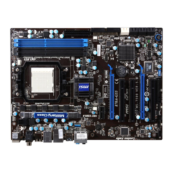
Page 14: Quick Components Guide
MS-7599 Mainboard MS-7599 Mainboard Quick Components Guide JTPM1, En-20 CPU, En-6 DDR3, En-9 JPWR2, En-11 CPUFAN1, En-16 SYSFAN1, En-16 Back Panel, En-12 SYSFAN2, En-16 JPWR1, En-11 USB3, En-18 IDE1, En-14 PCIE, En-23 JCI1, En-15 SATA, En-15 PCI, En-23 JBAT1, En-21 JCD1, En-18 TURBO1, En-22 JFP1/ JFP2, En-17... -
Page 15: Screw Holes
Screw Holes When you install the mainboard, you have to place the mainboard into the chassis in the correct direction. The locations of screws holes on the mainboard are shown as below. The side has to toward the rear, the position for the I/O shield of the chassis. -
Page 16: Cpu (Central Processing Unit
When you are installing the CPU, make sure to install the cooler to prevent overheating. If you do not have the CPU cooler, consult your dealer before turning on the computer. For the latest information about CPU, please visit http://www.msi.com/index. php?func=cpuform2... - Page 17 CPU & Cooler Installation When you are installing the CPU, make sure the CPU has a cooler attached on the top to prevent overheating. Meanwhile, do not forget to apply some thermal paste on CPU before installing the heat sink/cooler fan for better heat dispersion. Follow the steps below to install the CPU &...
- Page 18 MS-7599 Mainboard MS-7599 Mainboard Position the cooling set onto the re- Then press down the other end of the tention mechanism. clip to fasten the cooling set on the Hook one end of the clip to hook top of the retention mechanism. first.
-
Page 19: Memory
Memory These DIMM slots are used for installing memory modules. For more information on compatible components, please visit http://www.msi.com/index.php?func=testreport DDR3 240-pin, 1.5V 72x2=144 pin 48x2=96 pin Dual-Channel mode Population Rule In Dual-Channel mode, the memory modules can transmit and receive data with two data bus lines simultaneously. - Page 20 MS-7599 Mainboard MS-7599 Mainboard Installing Memory Modules The memory module has only one notch on the center and will only fit in the right orientation. Insert the memory module vertically into the DIMM slot. Then push it in until the golden finger on the memory module is deeply inserted in the DIMM slot.
-
Page 21: Power Supply
Power Supply ATX 24-pin Power Connector: JPWR1 This connector allows you to connect an ATX 24-pin power supply. To connect the ATX 24-pin power supply, make sure the plug of the power supply is inserted in the proper orientation and the pins are aligned. Then push down the power supply firmly into the connector. -
Page 22: Back Panel
MS-7599 Mainboard MS-7599 Mainboard Back Panel Coaxial IEEE 1394 Port Mouse S/PDIF-Out Line-In RS-Out Clear CMOS Line-Out CS-Out Button SS-Out Keyboard USB 2.0 Port USB 2.0 Port USB 3.0 Port Optical USB 2.0 Port S/PDIF-Out ▶ Mouse/Keyboard The standard PS/2 mouse/keyboard DIN connector is for a PS/2 mouse/keyboard. - Page 23 ▶ IEEE 1394 Port (optional) The IEEE 1394 port on the back panel provides connection to IEEE 1394 devices. ▶ USB 3.0 Port USB 3.0 port is backward-compatible with USB 2.0 devices. It supports data transfer rate up to 5 Gbit/s (SuperSpeed). Important If you want to use a USB 3.0 device, you must use the USB 3.0 cable to connect to the USB 3.0 port.
-
Page 24: Connectors
MS-7599 Mainboard MS-7599 Mainboard Connectors Floppy Disk Drive Connector: FDD1 This connector supports 360 KB, 720 KB, 1.2 MB, 1.44 MB or 2.88 MB floppy disk drive. * The MB layout in this figure is for reference only. IDE Connector: IDE1 This connector supports IDE hard disk drives, optical disk drives and other IDE de- vices. - Page 25 Serial ATA Connector: SATA1~8 This connector is a high-speed Serial ATA interface port. Each connector can connect to one Serial ATA device. * The MB layout in this figure is for reference only. SATA7/ SATA8 (6Gb/s) SATA7_8 supported by Marvell 88SE9128 (optional) ®...
- Page 26 MS-7599 Mainboard MS-7599 Mainboard Fan Power Connectors: CPUFAN1, SYSFAN1~2 The fan power connectors support system cooling fan with +12V. When connecting the wire to the connectors, always note that the red wire is the positive and should be con- nected to the +12V; the black wire is Ground and should be connected to GND. If the mainboard has a System Hardware Monitor chipset on-board, you must use a specially designed fan with speed sensor to take advantage of the CPU fan control.
- Page 27 Front Panel Connectors: JFP1, JFP2 These connectors are for electrical connection to the front panel switches and LEDs. The JFP1 is compliant with Intel Front Panel I/O Connectivity Design Guide. ® JFP2 JFP1 S/PDIF-Out Connector: JSP1 This connector is used to connect S/PDIF (Sony & Philips Digital Interconnect Format) interface for digital audio transmission.
- Page 28 MS-7599 Mainboard MS-7599 Mainboard Front USB Connector: JUSB1 / JUSB2 / USB3 In addition to being compliant with Intel® I/O Connectivity Design Guide, this connector is also ideal for connecting high-speed USB interface peripherals such as USB HDD, digital cameras, MP3 players, printers, modems and the like. USB 2.0 connector: JUSB1/ JUSB2 * The MB layout in this figure is for reference only.
- Page 29 IEEE 1394 Connector: J1394_1 This connector allows you to connect the IEEE 1394 device via an optional IEEE1394 bracket. * The MB layout in this figure is for reference only. 1394 Bracket (optional) Serial Port Connector: JCOM1 This connector is a 16550A high speed communication port that sends/ receives 16 bytes FIFOs.
- Page 30 MS-7599 Mainboard MS-7599 Mainboard TPM Module connector: JTPM1 This connector connects to a TPM (Trusted Platform Module) module (optional). Please refer to the TPM security platform manual for more details and usages. En-20...
-
Page 31: Jumpers
Jumpers Clear CMOS Jumper: JBAT1 There is a CMOS RAM on board with an external battery power supply to preserve the system configuration data. With the CMOS RAM, the system can automatically boot OS every time it is turned on. If you want to clear the system configuration, set the jumper to clear data. -
Page 32: Button
You can disable the OC Genie function in BIOS setup. And we suggest you to save the OC Genie configuration to overclocking profile in BIOS for future using. The usage of OC Genie is at your own risk. Overclocking is never guaranteed by • MSI. En-22... -
Page 33: Slots
Slots PCIE (Peripheral Component Interconnect Express) Slot The PCIE slot supports the PCIE interface expansion card. PCIE x16 Slot PCIE x1 Slot PCI (Peripheral Component Interconnect) Slot The PCI slot supports LAN card, SCSI card, USB card, and other add-on cards that comply with PCI specifications. -
Page 34: Led Status Indicators
MS-7599 Mainboard MS-7599 Mainboard LED Status Indicators CPU Phase LEDs These LEDs indicate the current CPU power phase mode. Follow the instructions below to read. Lights CPU is in 1 phase power mode. CPU is in 4 phase power mode. En-24... -
Page 35: Bios Setup
BIOS Setup This chapter provides basic information on the BIOS Setup program and allows you to configure the system for optimum use. You may need to run the Setup program when: ■ An error message appears on the screen during the system booting up, and requests you to run BIOS SETUP. - Page 36 MS-7599 Mainboard MS-7599 Mainboard Entering Setup Power on the computer and the system will start POST (Power On Self Test) process. When the message below appears on the screen, press <DEL> key to enter Setup. Press DEL to enter SETUP If the message disappears before you respond and you still wish to enter Setup, restart the system by turning it OFF and On or pressing the RESET button.
- Page 37 The Main Menu Once you enter BIOS CMOS Setup Utility, the Main Menu will appear on the screen. The Main Menu allows you to select from the setup functions and two exit choices. Use arrow keys to select among the items and press <Enter> to accept or enter the sub-menu.
- Page 38 MS-7599 Mainboard MS-7599 Mainboard ▶ M-Flash Use this menu to read/ flash the BIOS from storage drive (FAT/ FAT32 format only). ▶ Overclocking Profile Use this menu to save/ load your settings to/ from CMOS for BIOS. ▶ Load Fail-Safe Defaults Use this menu to load the default values set by the BIOS vendor for stable system performance.
- Page 39 Select [Ok] and press Enter to save the configurations and exit BIOS Setup utility. Important The configuration above are for general use only. If you need the detailed settings of BIOS, please see the English manual on MSI website. En-29...
- Page 40 MS-7599 Mainboard MS-7599 Mainboard Cell Menu Introduction : This menu is for advanced user who want to overclock the mainboard. Important Change these settings only if you are familiar with the chipset. ▶ Current CPU / DRAM / CPU-NB Frequency These items show the current clocks of CPU, Memory and CPU-NB speed.
- Page 41 Enter Windows, and select [Start]->[Settings]->[Control Panel]->[Power Options]. • Enter Power Options Properties tag, and select Minimal Power Management under Power schemes. ▶ C1E Support To enable this item to read the CPU power consumption while idle. Not all proces- sors support Enhanced Halt state (C1E). ▶...
- Page 42 MS-7599 Mainboard MS-7599 Mainboard ▶ Unlock CPU Core This item is used to unlock the CPU core. Please refer to the procedures below for CPU core unlocked in BIOS setup. Enter “Cell Menu” and set “Unlock CPU Core” to [Enabled]. Set “Adjust CPU-NB Ratio”...
- Page 43 ▶ Advance DRAM Configuration Press <Enter> to enter the sub-menu. ▶ DRAM Timing Mode This field has the capacity to automatically detect all of the DRAM timing. ▶ DRAM Drive Strength This item allows you to control the memory data bus’ signal strength. Increasing the drive strength of the memory bus can increase stability during overclocking.
- Page 44 MS-7599 Mainboard MS-7599 Mainboard ▶ Adjusted HT Link Frequency (MHz) It shows the adjusted HT Link frequency. Read-only. ▶ Adjust PCI-E Frequency (MHz) This field allows you to select the PCIE frequency (in MHz). ▶ Auto Disable DRAM/PCI Frequency When set to [Enabled], the system will remove (turn off) clocks from empty DRAM/ PCI slots to minimize the electromagnetic interference (EMI).
-
Page 45: Software Information
Utility menu : The Utility menu shows the software applications that the mainboard supports. Important Please visit the MSI website to get the latest drivers and BIOS for better system per- formance. En-35... -
Page 47: Deutsch
Deutsch 870A-G55/ 870U-G55 Serie Europe Version... -
Page 48: Spezifikationen
■ DDR3 1600 *(OC)/ 1333/ 1066/ 800 DRAM (gesamt max.16GB) ■ 4 DDR3 DIMMs, unterstützt die Modus Dual-Kanal (* OC= Übertaktung, weitere Informationen zu kompatiblen Speichermodulen finden Sie unter http://www.msi.com/index.php?func=testreport) ■ Unterstützt Gb LAN (10/100/1000) über Realtek RTL8111E ® IEEE 1394 ■... - Page 49 BIOS einstellen, kann die SATA 6 Gb/s Anschlüsse (SATA7~8) und den PCIE x1- Steckplatz deaktivieren. Form Faktor ■ ATX (22,5 cm X 30,5 cm) Montage ■ 6 Montagebohrungen * Wenn Sie für Bestellungen von Zubehör Teilenummern benötigen, finden Sie diese auf unserer Produktseite unter http://www.msi.com/index.php De-3...
-
Page 50: Komponenten-Übersicht
MS-7599 Mainboard MS-7599 Mainboard Komponenten-Übersicht JTPM1, De-20 CPU, De-6 DDR3, De-9 JPWR2, De-11 CPUFAN1, De-16 SYSFAN1, De-16 Rücktafel, De-12 SYSFAN2, De-16 JPWR1,De-11 USB3, De-18 IDE1, De-14 PCIE, De-23 JCI1, De-15 SATA, De-15 PCI, De-23 JBAT1, De-21 JCD1, De-18 TURBO1, De-22 JFP1/ JFP2, De-17 JAUD1, De-16 JUSB1~2, De-18... -
Page 51: Schraubenlöcher
Schraubenlöcher Wenn Sie das Mainboard zu installieren, müssen Sie das Mainboard in das Chassis in der korrekten Richtung setzen. Die Standorte von Schraubenlöchern auf dem Main- board sind wie nachfolgend gezeigt. Die Seite muss nach hinten, die Position für E/A-Abschirmung des Chassis. -
Page 52: Cpu (Prozessor
Überhitzung zu vermeiden. Verfügen Sie über keinen Kühler, setzen Sie sich bitte mit Ihrem Händler in Verbindung, um einen solchen zu erwerben und zu installieren. Um die neuesten Informationen zu unterstützten Prozessoren zu erhalten, besuchen Sie bitte http://www.msi.com/index.php?func=cpuform2 Wichtig Überhitzung Überhitzung beschädigt die CPU und das System nachhaltig. - Page 53 CPU & Kühler Einbau Wenn Sie die CPU einbauen, stellen Sie bitte sicher, dass Sie auf der CPU einen Kühler anbringen, um Überhitzung zu vermeiden. Vergessen Sie nicht, etwas Siliziumwärmel- eitpaste auf die CPU aufzutragen, bevor Sie den Prozessorkühler installieren, um eine Ableitung der Hitze zu erzielen.
- Page 54 MS-7599 Mainboard MS-7599 Mainboard Setzen Sie den Kühler auf die Küh- Dann drücken Sie das andere Ende lerhalterung und hacken Sie zuerst des Bügels herunter, um den Kühler ein Ende des Kühlers an dem Modul auf der Kühlerhalterung zu fixieren . fest.
-
Page 55: Speicher
Speicher Diese DIMM-Steckplätze nehmen Arbeitsspeichermodule auf. Die neusten Infor- mationen über kompatible Bauteile finden Sie unter http://www.msi.com/index. php?func=testreport DDR3 240-polig, 1,5V 72x2=144 Pole 48x2=96 Pole Populationsregeln für Dual-Channel-Speicher Im Dual -Channel-Modus können Arbeitsspeichermodule Daten über zwei Datenbuslei- tungen gleichzeitig senden und empfangen. Durch Aktivierung des Dual-Channel-Mo- dus wird die Leistung Ihres Systems verbessert. - Page 56 MS-7599 Mainboard MS-7599 Mainboard Vorgehensweise beim Einbau von Speicher Modulen Die Speichermodulen haben nur eine Kerbe in der Mitte des Moduls. Sie passen nur in einer Richtung in den Sockel. Stecken Sie das Arbeitsspeichermodul senkrecht in den DIMM-Steckplatz ein. Drücken Sie anschließnd das Arbeitsspeichermodul nach unten, bis die Kontakt- seite richtig tief in dem DIMM-Steckplatz sitzt.
-
Page 57: Stromversorgung
Stromversorgung ATX 24-poliger Stromanschluss: JPWR1 Mit diesem Anschluss verbinden Sie den ATX 24-poligen Anschluss des Netzteils. Achten Sie bei dem Verbinden des ATX 24-poligen Stromanschlusses darauf, dass der Anschluss des Netzteils richtig auf den Anschluss an der Hauptplatine ausgerichtet ist. Drücken Sie dann den Anschluss des Netzteils fest nach unten, um eine richtige Verbindung zu gewährleisten. -
Page 58: Rücktafel
MS-7599 Mainboard MS-7599 Mainboard Rücktafel koaxialer IEEE 1394 S/PDIF- Maus Anschluss Ausgang Line-In RS-Out CMOS leeren- Line-Out CS-Out Taste SS-Out Tastatur USB 2.0 USB 2.0 USB 3.0 optischer Anschluss Anschluss USB 2.0 Anschluss S/PDIF- Anschluss Ausgang ▶ Maus/Tastatur Die Standard PS/2 Maus/Tastatur Stecker Mini DIN ist für eine PS/2 Maus/Tastatur. - Page 59 ▶ IEEE 1394 Anschluss (optional) Das IEEE 1394 Anschluss auf der hintere Anschlusspanel zu den Vorrichtungen IEEE1394. ▶ USB 3.0 Anschluss USB 3.0 Anschluss ist abwärtskompatibel mit USB 2.0-Geräten. Unterstützt Daten- transferraten bis 5 Gbit/s (SuperSpeed). Wichtig Wenn Sie ein USB 3.0 Gerät verwenden möchten, müssen Sie das USB 3.0 Kabel verwenden, um an das USB 3.0 Anschluss anzuschließen.
-
Page 60: Anschlüssen
MS-7599 Mainboard MS-7599 Mainboard Anschlüssen Anschluss des Diskettenlaufwerks: FDD1 An diesem Anschluss unterstützt ein Diskettenlaufwerke mit 360KB, 720KB, 1,2MB, 1,44MB oder 2,88MB Kapazität. * Das MB-Layout in dieser Abbildung haben nur Orientierungscharakter. IDE Anschluss: IDE1 An diesem Anschluss können IDE Festplatten, optische Laufwerke und andere Geräte betrieben werden. - Page 61 Serial ATA Anschluss: SATA1~8 Der Anschluss ist eine Hochgeschwindigkeitsschnittstelle der Serial ATA. Pro An- schluss kann ein S-ATA Gerät angeschlossen werden. * Das MB-Layout in dieser Abbildung haben nur Orientierungscharakter. SATA7/ SATA8 (6Gb/s) SATA7_8 werden durch Marvell 88SE9128 (optional) ® unterstützt SATA5_6 SATA1~6 (3Gb/s)
- Page 62 MS-7599 Mainboard MS-7599 Mainboard Stromanschlüsse für Lüfter: CPUFAN1, SYSFAN1~2 Die Anschlüsse unterstützen aktive Systemlüfter mit + 12V. Wenn Sie den Anschluss herstellen, sollten Sie immer darauf achten, dass der rote Draht der positive Pol ist, und mit +12V verbunden werden sollte. Der schwarze Draht ist der Erdkontakt und sollte mit GND verbunden werden.
- Page 63 Frontpanel Anschlüsse: JFP1, JFP2 Diese Anschlüsse sind für das Frontpanel. Sie dienen zum Anschluss der Schalter und LEDs des Frontpanels. JFP1 erfüllt die Anforderungen des “Intel Front Panel I/O Con- ® nectivity Design Guide”. JFP2 JFP1 S/PDIF-Ausgang JSP1 Die SPDIF (Sony & Philips Digital Interconnect Format) Schnittstelle wird für die Über- tragung digitaler Audiodaten verwendet.
- Page 64 MS-7599 Mainboard MS-7599 Mainboard USB Vorderanschluss: JUSB1 / JUSB2 / USB3 Dieser Anschluss entspricht den Richtlinien des Intel I/O Connectivity Design Guide. ® Er ist bestens geeignet, Hochgeschwindigkeits- USB- Peripheriegeräte anzuschließen, wie z.B. USB Festplattenlaufwerke, Digitalkameras, MP3-Player, Drucker, Modems und ähnliches.
- Page 65 IEEE 1394 Anschluss: J1394_1 Mit diesem Anschluss verbinden Sie ein optionales IEEE 1394-Slotblech, das den An- schluss eines IEEE 1394-Gerätes ermöglicht. * Das MB-Layout in dieser Abbildung haben nur Orientierungscharakter. 1394 Slotblech (optional) Serieller Anschluss: JCOM1 Es handelt sich um eine 16550A Kommunikationsschnittstelle, die 16 Bytes FIFOs sendet/empfängt.
- Page 66 MS-7599 Mainboard MS-7599 Mainboard TPM Modul Anschluss: JTPM1 Dieser Anschluss wird für das optionale TPM Modul (Trusted Platform Module) ver- wendt. Weitere Informationen über den Einsatz des optionalen TPM Modules entnehm- en Sie bitte dem TPM Plattform Handbuch. De-20...
-
Page 67: Steckbrücke
Steckbrücke Steckbrücke zur CMOS- Löschung: JBAT1 Der Onboard CMOS Speicher (RAM) wird über eine zusätzliche Betterie mit Strom versorgt, um die Daten der Systemkonfiguration zu speichern. Er ermöglicht es dem Betriebssystem, mit jedem Einschalten automatisch hochzufahren. Wenn Sie die Sys- temkonfiguration löschen wollen, müssen Sie die Steckbrücke für kurze Zeit umsetzen (Löschen Daten). -
Page 68: Tasten
Sie können die OC Genie Funktion in der BIOS-Einstellung sperren. Und wir schla- • gen Sie vor, um die OC Genie Konfiguration zu Übertaktungsprofil im BIOS für die zukunftigen Verwenden zu speichern. • Der Verbrauch von OC Genie ist an Ihrer eigenen Gefahr. Übertaktung wird nie durch MSI garantiert. De-22... -
Page 69: Steckplätze
Steckplätze PCIE (Peripheral Component Interconnect Express) Steckplatz Der PCIE-Steckplatz unterstützt eine Erweiterungskarte mit der PCIE-Schnittstelle. PCIE x16 Steckplatz PCIE x1 Steckplatz PCI (Peripheral Component Interconnect) Steckplatz Der PCI-Steckplatz kann LAN-Karten, SCSI-Karten, USB-Karten und sonstige Zusatz- karten aufnehmen, die mit den PCI-Spezifikationen konform sind. 32-Bit PCI Steckplatz Wichtig Achten Sie darauf, dass Sie zuerst das Netzkabel aus der Steckdose herausziehen,... -
Page 70: Led Statusdikatoren
MS-7599 Mainboard MS-7599 Mainboard LED Statusdikatoren CPU Phase LEDs Diese LEDs zeigen den gegenwärtigen CPU Power-Modus an. Lesen Sie die folgenden Anweisungen. Leuchtet CPU befindet sich in der Phase 1 des Power-Modus. CPU befindet sich in der Phase 4 des Power-Modus. De-24... -
Page 71: Bios Setup
BIOS Setup Dieses Kapitel enthält Informationen über das BIOS Setup und ermöglicht es Ihnen, Ihr System optimal auf Ihre Anforderungen einzustellen. Notwendigkeit zum Aufruf des BIOS besteht, wenn: ■ Während des Bootvorgangs des Systems eine Fehlermeldung erscheint und Sie zum Aufruf des BIOS SETUP aufgefordert werden. ■... - Page 72 MS-7599 Mainboard MS-7599 Mainboard Aufruf des BIOS Setups Nach dem Einschalten beginnt der Computer den POST (Power On Self Test -Selb- stüberprüfung nach Anschalten). Sobald die Meldung unten erscheint, drücken Sie die Taste <Entf>(<Del>) um das Setup aufzurufen. Press DEL to enter SETUP (ENTF drücken, um das Einstellungsprogramm zu öffnen) Wenn die Nachricht verschwindet, bevor Sie reagieren und Sie möchten immer noch ins Setup, starten Sie das System neu, indem Sie es erst AUS- und danach wieder...
- Page 73 Das Hauptmenü Nachdem Sie das BIOS CMOS Setup Utility, aufgerufen haben, erscheint das Haupt- menü. Es weist zehn Setup- Funktionen und zwei Arten das Menü zu verlassen auf. Verwenden Sie die Pfeiltasten, um im Menü zu navigieren und drücken Sie die Eing- abetaste (<Enter>), um ein Untermenü...
- Page 74 MS-7599 Mainboard MS-7599 Mainboard ▶ M-Flash In diesem Menü können Sie das BIOS vom Speicher-Antrieb abtasten/ aufblinken (nur FAT/ FAT32 Format). ▶ Overclocking Profile Abspeichern/ laden die Einstellungen im/ vom CMOS für BIOS. ▶ Load Fail-Safe Defaults Hier können Sie die BIOS- Werkseinstellungen für stabile Systemleistung laden. ▶...
- Page 75 Drücken Sie auf [OK] und <Enter>, um die (neuen) Einstellungen zu speichern und das BIOS Setup zu verlassen. Wichtig Die Konfiguration oben dienen nur generellen Zwecken. Wenn Sie detaillierte BIOS- Einstellungen benötigen, dann sehen Sie bitte das Handbuch in Englischer Sprache auf der MSI Website ein. De-29...
- Page 76 MS-7599 Mainboard MS-7599 Mainboard Cell Menu Introduction: Das Menü ist für den weiteren Benutzer, der die Haupt- platine übertakten mögen. Wichtig Nur wenn Sie mit dem Chipsatz vertraut sind, können Sie die Einstellung ändern. ▶ Current CPU / DRAM / CPU-NB Frequency Zeigt die derzeitige Frequenz der CPU/ des Speichers &...
- Page 77 Cool’n’Quiet, auf “Enabled”. • Öffnen Sie Windows und wählen Sie [Start] -> [Ein tellungen] -> [Systemsteuerung] -> [Energieoptionen]. Gehen Sie zu Eigenschaften von Energieoptionen (Power Op- tions Properties), und wählen Sie Minimaler Energieverbrauch (Minimal Power Man- agement) under Energieschemas (Power schemes). ▶...
- Page 78 MS-7599 Mainboard MS-7599 Mainboard ▶ Unlock CPU Core Hier können Sie den CPU-Kern freischalten. Bitte beachten Sie dazu die nachfolgend beschriebenen Verfahren beziehen, um die CPU-Kern im BIOS-Setup freizuschalten. Geben Sie “Cell Menu” und setzen Sie “Unlock CPU Core” auf [Enabled]. Setzen Sie “Adjust CPU-NB Ratio”...
- Page 79 ▶ Advance DRAM Configuration Drücken Sie die Eingabetaste <Enter>, um das Untermenü aufzurufen. ▶ DRAM Timing Mode Dieses kann alles DRAM Timing automatisch auffangen. ▶ DRAM Drive Strength Hier können Sie die Signalstärke des Speicherdatenbuses beherrschen. Die Erhö- hung der Antrieb Starke des Speicherbuses kann die Stabilität während der Über- taktung erhöhen werden.
- Page 80 MS-7599 Mainboard MS-7599 Mainboard ▶ Adjusted HT Link Frequency (MHz) Gibt der verstellt Frequenz des HT-Links. Nur Anzeige. ▶ Adjust PCI-E Frequency (MHz) Gestattet die Wahl der PCI-E Frequenz (in MHz). ▶ Auto Disable DRAM/PCI Frequency Lautet die Einstellung auf [Enabled] (eingeschaltet), deaktiviert das System die Taktung leerer PCI Sockel, um die Elektromagnetische Störstrahlung (EMI) zu minimieren.
-
Page 81: Software-Information
Treibermenü - das Treibermenü zeigt die vorhandenen Treiber. Aktivieren Sie den gewünschten Treiber. Gebrauchsmenü - das Gebrauchsmenü zeigt die Software-Anwendungen der die Mainboard Unterstützungen. Wichtig Besuchen Sie bitte die MSI Website, um die neuesten Treiber und BIOS für bessere System Leistung zu erhalten. De-35... -
Page 83: Français
Français 870A-G55/ 870U-G55 Séries Europe version... -
Page 84: Spécifications
■ Phenom II séries, Athlon II séries et Sempron séries processeurs dans ® le paquet AM3. (Pour plus d’information sur le CPU, veuillez visiter http://www.msi.com/index. php?func=cpuform2) HyperTransport ■ HyperTransport™ 3.0, supporte jusqu’à 5.2 GT/s Jeu de puces ■ North Bridge : puces AMD RX780 ®... - Page 85 ATX (22.5 cm X 30.5 cm) Montage ■ 6 trous de montage * Si vous désirez acheter des accessoires et vous avez besoin de numéros des pièces, vous pouvez chercher sur la page website et trouver les détails sur notre adresse ci- dessous http://www.msi.com/index.php Fr-3...
-
Page 86: Guide Rapide Des Composants
Carte mère MS-7599 Guide Rapide Des Composants JTPM1, Fr-20 CPU, Fr-6 DDR3, Fr-9 JPWR2, Fr-11 CPUFAN1, Fr-16 SYSFAN1, Fr-16 Panneau arrière, SYSFAN2, Fr-16 Fr-12 JPWR1, Fr-11 USB3, Fr-18 IDE1, Fr-14 PCIE, Fr-23 JCI1, Fr-15 SATA, Fr-15 PCI, Fr-23 JBAT1, Fr-21 JCD1, Fr-18 TURBO1, Fr-22 JFP1/ JFP2, Fr-17... -
Page 87: Trous Taraudés
Trous Taraudés Quand vous installez la carte mère, il faut déposer la carte dans le châssis en bonne position. La situation des trous taraudés sont montrée dans la figure ci-dessous. Face vers l’arrière, posi- tion pour la protège En- tré/ Sortie du châssis. Trous taraudés Veuillez vous référer à... -
Page 88: Processeur : Cpu
Quand vous installez le CPU, veuillez vous assurer d’installer un ventilateur pour éviter la surchauffe. Si vous n’en avez pas, contactez votre revendeu pour en acheter et in- stallez-les avant d’allumer votre ordinateur. Pour plus d’informations sur le CPU, veuillez visiter http://www.msi.com/index. php?func=cpuform2 Important Surchauffe La surchauffe endommage sérieusement l’unité... - Page 89 Installation du CPU et son ventilateur Quand vous installez le CPU, assurez-vous que le CPU soit équipé d’un ventilateur de refroidissement attaché sur le dessus pour éviter la surchauffe. Méanmoins, n’oubliez pas d’appliquer une couche d’enduit thermique sur le CPU avant d’installer le ventila- teur pour une meilleure dissipation de chaleur.
- Page 90 Carte mère MS-7599 Déposez l’ensemble du ventilateur Puis appuyez sur l’autre côté du clip sur le mécanisme de rétention. pour fixer l’ensemble du ventilateur Accrochez un côté du clip d’abord. sur le mécanisme de rétention. Localisez le levier de fixe et levez-le. Fixez le levier.
-
Page 91: Mémoire
Mémoire Ces slots DIMM sont destinés à installer les modules de mémoire. Pour plus d’informations sur les composants compatibles, veuillez visiter http://www.msi.com/in- dex.php?func=testreport DDR3 240-pin, 1.5V 72x2=144 pin 48x2=96 pin Règle de population en mode double-canaux En mode de canaux-double, les modules de mémoire peuvent transmettre et recevoir les données avec simultanément deux lignes omnibus de données. - Page 92 Carte mère MS-7599 Installation des modules de mémoire Le module de mémoire possède une seule encoche en son centre et ne s’adaptera que s’il est orienté de la mqnière convenable. Insérez le module de mémoire à la verticale dans le slot du DIMM. Poussez-le en- suite jusqu’à...
-
Page 93: Connecteurs D'alimentation
Connecteurs d’alimentation Connecteur d’alimentation ATX 24-pin : JPWR1 Ce connecteur vous permet de connecter l’alimentation ATX 24-pin. Pour cela, as- surez-vous que la prise d’alimentation est bien positionnée dans le bon sens et que les goupilles soient alignées. Enfoncez alors la prise dans le connecteur. Vous pourvez aussi utiliser un alimentation 20-pin selon vos besoins. -
Page 94: Panneau Arrière
Carte mère MS-7599 Panneau arrière S/PDIF-Out Port IEEE 1394 Souris Coaxial Ligne-In RS-Out Bouton d'effacement Ligne-Out CS-Out CMOS SS-Out Clavier Port USB 2.0 Port USB 2.0 Port USB 3.0 S/PDIF-Out Port USB 2.0 Optique ▶ Souris/Clavier Le standard connecteur de souris/clavier DIN de PS/2 est pour une souris ou un clavier ®... - Page 95 ▶ Port IEEE 1394 (en option) Le port IEEE1394 sur le panneau arrière fournit une connexion aux périphériques IEEE1394. ▶ Port USB 3.0 Le port USB 3.0 est inférieur-compatible avec les périphériques USB 2.0. Il supporte le taux de transfert jusqu'à 5 Gbit/s (Super-Vitesse). Important Si vous voulez appliquer un périphérique USB 3.0, il faut utiliser une câble USB 3.0 pour connecter au port USB 3.0.
-
Page 96: Connecteurs
Carte mère MS-7599 Connecteurs Connecteur Floppy Disk Drive : FDD1 Ce connecteur supporte le lecteur de disquette de 360 KB, 720 KB, 1.2 MB, 1.44 MB ou 2.88 MB. * Le schéma de carte mère dans la figure n’est qu’à titre de référence. Connecteur IDE : IDE1 Ce connecteur supporte les lecteurs de disque dur IDE, lecteurs optiques de disque et d’autre périphériques IDE. - Page 97 Connecteur Sérial ATA : SATA1~8 Ce connecteur est un port d’interface de série ATA haut débit. Chaque connecteur peut être relié à un appareil de série ATA. * Le schéma de carte mère dans la figure n’est qu’à titre de référence. SATA7/ SATA8 (6Gb/s) SATA7_8 supportés par Marvell...
- Page 98 Carte mère MS-7599 Connecteur d’alimentation du ventilateur : CPUFAN1, SYSFAN1~2 Les connecteurs de courant du ventilateur supportent le ventilateur de refroidissement du système avec +12V. Lors du branchement des fils aux connecteurs, faites toujours en sorte que le fil rouge soit le fil positif devant être relié au connecteur +12V; et que le fil noir soit le fil de mise à...
- Page 99 Connecteur panneau avant : JFP1, JFP2 Ce connecteur est fourni pour la connecxion électrique aux interrupteuts et LEDs du panneau avant. Le JFP1 est conforme au guide de conception de la connectivité En- trée/sortie du panneau avant Intel ® JFP2 JFP1 Connecteur S/PDIF-Out : JSP1 Ce connecteur sert à...
- Page 100 Carte mère MS-7599 Connecteur USB avant : JUSB1 / JUSB2 / USB3 Ce connecteur est conforme au guide de conception de la connectivité Entrée/sortie du panneau avant Intel , il est idéal pour relier les périphériques d’interface USB à haut ®...
- Page 101 Connecteur IEEE1394 : J1394_1 Ce connecteur vous permet de relier un appareil IEEE1394 via un support en option IEEE1394. * Le schéma de carte mère dans la figure n’est qu’à titre de référence. Support 1394 (en option) Connecteur de port sérial : JCOM1 Le port serial est un port de communications de haute vitesse de 16550A, qui envoie/ reçoit 16 bytes FIFOs.
- Page 102 Carte mère MS-7599 Connecteur du Module TPM : JTPM1 Ce connecteur est rélié à TPM (Trusted Platform Module) Module (en option). Veuillez vous référer au manuel de TPM plat-forme (en option) de sécurité pour plus de détails et d’utilisations. Fr-20...
-
Page 103: Cavalier
Cavalier Cavalier d’effacement CMOS : JBAT1 Il y a un CMOS RAM intégré, qui possède un bloc d’alimentation alimenté par une bat- terie externe, destiné à conserver les données de configuration du système. Avec le CMOS RAM, le système peut lancer automatiquement le système d’exploitation chaque fois qu’il est allumé. -
Page 104: Bouton
Vous pouvez désactiver la fonction OC Genie dans le réglage du BIOS. Et nous vous • proposons de conserver la configuration d’OC Genie au profil d’overclocking dans le BIOS pour s’en servir dans la future. • L’utilisation d’OC Genie est une risque pour vous. L’overclocking n’est jamais garanti par MSI. Fr-22... - Page 105 Emplacements Emplacement PCIE (Peripheral Component Interconnect Express) L’emplacement PCIE supporte la carte d’extension d’Interface PCIE. Emplacement PCIE x16 Emplacment PCIE x1 Emplacement PCI (Peripheral Component Interconnect) L’emplacement PCI supporte la carte LAN, la carte SCSI, la carte USB et d’autres cartes ajoutées qui sont compatibles avec les spécifications de PCI.
-
Page 106: Indicateur De Statut Led
Carte mère MS-7599 Indicateur de statut LED LED de phase CPU Ces LEDs indiquent le mode actuel de phase d’alimentation CPU. Suivez les instruc- tions ci-dessous pour le lire. Allumé Eteint CPU est au mode d'alimentation de phase 1. CPU est au mode d'alimentation de phase 4. Fr-24... -
Page 107: Réglage Bios
Réglage BIOS Ce chapitre donne des informations concernant le programme de réglage de BIOS et vous permet de configurer le système pour obtenir des performances d’utilisation opti- mum. Vous aurez peut-être besoin de lancer le programme de réglage quand : ■... - Page 108 Carte mère MS-7599 Réglages d’Entrée Allumez l’ordinateur et le système lancera le processus POST (Test automatique d’allumage). Lorsque le message ci-dessous apparaît à l’écran, appuyez sur la touche <DEL> pour entrer dans les réglages. Press DEL to enter SETUP (Appuyez sur DEL pour entrer dans SETUP) Si le message disparaît avant que vous ne répondiez et que vous souhaitez encore entrer dans Setup (Réglages), redémarrez le système en OFF (éteignant) puis en On (rallumant) en appuyant sur le bouton RESET (Réinitialiser).
- Page 109 Menu principal Une fois entré dans l’unité de réglages BIOS CMOS, le menu principal appaît sur l’écran. Le Menu Principal vous permet de sélectionner parmi les fonctions et les choix de sorties. Utilisez les touches de flèche pour sélectionner parmi les objets et appuyez sur <Enter>...
- Page 110 Carte mère MS-7599 ▶ M-Flash Utilisez ce menu pour lire/ flash le BIOS du lecteur de stockage (FAT/ FAT32 format uniquement). ▶ Overclocking Profile (Profil d’overclocking) Utilisez ce menu pour conserver/ charger vos réglages à/ de CMOS pour le BIOS. ▶...
- Page 111 BIOS. Important Les configurations précédantes ne sont que pour l’utilisation générale. Si vous avez be- soin de réglages détaillés du BIOS, veuillez vous référer au manuel de l’édition anglaise sur le site d’internet de MSI. Fr-29...
- Page 112 Carte mère MS-7599 Cell Menu Introduction (Introduction du Menu Cell) : Ce menu est pour des utilisa- tions avancées destinées à overclocker la carte mère. Important Ne changez pas ces réglages sauf que vous connaissiez bien ces puces. ▶ Current CPU / DRAM / CPU-NB Frequency Ces articles montrent les fréquences actuelles du CPU, de la mémoire et du CPU-NB.
- Page 113 Entrez dans Windows, choisissez [Start]->[Settings]->[Control Panel]->[Power Op- • tions]. Entrez dans Power Options Properties, et choissez Minimal Power Manage- ment sous Power schemes. ▶ C1E Support Activer cet article pour lire la consommation d’alimentation du CPU lors de l’arrêt. Pas tous les processeurs supportent Enhanced Halt state (C1E). ▶...
- Page 114 Carte mère MS-7599 ▶ Unlock CPU Core Cet article sert à déverrouiller le coeur du CPU. Veuillez vous référer aux procédures ci-dessous pour le déverrouiller dans le réglage BIOS. Entrez dans “Cell Menu” et mettez “Unlock CPU Core” en [Enabled]. Mettez “Adjust CPU-NB Ratio”...
- Page 115 ▶ Advance DRAM Configuration Appuyez sur <Enter> pour entrer dans le sous-menu. ▶ DRAM Timing Mode Ce domaine est capable de détecter automatiquement tout le DRAM timing. ▶ DRAM Drive Strength Cette fonction vous permet de contrôler la puissance de signal du bus de données de mémoire.
- Page 116 Carte mère MS-7599 ▶ Adjusted HT Link Frequency (MHz) Il montre la fréquence ajustée du HT Link. Lecture uniquement. ▶ Adjust PCI-E Frequency (MHz) Ce domaine vous permet de choisir la fréquence PCIE (en MHz). ▶ Auto Disable DRAM/PCI Frequency Lorsque mis en [Enabled], le système éteindra les horloges des fentes vides de PCI pour réduire au minimum l’interface électromagnétique (EMI).
-
Page 117: Information De Logiciel
Menu de service : Il montre les applications logicielles supportées par la carte mère. Important Veuillez consulter le site Web de MSI pour obtenir les derniers pilotes et BIOS pour meilleure performance du système. Fr-35... -
Page 119: Русский
Русский Серия 870A-G55/ 870U-G55 Europe version... -
Page 120: Характеристики
■ Процессоры серии AMD Phenom II, Athlon II и Sempron в конструктиве ® AM3. (Для получения самой новой информации о CPU, посетите сайт http://www.msi.com/index.php?func=cpuform2) HyperTransport ■ HyperTransport™ 3.0, поддержка скорости до 5.2 ГТ/с Чипсет ■ Северный мост: AMD RX780 ®... - Page 121 под пунктом “Integrated Peripherals” в BIOS может выключить порты SATA 6 Гб/с (SATA7~8) и слот PCIE x1 (PCI_E1). Форм Фактор ■ ATX (22.5 см X 30.5 см) Крепление ■ 6 отверстий для крепления * Помощь в приобретении дополнительных аксессуаров и поиске номера изделия можно найти по адресу http://www.msi.com/index.php Ru-3...
-
Page 122: Размещение Компонентов Системной Платы
MS-7599 Системная плата MS-7599 Системная плата Размещение компонентов системной платы JTPM1, Ru-20 CPU, Ru-6 DDR3, Ru-9 JPWR2, Ru-11 CPUFAN1, Ru-16 SYSFAN1, Ru-16 Задняя панель, SYSFAN2, Ru-16 Ru-12 JPWR1, Ru-11 USB3, Ru-18 IDE1, Ru-14 PCIE, Ru-23 JCI1, Ru-15 SATA, Ru-15 PCI, Ru-23 JBAT1, Ru-21 JCD1, Ru-18 TURBO1, Ru-22... -
Page 123: Отверстия Для Крепления
Отверстия для крепления При установке системной платы нужно вставить её в корпус в правильном направлении. Размещения отверстий для винтов показаны ниже. Боковые стороны следует против заднего корпуса, размещение для протектора входа/ выхода корпуса. Отверстия для винтов Следуйте указаниям выше указанно для установки держателей в правильном месте в... -
Page 124: Cpu (Центральный Процессор
установить процессорный кулер. Если у вас нет процессорного кулера, пожалуйста, свяжитесь с дилером с целью приобретения и его установки до того, как включите компьютер. Последнюю информацию о поддержке процессоров можно получить на сайте http://www.msi.com/index.php?func=cpuform2 Внимание Перегрев Перегрев может серьёзно повредить центральный процессор. Чтобы уберечь... - Page 125 Установка процессора и вентилятора Во избежание перегрева при работе обязательно установите вентилятор процессора. Одновременно, чтобы улучшить теплоотвод, убедитесь в том, что нанесён слой теплопроводящей пасты на процессоре перед установкой вентилятора. Следуйте данным указаниям для правильной установки. Неправильная установка приведет к повреждению процессора и системной платы Поднимите...
- Page 126 MS-7599 Системная плата MS-7599 Системная плата Разместите вентилятор на узле Затем нажмите на другой край, крепления. Вначале зацепите один чтобы установить радиатор на его край. узел крепления. Найдите рычаг фиксации и поднимите его. Зафиксируйте радиатор Подключите кабель вентилятора дальнейшим поворотом рычага. CPU к...
-
Page 127: Память
Память Слоты DIMM используются для установки модулей памяти. За дополнительной информацией о совместимых компонентах обратитесь на сайт http://www.msi.com/index.php?func=testreport DDR3 240-конт, 1.5V 72x2=144 конт 48x2=96 конт Правила установки модулей памяти для работы в двухканальном режиме В двухканальном режиме модули памяти могут передавать и принимать... - Page 128 MS-7599 Системная плата MS-7599 Системная плата Установка модулей памяти Модули памяти имеют одну прорезь в средней части. Модуль войдет в разьем только при правильной ориентации. Вставьте модуль в DIMM слот в вертикальном направлении. Затем нажмите на него, чтобы золоченые контакты глубоко погрузились в DIMM слот. Если модуль...
-
Page 129: Разъем Питания
Разъем питания 24-контактный разъем питания ATX: JPWR1 Этот разъем позволяет подключить 24-контактный коннектор питания ATX. Для его подключения убедитесь, что коннектор и контакты разъема правильно сориентированы. Затем плотно вставьте его в разъем на системной плате. Вы также можете использовать 20-контактный ATX блок питания. При использовании... -
Page 130: Задняя Панель
MS-7599 Системная плата MS-7599 Системная плата Задняя панель Разъем Порт Коаксиальный Порт IEEE 1394 S/PDIF-Out мыши Линейный RS-выход вход Кнопка Линейный очистки CS-выход выход CMOS SS-выход Микрофон Порт Порт USB 2.0 Порт USB 2.0 Порт USB 3.0 Оптический клавиатуры Порт USB 2.0 S/PDIF-Out ▶... - Page 131 ▶ Порт IEEE 1394 (опционально) Порт IEEE 1394 на задней панели подключается к устройству IEEE 1394. ▶ Порт USB 3.0 Порт USB 3.0 является обратно совместимым устройством с USB 2.0. Поддержка скорости передачи данных до 5 Gbit/s (SuperSpeed). Внимание Если вы собираетесь использовать устройство USB 3.0, вам нужно подключить кабель...
-
Page 132: Коннекторы
MS-7599 Системная плата MS-7599 Системная плата Коннекторы Разъем FDD: FDD1 Разъем поддерживает FDD ёмкостью 360KB, 720KB, 1.2MB, 1.44MB или 2.88MB. * Компоненты системной платы в изображении только для справки. Разъем IDE: IDE1 Разъем поддерживает жёсткий диск IDE, дополнительное дисковое устройство и другие... - Page 133 Разъем Serial ATA: SATA1~8 Данный разъем является высокоскоростным портом интерфейса Serial ATA. Любой разъем Serial ATA может соединяться с одним устройством Serial ATA. * Компоненты системной платы в изображении только для справки. SATA7/ SATA8 (6Гб/с) работают на чипсете Marvell 88SE9128 ®...
- Page 134 MS-7599 Системная плата MS-7599 Системная плата Разъем питания вентиляторов: CPUFAN1, SYSFAN1~2 Разъемы питания вентиляторов поддерживают вентиляторы с питанием +12В. При подключении необходимо помнить, что красный провод подключается к шине +12В, черный - к земле GND. Если на системной плате установлена микросхема аппаратного...
- Page 135 Коннекторы передней панели: JFP1, JFP2 Эти коннекторы используются для подключения кнопок и индикаторов, расположенных на передней панели корпуса. Коннектор JFP1 соответствует руководству Intel Front Panel I/O Connectivity Design. ® JFP2 JFP1 Разъем S/PDIF-Out: JSP1 Этот разъем используется для подключения интерфейса S/PDIF (Sony & Philips Digital Interconnect Format) для...
- Page 136 MS-7599 Системная плата MS-7599 Системная плата Разъем USB передней панели: JUSB1 / JUSB2 / USB3 Разъем, соответствует спецификации Intel I/O Connectivity Design, идеально ® подходит для подключения таких высокоскоростных периферийных устройств, как USB HDD, цифровые камеры, MP3 плееры, принтеры, модемы и им подобные. Разъемы...
- Page 137 Разъем IEEE 1394: J1394_1 Этот коннектор позволяет подключить порты IEEE1394 на выносной планке IEEE1394. * Компоненты системной платы в изображении только для справки. Выносная планка 1394 (опционально) Разъем последовательного порта: JCOM1 Данный разъем является высокоскоростным последовательным портом связи 16550A с 16-байтной передачей FIFO. К этому разъему можно непосредственно подключить...
- Page 138 MS-7599 Системная плата MS-7599 Системная плата Разъем TPM Модуля: JTPM1 Данный разъем подключается к модулю TPM (Trusted Platform Module) (опционально). За более подробной информацией и назначениями обращайтесь к описанию модуля TPM. Ru-20...
-
Page 139: Перемычки
Перемычки Перемычки очистки CMOS: JBAT1 На плате установлена CMOS память с питанием от батарейки, хранящая данные о конфигурации системы. С помощью памяти CMOS, система автоматически загружается каждый раз при включении. Если у вас возникает необходимость сбросить конфигурацию системы (очистить CMOS), воспользуйтесь этой перемычкой. -
Page 140: Кнопки
отсутствие возможных повреждений вызванных использованием OC Genie. • Существует возможность выключить функцию OC Genie в настройке BIOS. Рекомендуется сохранить конфигурацию OC Genie в BIOS для использования в будущем. • Взять на свой риск за использование функции OC Genie. Разгон не гарантируется MSI. Ru-22... -
Page 141: Слоты
Слоты Слот PCIE (Peripheral Component Interconnect Express) Слот PCIE поддерживает карты расширения интерфейса PCIE. PCIE x16 слот PCIE x1 слот Слот PCI (Peripheral Component Interconnect) Слот PCI позволяет установить карты LAN, SCSI, USB и другие дополнительные карты расширения, которые соответствуют спецификации PCI. 32-bit PCI слот... -
Page 142: Световые Индикаторы
MS-7599 Системная плата MS-7599 Системная плата Световые индикаторы Индикаторы фаз CPU Эти индикаторы показывают режим работы источника питания CPU. Информация о состоянии индикаторов приведена в таблице. ВКЛЮЧЕН ВЫКЛЮЧЕН CPU использует 1 фазу питания. CPU использует 4 фазы питания. Ru-24... -
Page 143: Настройка Bios
Настройка BIOS В этой главе приводятся основные сведения о режиме настройки BIOS (BIOS SETUP), который позволяет установить оптимальную конфигурацию системы. Этот режим может потребоваться в следующих случаях: ■ Во время загрузки системы появляется сообщение об ошибке с требованием запустить BIOS SETUP. ■... - Page 144 MS-7599 Системная плата MS-7599 Системная плата Вход в режим настройки Включите питание компьютера. При этом запустится процедура POST (Тест включения питания). Когда на экране появится приведенное ниже сообщение, нажмите клавишу <DEL> для входа в режим настройки. Press DEL to enter SETUP (Нажмите...
- Page 145 The Main Menu (Главное меню) При входе в режим настройки BIOS на экране отображается Главное меню. Главное меню позволяет выбрать функции настройки и имеет два варианта выхода. Для перемещения по пунктам используются клавиши со стрелками и <En- ter> для подтверждения или входа в подменю. ▶...
- Page 146 MS-7599 Системная плата MS-7599 Системная плата ▶ M-Flash Используется для чтения/ прошивки BIOS с внешнего накопителя (только FAT/ FAT32). ▶ Overclocking Profile Используется для хранения/ загрузки параметров в/ из CMOS BIOS. ▶ Load Fail-Safe Defaults Это меню используется для загрузки значений...
- Page 147 Setup и нажмите <Enter>, появится следующее сообщение: Нажмите [Ok], чтобы сохранить конфигурацию и выйти из BIOS Setup. Внимание Приведенная выше конфигурация подходит для общего применения. Если же вам требуются более тонкие настройки BIOS, обратитесь к английской версии руководства на веб-сайте MSI. Ru-29...
- Page 148 MS-7599 Системная плата MS-7599 Системная плата Раздел Cell Menu: Это меню предназначено для опытных пользователей и предоставляет возможности для разгона системы. Внимание Не меняйте эти настройки, если вы не знакомы с особенностями тонкой настройки чипсетов. ▶ Current CPU / DRAM / CPU-NB Frequency Эти...
- Page 149 Зайти в программу BIOS Setup, и выбрать Cell Menu. Найдите AMD Cool’n’Quiet • под Cell Menu, и установите его в “Enabled”. • В Windows выберите [Start]->[Settings]->[Control Panel]->[Power Options]. Войдите в Power Options Properties, выберите Minimal Power Management в Power schemes. ▶...
- Page 150 MS-7599 Системная плата MS-7599 Системная плата ▶ Unlock CPU Core Этот пункт используется для разблокировки CPU core. Следуйте указаниям ниже для разблокировки CPU core unlocked в настройке BIOS. Входите в “Cell Menu” и установите “Unlock CPU Core” в [Enabled]. Установите “Adjust CPU-NB Сохраните...
- Page 151 ▶ Advance DRAM Configuration Нажмите <Enter> для входа в подменю. ▶ DRAM Timing Mode Этот пункт позволяет автоматически определять все временные параметры DRAM. ▶ DRAM Drive Strength Эта опция позволяет контролировать форму сигнала шины данных памяти. Увеличение крутизны фронта сигнала может повысить стабильность системы при...
- Page 152 MS-7599 Системная плата MS-7599 Системная плата ▶ Adjusted HT Link Frequency (MHz) Этот пункт показывает тактовую частоту шины HT. Только для чтения. ▶ Adjust PCI-E Frequency (MHz) Этот пункт позволяет установить частоту PCIE (в МГц). ▶ Auto Disable DRAM/PCI Frequency При...
-
Page 153: Сведения О Программном Обеспечении
Driver menu (Меню драйверов) - Представляет перечень доступных драйверов. Установите драйверы для подключения необходимых устройств. Utility menu (Меню утилит) - Показывает утилиты, которые поддерживаются системной платой. Внимание Пожалуйста, посетите вебсайт MSI для получения самых новых драйверов и BIOS, которые позволят улучшить производительность системы. Ru-35...