Table of Contents
Advertisement
Quick Links
Advertisement
Table of Contents

Related Manuals for Omega LVF-210A Series


Summary of Contents for Omega LVF-210A Series
- Page 1 1 ...
- Page 2 2 ...
-
Page 3: Table Of Contents
152 series). The switches all feature two outputs: 1) a 4 or 20 mA current switch and 2) a 60VA SPST dry contact relay. All four series are manufactured with thermoplastics, including the cable, making them submersible in design and ideal for corrosive applications. Package the switches with either Omega Engineering controllers (LVCN‐100 series or LVCN‐120 series) or interface directly to another controller or PLC. ... -
Page 4: Specifications (Common)
SPECIFICATIONS (common) Step Two Common Specifications: Orientation: Universal Pressure: 150 psi (10 bar) @ 25 °C., derated Accuracy: ± 1 mm in water @ 1.667 psi (.113 bar) per °C. Repeatability: ± 0.5 mm in water above 25° C. Supply voltage: 12‐36 VDC Sensor rating: NEMA 6 (IP68) 12‐30 VDC (LTU‐101A only) Cable type: 4‐conductor, #22 AWG (shielded) Consumption: 25 mA maximum Cable length: 10' (3m) ‐ Standard Contact type: (1) SPST relay 25' (7.6m) or 50' (15.2m) ‐ Special Contact rating: 60VA Process mount: 3/4" NPT (3/4” G/R) Contact output: Selectable NO/NC Classification: General purpose Process temp.: F: ‐40° to 176° Mount. Gasket: FKM (G version only) ... -
Page 5: Ultrasonic Switch (Lvu-150 Series)
SPECIFICATIONS (ultrasonic) Step Two Ultrasonic Switch (LVU‐150 series): The Ultrasonic level switch generates a 1.5 MHz ultrasonic wave from a miniature piezoelectric transducer located on one side of the gap in its sensing tip. Another piezo transducer located on the other side of the gap acts as a microphone, picking up the sound. When liquid enters the gap in the sensing tip, the audio level changes. LVU‐152‐R & LVU‐153‐R LVU‐150‐R & LVU‐151‐R LVU‐152‐G‐R & LVU‐153‐G‐R LVU‐150‐G‐R & LVU‐151‐G‐R The sensor should be installed so that the liquid will drip out of the gap when the sensor becomes dry. LVU‐150 Series Specifications: Sensor material: ‐150/‐152: PP Cable jacket mat’l: ‐150/‐152: PP ‐151/‐153: PFA ‐151/‐153: PFA Configurations: Part Material Material Cable Length Number (body) (cable) Length LVU‐150‐R Short (3”) Polypropylene Polypropylene 10’ LVU‐150‐G‐R Short (3”) Polypropylene Polypropylene ... - Page 6 SENSOR INFORMATION (tuning fork) Step Three Tuning Fork Switch (LTU‐101A Series): The Tuning Fork switch operates at a nominal frequency of 400 Hz. As the switch becomes immersed in a liquid or slurry, a corresponding frequency shift occurs. When the measured frequency shift reaches the set point value, the switch changes state indicating the presence of a liquid or slurry medium. For optimum performance and proactive maintenance, the sensor automatically adjusts for coating, and if necessary, outputs a preventative maintenance alarm. LTU‐101A‐R LTU‐101A‐G‐R Do not squeeze the forks together. Doing so could damage or break the sensor and void the warranty. When powering up the LTU‐101A series, the start‐up procedure requires the switch to cycle through a wet condition for 1/2 second in order to determine an initial resonance. LTU‐101A Series Specifications: ...
-
Page 7: Maintenance Alarm
SENSOR INFORMATION (tuning fork) Step Three Maintenance Alarm (LTU‐101A series Tuning Fork only): For optimum performance and proactive maintenance, the sensor automatically adjusts for coating, and if necessary, outputs a preventative maintenance alarm. The Yellow wire is a NPN transistor designed to switch when a build‐up of material prevents the tuning fork switch from operating at its operational frequency. Use the Yellow wire to identify ... -
Page 8: Optic Leak Detection (Lvf-210A Series)
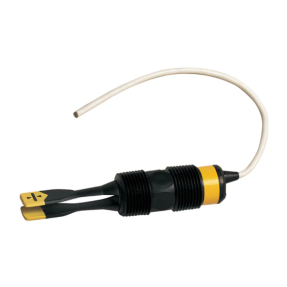
SPECIFICATIONS (optic) Step Two Optic Leak Detection Switch (LVF‐210A series): The Optic Leak Detector use principles of optical refraction to detect the presence or absence of fluid. A pulsed infrared light beam is internally generated by a light emitting diode and aimed at the slanted optical tip of the sensor. If the tip is dry, the light beam bounces at a 90 degree angle to a receiving photo transistor, indicating a dry condition. If the tip is immersed in liquid, the light beam will refract out into the liquid instead of being reflected to the photo transistor, indicating a wet condition. The LVF‐210A series is designed as a leak detection switch. The switch should be installed in applications ... - Page 9 SPECIFICATIONS (optic) Step Two LVF‐210A Series Specifications: Sensor material: ‐210A/‐212A: PP Cable jacket mat’l: ‐210A/‐212A: PP ‐211A/‐213A: PFA ‐211A/‐213A: PFA Configurations: Part Material Material Cable side Length Sensor side Number (body) (cable) LVF‐210A‐R Short (3”) Polypropylene Polypropylene (3/4” NPT) (3/4” NPT) LVF‐210A‐G‐R Short (3”) Polypropylene Polypropylene (3/4” R) (3/4” R) LVF‐211A‐R Short (3”) PFA PFA (3/4” NPT) (3/4” NPT) LVF‐211A‐G‐R Short (3”) ...
- Page 10 SPECIFICATIONS (capacitance) Step Two Capacitance Switch (LVC‐152 series): The capacitance level switch generates a pulse‐wave radio frequency signal from the capacitance electrode located in the sensing tip of each sensor. When liquid comes into contact with the sensing tip, the capacitance as measured by the sensor changes based on the dielectric constant ...
- Page 11 SPECIFICATIONS (capacitance) Step Two LVC‐152 Series Specifications: Dielectric range: >20 constants Sensor material: PP Conductive range: >100 miromhos Cable jacket mat’l: PP Configurations: Part Material Material Cable side Length Sensor side Number (body) (cable) LVC‐152‐R Long (4.5”) Polypropylene Polypropylene (3/4” NPT) (3/4” NPT) LVC‐152‐G‐R Long (4.5”) Polypropylene Polypropylene (3/4” R) (3/4” G) Note: all capacitance level switches are available with longer lengths cable of 25’ and 50’. For 25’ of cable, add (‐25) to the end of the part number and for 50’ of cable, add (‐50) to the end of the part number. Example, LVC‐152‐R‐25 will have 25’ of cable. Testing Tip: The LVC‐152 series sensor looks for changes in capacitance based upon the dielectric constant of the liquid. Although water has a high dielectric constant, the volume of a cup of water will not have enough change in capacitance to switch the sensor into a wet condition. One way to increase the capacitance for the cup of water is to dip your finger into the cup. The volume of water within your body will add to the water in the cup and will result in the sensor identifying a wet condition. ...
-
Page 12: Safety Precautions
SAFETY PRECAUTION Step Three About Manual: PLEASE READ THE ENTIRE MANUAL PRIOR TO INSTALLING OR USING THIS PRODUCT. This manual includes information on all models of Omega Engineering Powered Level Switches: LVU‐150 series, LTU‐101A series, LVF‐210A series and LVC‐152 series. Please refer to the part number located on the sensor label to verify the exact model which you have purchased. User’s Responsibility for Safety: OMEGA ENGINEERING manufactures a wide range of liquid level switches and technologies. While each of the these switches are designed to operate in a wide variety of applications, it is the user’s responsibility to select a switch model that is appropriate for the application, install it properly, perform tests of the installed system, and maintain all components. The failure to do so could result in ... -
Page 13: Make A Fail-Safe System
SAFETY PRECAUTION Step Three Make a Fail‐Safe System: Design a fail‐safe system that accommodates the possibility of switch and/or power failure. OMEGA ENGINEERING recommends the use of redundant backup systems and alarms in addition to the primary system. Adding a redundant high level float switch to the system is a cost effective means to prevent costly tank overflows. All of the powered level sensors have a single internal relay. The normally open (NO) or normally closed (NC) operation is user selected based on the desired system control. Always design a fail‐safe system that ... -
Page 14: Installation
15/16" wrench flat. This enables the user to select the sensor’s mounting orientation, installed outside of the tank in, or inside of the tank out. Top Wall Installation: The powered level switches may be installed through the top wall of a tank. Omega Engineering’s level track mounting system LVM‐10 series is an in‐tank fitting which enables users to install up to four OMEGA ENGINEERING sensors of any technology, to any depth, along the entire length of track. The LVM‐10 series may be installed through the top wall of any tank using a standard 2" NPT tank adapter. If no tank top installation is available, Omega Engineering's side mount bracket, LVM‐30, enables the LVM‐10 series to be installed directly to the side wall of a tank. Do not use the PFA bodied sensors with LVM‐10 series. Omega Engineering’s LVM‐50 series level track mounting system is an in‐tank fitting which enables users to install one OMEGA ENGINEERING sensor, of any technology, to a specific depth. The Omega Engineering sensor may be installed onto the 3/4" NPT adapter at the end of the LVM‐50 series. The LVM‐50 series may be installed through the top wall of any tank using a standard 2" NPT tank adapter. Omega Engineering's side mount bracket, model LVM‐30, may also be used if top wall installation is not available. 14 ... -
Page 15: Electrical
With a 20 gauge wire stripper, remove the last 1/4" of the colored insulation from the signal wires. Signal Outputs (Current sensing): The standard method used by Omega Engineering controllers; this technology uses only two wires (Red and Black). The sensor draws 5 mA when it is dry (8mA with LTU‐101A ... -
Page 16: Wiring
WIRING Step Six Wiring to a OMEGA ENGINEERING Controller LVCN‐120 Series Controller (4 or 20 mA output): LVCN‐100 Series Controller (4 or 20 mA output): LVCN‐120 Shown LVCN‐20 shown Switching Inductive Loads: The use of suppressors (snubbers) is strongly recommended when switching inductive loads to prevent disrupting the microprocessor’s operation. The suppressors also prolong the life of the relay contacts. Suppression can be obtained with a catch diode for DC circuits and a resistor‐capacitor (RC) for AC circuits. Catch Diode Always use stepper relays between the sensor and external loads. For DC circuits use a catch diode such as 1N4148, shown on left. Refer to the following circuits for RC network assembly and installation: Choose R and C as follows: R: 0.5 to 1 Ohms for each volt across the contacts C: 0.5 to 1 μF for each amp through closed contacts Notes: 1. Use capacitors rated for 250 VAC. ... -
Page 17: Wiring The Relay Output
WIRING (continued) Step Six Wiring the Relay Output: The sensor requires 12 ‐ 36 VDC (30 VDC max. for LTU‐101A series) power to operate the sensor and switch the relay. All illustrations below identify a Dry switch state as the normal position of the relay. ... -
Page 18: Wiring As A P-Channel Or N-Channel Output
WIRING (continued) Step Six Wiring as a P‐Channel or N‐Channel output: The sensor can be substituted for either a P‐Channel (PNP, sourcing) output or a N‐Channel (NPN, sinking) output. Normally Open DC Load as a P‐Channel Output: Normally Closed DC Load as a P‐Channel Output: The Red wire connects to Positive (+) of the power The Black wire connects to Positive (+) of the power supply ... -
Page 19: Maintenance
MAINTENANCE Step Seven General: The powered level switch requires no periodic maintenance except cleaning as required. It is the responsibility of the user to determine the appropriate maintenance schedule, based on the specific characteristics of the application liquids. Cleaning procedure: 1. Power: Make sure that all power to the switch, controller and/or power supply is disconnected. 2. Switch removal: In all through‐wall installations, make sure that the tank is drained well below the sensor prior to removal. Carefully, remove the sensor from the installation. ... -
Page 20: Testing The Installation
MAINTENANCE (continued) Step Seven Testing the installation: 1. Power: Turn on power to the controller and/or power supply. 2. Immersing the switch: Immerse the sensing tip in its application liquid, by filling the tank up to the switches point of actuation. An alternate method is to hold a cup filled with liquid up to the switch's tip. 3. Test: With the switch being fluctuated between wet and dry states, the switch indicator light in the controller should turn on and off. If the controller doesn't have an input indicator, use a voltmeter or ... - Page 21 21 ...
- Page 22 22 ...