
Related Manuals for Teledyne Triton FH Series


Summary of Contents for Teledyne Triton FH Series
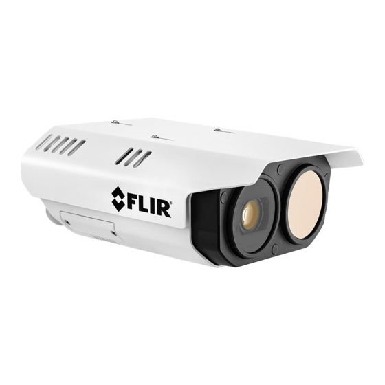
- Page 1 Installation and User Guide Triton™ FH-Series Camera 427-0102-00-10 - Revision 110 - November 2021 This document does not contain any export-controlled information.
- Page 2 © 2021 Teledyne FLIR LLC All rights reserved worldwide. No parts of this manual, in whole or in part, may be copied, photocopied, translated, or transmitted to any electronic medium or machine readable form without the prior written permission of Teledyne FLIR LLC.
- Page 3 Product Registration and Warranty Information Register your Product with Teledyne FLIR at https://customer.flir.com. For warranty information, see https://www.teledyneflir.com/support-center/warranty/security/flir-security- product-warranties/. 427-0102-00-10 - Revision 110 - November 2021 This document does not contain any export-controlled information.
-
Page 4: Table Of Contents
Table of Contents 1. Camera Overview ........................1 Accessing Product Information from the Teledyne FLIR Website ........2 Camera Dimensions ......................3 Camera Specifications ......................4 2. Installation ........................... 7 Supplied Components ......................8 Site Preparation ........................8 Supplying Power to the Camera ..................9 Additional Connections ...................... - Page 5 Table of Contents Users Page ........................42 Alarm Page ........................43 4.4.1 Modifying or Defining Rule Triggers ..............44 4.4.2 Modifying or Defining Rule Actions ..............45 Audio Page ........................46 I/O Devices Page ....................... 47 Messaging Page ........................ 49 Heaters &...
-
Page 6: Camera Overview
IP network using H.265, H.264, and MJPEG encoding, and provides analog video output. Camera Overview If help is needed during the installation process, contact the local Teledyne FLIR service representative or call the support number that appears on the product's page at https://support.flir.com/. All installers and integrators are encouraged to take advantage of the training offered by Teledyne FLIR;... -
Page 7: Accessing Product Information From The Teledyne Flir Website
Teledyne FLIR website. To access product information from the Teledyne FLIR website: 1. Open https://www.teledyneflir.com/browse/security/thermal-security-cameras/. Thermal Security Cameras Page on the Teledyne FLIR Website 2. Find and click the appropriate model, Triton™ FH-Series ID or R. The product details page appears. -
Page 8: Camera Dimensions
Camera Overview Product Support Page (FH-Series ID) 5. Select the relevant tab. For example, to download the DNA tool, open the Downloads tab. 6. To download the resource, click the corresponding Download link. Camera Dimensions The Triton FH-Series camera’s dimensions are (with sunshield): 427-0102-00-10 - Revision 110 - November 2021 This document does not contain any export-controlled information. -
Page 9: Camera Specifications
Camera Overview Camera Specifications FH-3xx models: 320x256 Array Format (NTSC) FH-6xx models: 640x512 Detector Type Long-life, uncooled VOx microbolometer Pixel Pitch 17 µm NTSC: 30 Hz or PAL: 25 Hz - user switchable Thermal Frame Rate < 9 Hz available Model Focal Length 69°... - Page 10 Camera Overview Target below 100°C (212°F): ± 5°C (±9°F) accuracy Target below 150°C (302°F): ± 5% accuracy Measurement Temperature Target above 150°C (302°F): ± 15% accuracy Accuracy Measurement (R Measured at 25°C ambient temperature. Inaccuracy can be greater at extreme temperatures.
- Page 11 User credentials with policy enforcement Digest authentication Specifications are subject to change without notice. For the most up-to-date specs, see the product's web page on the Teledyne FLIR website. 427-0102-00-10 - Revision 110 - November 2021 This document does not contain any export-controlled information.
-
Page 12: Installation
Supplying Power to the Camera · Additional Connections To install the camera, Teledyne FLIR recommends connecting the camera on a bench or in a lab and configuring it for networking before mounting and aiming it: Connect the Camera Configure for Networking... -
Page 13: Supplied Components
Supplied Components The Triton FH-Series camera kit includes these items: Teledyne FLIR ships the cameras with watertight cable glands and seal plugs attached to the rear cable ingress holes. In addition, the camera kit includes a bag with the following parts: ·... -
Page 14: Supplying Power To The Camera
12 VDC (±10%) · 24 VDC (±10%) · 24 VAC (±10%)—for example, Teledyne FLIR part number 4124857 · PoE IEEE 802.3bt 50W class 6 or 70W class 8 427-0102-00-10 - Revision 110 - November 2021 This document does not contain any export-controlled information. -
Page 15: Additional Connections
Installation Teledyne FLIR recommends using PoE 70W class 8 or 24V AC / DC. Other power sources limit low- temperature operation: PoE 50W class 6 PoE 70W class 8 Lowest operating -20°C -40°C -40°C -40°C temperature Cold start • •... -
Page 16: Connect The Camera
Guide. Connect the Camera Teledyne FLIR recommends connecting the camera on a bench or in a lab and configuring it for networking before mounting and aiming it. The camera's interfaces and connections are inside the camera body. A microSD card slot and reset / default button are located on a panel on the side of the camera. - Page 17 Installation Important Use a preformatted microSD card, or format it using the camera's web page or a PC. You can configure onboard storage or other storage on the edge (SoE) using FLIR UVMS, an approved third-party VMS, or another ONVIF-compliant client. For more information about using the camera's web page to format a microSD card, see Recording Page.
- Page 18 Installation Connection Description Attach a Cat 6 cable from the network switch to the RJ45 connection for a 100/1000 Mbps Ethernet and PoE connection. (56V 1.6A) A solid green LED indicates an active connection. A flashing orange LED PoE 802.3bt indicates data traffic between the camera and the network.
-
Page 19: Configure For Networking
• Notes · Teledyne FLIR recommends using the DNA tool to discover the camera on the network (version 2.3.0.20 or higher). It does not require a license to use and is a free download from the product's web page on the Teledyne FLIR website. - Page 20 Installation If the admin user password has been changed, you need to authenticate the camera. In the DNA Discover List, right-click the camera and select Login. In the DNA - Login window, type the password for the admin user. If you do not know the admin user password, contact the person who configured the camera's users and passwords.
-
Page 21: Mount The Camera
To ensure watertight seals, the cable outer diameter must be between 0.23"-0.29". If you are using other, non-standard cable diameters, you might need to locate or fabricate an insert to fit the cable. Teledyne FLIR does not provide cable gland inserts other than those supplied with the camera. -
Page 22: Aim The Camera
Installation Carefully loosen and remove the gland nuts. Remove the appropriate number of cable gland seal plugs. However, make sure seal plugs are securely in place for all unused gland seal holes. Route the cables through the gland seals before terminating and connecting them. -
Page 23: Additional Configuration
Installation 2.12 Additional Configuration Depending on how you are installing and using the Triton FH-Series camera, and the network and VMS to which it is connected, initial configuration can also consist of enabling, disabling, or configuring the following settings using the camera's web page: Settings User Role ·... -
Page 24: Operation
Discover List. The DNA tool does not require a license to use and version 2.3.0.20 or higher is a free download from the product's web page on the Teledyne FLIR website. Download the DNA tool; unzip the file; and then double-click to run the tool (DNA.exe). -
Page 25: Making Changes To Settings
Operation View Settings Home Page - FH-xxx R models - Users Assigned the Admin or Expert Role Visible Video Images Selected - Default Settings System Settings Users assigned the admin or expert role can click System Settings to configure the camera. For more information, see Configuration. - Page 26 Operation Whenever possible, Teledyne FLIR recommends testing new settings before saving them because saving changes overwrites the previously saved settings. View Settings When you make a change to most View Settings, the Reset and Save buttons become enabled. For some View Settings, the camera immediately applies the changes, but does not save them;...
-
Page 27: Video Page
On the camera web page and in the camera's cloud web application, the live video is not an actual video stream. Changes to stream settings might not affect the live video. Before saving changes, Teledyne FLIR recommends checking them using a FLIR UVMS, client program, or third- party ONVIF system. - Page 28 Operation · Rate Control: o CBR (constant bit rate)—The Bit Rate parameter defines the target bit rate; the camera attempts to keep the video at or near the target bit rate. o VBR (variable bit rate)—The Bit Rate parameter defines the average bit rate. ·...
-
Page 29: Visible Page
Operation Visible Page You can adjust the following visible video settings: · Brightness · Contrast (Max Gain) · · Saturation · Sharpness · Focus · Autofocus Push—Activates a one-time autofocus. Advanced Settings · Night Mode—Set the visible video to: o Color (day mode) o B/W (night mode) o Auto (default)—Automatically switches the visible video mode according to light level. - Page 30 Operation increase the dWDR setting as the level of scene contrast increases. To enable and configure Shutter (True) WDR, see Exposure Mode below. · White Balance—Set according to operating environment: o Auto (default)—Computes the white balance value output using color information from the entire screen.
- Page 31 Minimum Shutter Speed—Specify the slowest shutter speed based on the amount of light in the scene, speed of moving objects, and noise. If the scene includes fast-moving objects, Teledyne FLIR recommends specifying a minimum shutter speed faster than 1/25 or 1/30 seconds.
- Page 32 Operation Maximum Shutter Speed - Auto Shutter Mode NTSC 1/200 1/2000 1/12500 1/200 1/2000 1/12500 1/250 1/2500 1/16000 1/250 1/2500 1/16000 1/400 1/4000 1/20000 1/400 1/4000 1/20000 1/500 1/5000 1/25000 1/500 1/5000 1/25000 1/800 1/8000 1/32000 1/800 1/8000 1/32000 o Shutter Priority—Specify a fixed shutter speed. o Flickerless (default)—Eliminates flicker caused by fluorescent lighting in the screening area.
-
Page 33: Thermal Page
Be aware that, when conditions change, you might need to adjust the parameters again. Teledyne FLIR recommends knowing how to restore the factory default settings (see Firmware &... - Page 34 Operation Defining a custom AGC ROI To change the size of the ROI: Hover over the To move the entire ROI: Hover over the ROI, and handle in the bottom-right corner of the ROI, then click and drag it. and then click and drag it. AGC Image Settings In some cases, changing the AGC image settings can provide a better image, depending on personal preferences, display devices, and so on.
-
Page 35: Illumination Page
Operation Illumination Page When external illumination is enabled, the Illumination page is available. Users assigned the admin or expert role can enable external illumination on the Firmware & Info Page. By default, infrared illumination is set to Auto; when the scene becomes dark enough, the visible camera video changes from day mode (color) to night mode (black and white) and turns on the external infrared illumination, using the ALARM OUT 2 connection... -
Page 36: Radiometry Page (R Models)
FH-Series R models detect, measure, and monitor surface temperatures. Because using a thermal camera for reasonably accurate and precise temperature measurements requires at least a minimum level of expertise in thermography, Teledyne FLIR recommends training. The Infrared Training Center (http://www.infraredtraining.com/) offers training (including online training) and certification in all aspects of thermography. - Page 37 Operation Enable the camera's radiometry features and then select the temperature units (Kelvin, Celsius, or Fahrenheit). Vehicle Detection Filter The vehicle detection filter prevents vehicles from triggering false radiometric alarms. It requires vehicle classification to be enabled on one or more loitering regions on the thermal video. Defining loitering regions makes sure the camera’s video analytics continue to track moving vehicles that become stationary.
-
Page 38: Video Analytics Page
Operation · Condition—You can select whether a detected temperature Above, Below, or Matches the alarm threshold value triggers an alarm. · Threshold—Specify a temperature value in degrees Kelvin, Celsius, or Fahrenheit, depending on the setting above. · Hysteresis—Specify the number of degrees above or below the Threshold within which the camera does not clear the alarm. - Page 39 Operation · For both the visible and thermal video, create and configure tripwires, intrusion detection or loitering regions, and masking regions. By default, tripwires or regions have not been defined, and alarm rules are disabled. · Enable and configure the analytics tracking overlay. The camera immediately applies and saves changes to settings on the Video Analytics page, affecting the live video images, video streams, and analog video output.
-
Page 40: Check The Analytics Calibration
Operation To configure the camera's video analytics: 1. Make sure the camera is mounted in its final location and properly aimed. 2. On the Georeference Page, specify the camera's installation height, tilt angle, and roll angle. 3. Enable the analytics overlay. Check the Analytics Calibration. -
Page 41: Create Analytics Regions
Operation 3.10.2 Create Analytics Regions Create separate analytics regions for the visible video and for the thermal video; for example, to define separate regions according to the time of day. You can also create a masking region; a region that does not generate intrusion alarms. - Page 42 Operation Tips · Remember to create analytics regions for both the visible and thermal video images, if desired. · To cancel creating a region, press Esc. · To modify the settings for or to delete an existing region, click the region either in the region list or in the live video image.
-
Page 43: Osd Page
Operation Note The camera provides intrusion detection masking, not privacy masking. Analytics are disabled for masking regions, and the camera does not generate alarms. However, the region itself appears in the video image. To establish dependency between two regions: 1. Select a region and then click Set Dependency. 2. -
Page 44: Georeference Page
(below horizontal), the tilt angle leaning to the right, the roll angle from North. is negative. is negative. Teledyne FLIR recommends mounting the camera with a 0º installation roll angle. For accurate video analytics, mount the camera with an installation roll angle within ±5º. -
Page 45: Configuration
Configuration Configuration Users assigned the admin or expert role can click System Settings on the View Settings Home Page access the following configuration pages: · · Network Page Cyber Page · · Date & Time Page ONVIF Page · · Users Page Map Page ·... -
Page 46: Date & Time Page
Configuration Caution After changing the camera's IP address, the PC you are using to access the camera's web page might no longer be on the same network as the camera and can no longer access the camera's web page. To access the camera web page again, change the PC's IP address to be on the same network as the camera. -
Page 47: Users Page
Configuration Email notifications and other camera features require configuring the camera’s system time to be the current time. You can configure email notifications on the Messaging Page. Users Page Only users assigned the admin role can add users and change or set all passwords. Users assigned the expert role only see the user currently logged in, and cannot add, edit, or delete a user. -
Page 48: Alarm Page
Configuration Add User Edit User To keep the existing password, leave the password fields empty. Delete User Alarm Page You can define camera alarms to be triggered by the following: · The camera's onboard video analytics · The camera's radiometry (R models) ·... -
Page 49: Modifying Or Defining Rule Triggers
Configuration · 1. Video analytics change output state—The camera's video analytics trigger a change to the state of an local alarm output connector. If the idle state of the connector is Closed, the alarm changes the state to Open. Likewise, if the idle state is Open, the alarm changes the state to Closed. For information about configuring the idle state of the camera's local I/O connector pins, see Input/Output (I/O) -
Page 50: Modifying Or Defining Rule Actions
Configuration Local Triggers a. On the Input/Output (I/O) Page, make sure local I/O Local—This camera's connectors have been properly configured. local I/O connections b. Select one or more local I/O connections that trigger this rule's action. Keep in mind that, when enabled, the trigger this rule's action. -
Page 51: Audio Page
Configuration To modify or define alarm rule actions: 1. For the alarm rule you are modifying or defining, select an action type: Action Type Under I/O List, select Local or External. Local—This rule changes the state of local I/O connectors. a. -
Page 52: I/O Devices Page
Configuration The On/Off buttons affect all audio input and output. For example, turning audio off immediately turns off all camera audio. Audio In When audio is On, the following audio input settings appear: · Gain—You can adjust the audio input gain from 0-100 percent. The default is 90 percent. ·... - Page 53 Configuration You can configure the following for the device managing the external I/O connections are available: · Enabled or Disabled · Device IP address and port · Input and output base addresses · The number of input and output pins the device manages For each pin, the following information appears and you can confgure: ·...
-
Page 54: Messaging Page
Configuration Messaging Page an action for an alarm rule, the camera can send a notification email using the mail server settings you can configure on the Messaging page. Specify the settings for the SMTP server in the appropriate fields. Settings include the SMTP server's IP address;... -
Page 55: Cyber Page
Configuration Select the units of temperature that appear on the page: Celsius, Fahrenheit, or Kelvin. On R models, note that this setting is independent of the Units setting on the Radiometry Page (R models). To manually activate defogging or deicing on one of the camera's sensors or on both of them: 1. -
Page 56: Certificates
Configuration 4.9.1 Certificates Before you can enable TLS/HTTPS or 802.1X, you need to generate or upload a valid certificate. You can use the camera's web page to generate a self-signed certificate; upload a self-signed certificate; or upload a certificate signed by a third-party. If you do not know how to configure these settings, contact your network administrator. -
Page 57: Tls / Https
Configuration 2. If you are uploading a self-signed certificate, under Public Key and then under Private Key: a. Click b. Select the appropriate key file. c. Click If you are uploading a third-party CA signed certificate, select and upload the Public Key, Private Key, and CA Certificate. -
Page 58: Services
Configuration 4.9.4 Services Enable or disable digest authentication for the FLIR CGI control interface. The default setting is On (enabled). Enable or disable RTSP authentication. The default setting is On (enabled). When disabled, accessing the camera's video streams does not require authentication. Firewall Settings For enhanced security, the camera has a firewall that is disabled by default. -
Page 59: Onvif Page
Configuration To define specific IP addresses that can access the camera, click Allow. The camera will deny access to all other IP addresses. To define specific IP addresses that cannot access the camera, click Deny. The camera will allow access to all other IP addresses. - Page 60 Configuration To upload a reference map image and calibrate the radar to the map: 1. Using an online map or GPS service such as Google Maps, download a reference map image. For example, if you use Google Maps or another online map, you can take a screenshot of a satellite view of the radar’s detection range.
-
Page 61: Boresight Page
Configuration 4. Click Accept. If a map does not successfully upload, try again. Try changing the quality or compression of the map image. Higher quality or lower compression increases the map file size. Right-Click on Map What’s here? in Google Maps 5. - Page 62 Configuration Tips · With the lenses physically separated, even slightly, the most accurate alignment is at a specific distance from the camera. The alignment shifts slightly for objects closer or further away from that distance. When making the fine-tuning boresight adjustments, align the images on objects that are the same distance from the camera.
- Page 63 Configuration 5. Hover over the same point in the other image, right-click, and then click Add Point. 6. Add more pairs of calibration points by repeating the previous steps. 7. Click Calibrate. 8. The camera aligns the images according to calibrations points by adjusting each imager's zoom, offsets, and so on.
- Page 64 Configuration Advanced Settings Important For accurate video analytics, the VFOVs must be properly aligned. Teledyne FLIR recommends setting the vertical FOV of visible image slightly wider than the thermal image vertical FOV of thermal. If you select Overlap Thermal Image, you can specify the opacity of the thermal image over the visible image.
-
Page 65: Scheduler Page
Configuration 4.13 Scheduler Page You can define one-time or recurring tasks, including their start and stop times. For example, you can: · Enable the camera's video analytics during certain times of the day. · Schedule periodic uploads of snapshots of live video images to an FTP/SFTP server. Note You cannot use the scheduler to define a task that records live video. - Page 66 Configuration Predefined Actions Send Status Sends an email with information about the camera's status, according to the settings on the Messaging Page. Email a. Select whether the task disables (off) or enables (on) alarm rules. Switch Alarm Rules b. Select the alarm rules the task affects, according to rule ID number. To determine the rule ID, check the Alarm Page.
-
Page 67: Recording Page
Configuration Enable or disable a task by clicking Enabled or Disabled. To delete a task, click the corresponding trash icon 4.14 Recording Page If a microSD card has been properly inserted in the camera's microSD slot, you can format it on the Recording page. - Page 68 Configuration Name Specify a unique, friendly name for the camera, using only alphanumeric characters. The default name for the camera is the camera model followed by the camera’s serial number. To upgrade the camera's firmware: 1. Make sure the camera has been recently rebooted. 2.
- Page 69 Configuration Caution After confirming a reset, do not click on the camera web page. Wait until the camera reboots and the login screen appears. Then, according to the instructions in Accessing the Camera, log back in to the camera web page using the camera's default admin user. To reboot the camera and reset the camera to previously saved settings, click Reboot, and then confirm.
- Page 70 Configuration Analog Video Source—Specify the source for the camera's T/V analog video output: · None—Disables the camera's T/V analog video output. · Visible · Thermal External Illumination Setting—Enables the View Settings Illumination Page, where you can disable and enable automatic external IR illumination. 427-0102-00-10 - Revision 110 - November 2021 This document does not contain any export-controlled information.
-
Page 71: Maintenance And Troubleshooting Tips
By default, the camera broadcasts a discovery packet twice per second. Use version 2.3.0.20 or higher of the Teledyne FLIR Discovery Network Assistant (DNA) tool or a packet sniffer utility such as Wireshark and confirm the packets are being received by the PC from the camera. - Page 72 If a fuse was used, be sure the fuse is not blown. If the camera still does not produce an image, contact the Teledyne FLIR dealer or reseller who provided the camera, or contact Teledyne FLIR directly.
- Page 73 Once installed, the camera might point directly east or west, which can cause the sun to be in the field of view during certain portions of the day. Teledyne FLIR does not recommend intentionally pointing the camera at the sun. The sun can introduce image artifacts that the imager eventually corrects. However, recovery can take some time.
-
Page 74: Appendix
For the full procedure, see the ioi HTML Edition Units User Guide; you can download it from the product’s web page on the Teledyne FLIR website. For information about using FLIR UVMS to bind the camera to the PTZ tracker, see the UVMS documentation. - Page 75 Appendix 5. On the Camera > Type & Model screen, make sure that the Camera Type selected is Pan/Tilt/Zoom (PTZ). 6. Click Start PTZ Setup. The Detection and Tracking screen appears. 427-0102-00-10 - Revision 110 - November 2021 This document does not contain any export-controlled information.
- Page 76 Appendix 7. Select Detection from another camera with Automatic PTZ tracking. Click Next. The Calibration screen appears. 8. Follow the on-screen instructions. When the PTZ camera has been calibrated, click Next. The PTZ Synchronization screen appears. 9. On the PTZ Synchronization screen, perform Step 3: PTZ Synchronization with Fixed Cameras of Using the PTZ Camera Definition Wizard in the ioi HTML Edition Units User Guide.
- Page 77 Appendix For more information about defining correlation points, in the ioi HTML Edition Units User Guide, see To set correlation points in a preset. 12. Click Next and then click Finish. 13. Return to Live View and click Arm. 14. On the Video Analytics Page, enable the FH-Series camera's analytics.
- Page 78 Americas 27700 SW Parkway Ave. Wilsonville, OR 97070 6769 Hollister Ave Goleta, CA 93117 Support: https://support.flir.com/ Document: 427-0102-00-10 Revision: 110 Date: November 2021 This document does not contain any export-controlled information.