Table of Contents

Related Manuals for Teledyne Genie Nano-5G Series


Summary of Contents for Teledyne Genie Nano-5G Series
- Page 1 ™ Genie Nano-5G Series Camera User’s Manual 5 Gb GigE Vision – Monochrome & Color Area Scan sensors | cameras | frame grabbers | processors | software | vision solutions November 25, 2022 Rev: 0010 P/N: G5-G00M-USR00 www.teledynedalsa.com...
- Page 2 All information provided in this manual is believed to be accurate and reliable. No responsibility is assumed by Teledyne DALSA for its use. Teledyne DALSA reserves the right to make changes to this information without notice. Reproduction of this manual in whole or in part, by any means, is prohibited without prior permission having been obtained from Teledyne DALSA.
-
Page 3: Table Of Contents
Contents GENIE NANO-5G SERIES OVERVIEW ______________________________ 8 ....................8 ESCRIPTION GigE with TurboDrive ................9 Genie Nano-5G Overview ..............10 Camera Firmware ................. 10 ................... 11 ODEL UMBERS Monochrome Cameras ................11 Color Cameras ..................11 Optional Hardware Accessories .............. 12 Optional Cable Accessories .............. - Page 4 ON-SEMI SENSOR MODELS _____________________________________ 31 : M4500 ................32 PECIFICATIONS : C4500 ................33 PECIFICATIONS : M5420 ................34 PECIFICATIONS : C5420 ................35 PECIFICATIONS : M8100 ................36 PECIFICATIONS : C8100 ................38 PECIFICATIONS .............. 40 IRMWARE ILES FOR ODELS Monochrome Camera Firmware ..............
- Page 5 ................63 ENSOR ONTROL ATEGORY Sensor Control Feature Descriptions ............63 Offset/Gain Control Details (Sony sensors) ..........66 Sony Sensors Gain Stage Diagram ..............66 Bayer Mosaic Pattern ................67 Exposure Alignment: Overview .............. 67 Synchronous Exposure Alignment ..............67 Sensor Exposure Timing ................
- Page 6 Cycling Reset Timing Details ..............113 Case 1: Cycling with Internal Synchronous Increment ........113 Case 2: Cycling with External Asynchronous Increment ......... 114 Using Cycling Presets with Output Controls ..........115 Feature Settings for this Example ............... 115 Cycling Mode Constraints with a changing ROI ........116 Specifics Concerning Sony Sensor Models ............
- Page 7 GigE Vision Transport Layer Feature Descriptions ........156 Defaults for devicePacketResendBufferSize ..........161 ............162 ISION ONTROL ATEGORY Teledyne DALSA TurboDrive ..............162 ..............163 CCESS ONTROL ATEGORY File Access Control Feature Descriptions ..........163 Updating Firmware via File Access in CamExpert ........165 Overview of the deviceUserBuffer Feature ..........
- Page 8 Examples of Available Lenses for High Resolution Models ....... 193 Additional Lens Parameters (application specific) ........194 ................194 PTICAL ONSIDERATIONS Illumination ..................194 Light Sources ..................195 IR Cut-off Filters ................195 Nano-5G C-Mount Models with Built-in IR Cut-off Filters ........ 195 Guidelines for Choosing IR Cut-off Filters .............
- Page 9 ADDENDA _________________________________________________ 223 I/O C ) ........223 ONNECTOR INOUT ETAILS PECIAL RDER ............224 SING THE PECIAL RDER ERIAL Enable the Virtual Serial Port Driver............224 Automatic Windows Driver Installation ............225 Selecting Serial Port Parameters ..............225 Serial Port Control Category ............... 226 GigE Vision Transport Layer Feature Descriptions ..........
-
Page 10: Genie Nano-5G Series Overview
Genie Nano-5G Series Overview Description The Genie Nano-5G series, a member of the Genie camera family, provides a new series of affordable easy to use digital cameras specifically engineered for industrial imaging applications requiring improved network integration. Genie Nano-5G cameras feature the industry's latest leading sensors such as the Sony Pregius series of global shutter active pixel-type CMOS image sensors, as well as On-Semi sensors. -
Page 11: Gige With Turbodrive
Refer to TurboDrive Primer on the Teledyne DALSA web site for more details. Note: The specification listed for Maximum Sustained Frame Rate Output (with TurboDrive v2) is limited by the Genie Nano-5G Architecture into the TurboDrive Engine to ~950MB/sec sustained using 1500 Byte Packet Size. -
Page 12: Genie Nano-5G Overview
Teledyne DALSA Genie Nano-5G camera firmware contains open source software provided under different open source software licenses. More information about these open source licenses can be found in the documentation that accompanies the firmware, which is available on the Teledyne DALSA website at www.teledynedalsa.com... -
Page 13: Model Part Numbers
With IR cut-off filter Nano-5G-C4500 On-Semi 20M M42-mount G5-GC31-C4505 4504 x 4504 (XGS20000) On-Semi 30M Nano-5G-C5420 M42-mount G5-GC31-C5425 5420 x 5420 (XGS30000) On-Semi 45M Nano-5G-C8100 M42-mount G5-GC31-C8105 8192 x 5420 (XGS45000) Nano-5G Series GigE Vision Camera Genie Nano-5G Series Overview • 11... -
Page 14: Optional Hardware Accessories
• and a 2 meter I/O Breakout Cable (Euroblock) See section Components Express Right-Angle Cable Assemblies Alysium-Tech “Extreme Rating” HiFlex Ethernet Cable for additional cabling options available directly from our preferred cable sources. 12 • Genie Nano-5G Series Overview Nano-5G Series GigE Vision Camera... -
Page 15: Software Requirements
GenICam™ specification. For more information see www.genicam.org. The Teledyne DALSA GigE Vision Module provides a license free development platform for Teledyne DALSA GigE hardware or Sapera vision applications. Additionally supported are Sapera GigE Vision applications for third party hardware with the purchase of a GigE Vision Module license, or the Sapera processing SDK with a valid license. -
Page 16: Genie Nano-5G Specifications
Genie Nano-5G Specifications The Nano-5G common specifications listed first are followed by model specific tables of functional features and timing details. Common Specifications Camera Controls Synchronization Modes Free running, External triggered, Software trigger through Ethernet or IEEE 1588 Precision Time Protocol (PTP) Exposure Control Internal –... - Page 17 Back Focal Distance 17.52 mm (C-mount models) 12 mm (M42-mount models) Mechanical Interface Camera (L x H x W) Medium body size: see Mechanical Specifications 42.6 mm x 44 mm x 59 mm (with C-mount) 32.3 mm x 44 mm x 59 mm (without C-mount) XL body size: 41 mm x 59 mm x 59 mm Mass (approximate value due to...
-
Page 18: Sensor Cosmetic Specifications
Sensor Cosmetic Specifications After Factory Calibration and/or Corrections are Applied (if applicable — dependent on sensor) Blemish Specifications Maximum Number of Blemish Description Defects Hot/Dead Pixel defects Typical 0.0025% Any pixel that deviates by ±20% from the average of Max 0.005% neighboring pixels at 50% saturation including pixel stuck at 0 and maximum saturated value. -
Page 19: Emi, Shock And Vibration Certifications
EMI, Shock and Vibration Certifications Compliance Directives Standards ID Overview EN61000-4-2: 2008 Electrostatic discharge immunity test EN61000-4-3: 2006 A1 : 2007 A2 : Radiated, radio-frequency, electromagnetic field 2010 immunity test EN61000-4-4: 2004 Electrical fast transient/burst immunity test EN61000-4-5: 2005 Surge immunity Immunity to conducted disturbances, induced by EN61000-4-6: 2008 radio-frequency fields... -
Page 20: Mean Time Between Failure (Mtbf)
Mean Time between Failure (MTBF) The analysis was carried out for operating temperatures varying from -20 to 100ºC. The following table presents the predicted MTBF and failure rate values. MTBF Temperature Failure Rate °C (Failure/10 hours) Hours Years 12642225 1443 0.0791 6489293 0.154.1... - Page 21 It is recommended to test network device performance since certain devices may not achieve acceptable results in actual operation (depending on the device manufacturer’s implementation). In general, it is always recommended to use the latest device drivers provided by the manufacturer. For example, the Intel X550 network adapter achieves superior performance compared to some other manufacturer’s comparable devices.
-
Page 22: Sony Sensor Models
Sony Sensor Models Specifications, firmware files spectral response curves for Genie Nano-5G cameras utilizing Sony sensors (monochrome and color) are described in the following sections. Note: The specification listed for Maximum Sustained Frame Rate Output (with TurboDrive v2) is limited by the Genie Nano-5G Architecture into the TurboDrive Engine to ~950 MB/sec sustained using 1500 Byte Packet Size. -
Page 23: Specifications: M2050
Specifications: M2050 Supported Features Nano-5G-M2050 Resolution 2064 x 1544 Sensor Sony IMX252 (3.2M) Pixel Size 3.45 µm x 3.45 µm Shutter type Full frame electronic global shutter function Firmware option Standard Design (factory) (Field programmable) 12-bit Design Full Well charge (firmware design dependent) 11ke (max) Sensitivity to Saturation 187 fps (8-bit) with Standard Design... -
Page 24: Specifications: C2050
Specifications: C2050 Supported Features Nano-5G-C2050 Resolution 2064 x 1544 Sensor Sony IMX252 (3.2M) Pixel Size 3.45 µm x 3.45 µm Shutter type Full frame electronic global shutter function Firmware option Standard Design (factory) (Field programmable) 12-bit Design Full Well charge (firmware design dependent) 11ke (max) Sensitivity to Saturation 187 fps (8-bit) with Standard Design... -
Page 25: Specifications: M2450
Specifications: M2450 Supported Features Nano-5G-M2450 Resolution 2464 x 2056 Sensor Sony IMX250 (5.1M) Pixel Size 3.45 µm x 3.45 µm Shutter type Full frame electronic global shutter function Standard Design (Factory) Firmware option (Field programmable) 12-bit Design Full Well charge (firmware design dependent) 10.7 ke (max) Sensitivity to Saturation 141 fps (8-bit) with Standard Design... -
Page 26: Specifications: C2450
Specifications: C2450 Supported Features Nano-5G-C2450 Resolution 2464 x 2056 Sensor Sony IMX250 (5.1M) Pixel Size 3.45 µm x 3.45 µm Shutter type Full frame electronic global shutter function Standard Design (Factory) Firmware option (Field programmable) 12-bit Design Full Well charge (firmware design dependent) 10.7ke (max) Sensitivity to Saturation 141 fps (8-bit) with Standard Design... -
Page 27: Specifications: M4060
Specifications: M4060 Supported Features Nano-5G-M4060 Resolution 4112 x 2176 Sensor Sony IMX255 (8.9M) Pixel Size 3.45 µm x 3.45 µm Shutter type Full frame electronic global shutter function Firmware option Standard Design (Factory) (Field programmable) 12-bit Design Full Well charge (firmware design dependent) 10.7ke (max) Sensitivity to Saturation Max. -
Page 28: Specifications: C4060
Specifications: C4060 Supported Features Nano-5G-C4060 Resolution 4112 x 2176 Sensor Sony IMX255 (8.9M) Pixel Size 3.45 µm x 3.45 µm Shutter type Full frame electronic global shutter function Firmware option Standard Design (Factory) (Field programmable) 12-bit Design Full Well charge (firmware design dependent) 10.7ke (max) Sensitivity to Saturation Max. -
Page 29: Specifications: M4040
Specifications: M4040 Supported Features Nano-5G-M4040 Resolution 4112 x 3008 Sensor Sony IMX253 (12M) Pixel Size 3.45 µm x 3.45 µm Shutter type Full frame electronic global shutter function Firmware option Standard Design (Factory) (Field programmable) 12-bit Design) Full Well charge (firmware design dependent) 10.6 ke (max) Sensitivity to Saturation 63.79 fps (8-bit) with Standard Design... -
Page 30: Specifications: C4040
Specifications: C4040 Supported Features Nano-5G-C4040 Resolution 4112 x 3008 Sensor Sony IMX253 (12M) Pixel Size 3.45 µm x 3.45 µm Shutter type Full frame electronic global shutter function Firmware option Standard Design (Factory) (Field programmable) 12-bit Design) Full Well charge (firmware design dependent) 10.6ke (max) Sensitivity to Saturation 63.79 fps (8-bit) with Standard Design... -
Page 31: Firmware Files For Sony Models
Firmware Files for Sony Models The latest firmware files for Sony Nano-5G models are available on the Teledyne DALSA support web site: http://www.teledynedalsa.com/imaging/support/downloads/firmware/ The firmware files for mono and color models are listed below. The xx denotes the current build number. -
Page 32: Spectral Response Curves For Sony Models
Spectral Response Curves for Sony Models Monochrome Models M2050 / M2450 / M4040 / M4060 Color Models C2050 / C2450 / C4040 / C4060 30 • Sony Sensor Models Nano-5G Series GigE Vision Camera... -
Page 33: On-Semi Sensor Models
On-Semi Sensor Models Specifications, firmware files spectral response curves for Genie Nano-5G cameras utilizing On- Semi sensors (monochrome and color) are described in the following sections. Nano-5G Series GigE Vision Camera On-Semi Sensor Models • 31... -
Page 34: Specifications: M4500
Specifications: M4500 Camera Models Nano-5G-M4500 Resolution 4504 x 4504 Sensor On-Semi XGS20000 Pixel Size 3.2 µm x 3.2 µm Shutter type Full frame electronic global shutter function Firmware option (Field programmable) Standard 8-bit Design (Factory) Full Well charge (firmware design dependent) 10 ke- (max) Sensitivity to Saturation Max. -
Page 35: Specifications: C4500
Specifications: C4500 Camera Models Nano-5G-C4500 Resolution 4504 x 4504 Sensor On-Semi XGS20000 Pixel Size 3.2 µm x 3.2 µm Shutter type Full frame electronic global shutter function Firmware option (Field programmable) Standard 8-bit Design (Factory) Full Well charge (firmware design dependent) 10 ke- (max) Sensitivity to Saturation Max. -
Page 36: Specifications: M5420
Specifications: M5420 Camera Models Nano-5G-M5420 Resolution 5420 x 5420 Sensor On-Semi XGS30000 Pixel Size 3.2 µm x 3.2 µm Shutter type Full frame electronic global shutter function Firmware option (Field programmable) Standard 8-bit Design (Factory) Full Well charge (firmware design dependent) 10k e- (max) Sensitivity to Saturation Max. -
Page 37: Specifications: C5420
Specifications: C5420 Camera Models Nano-5G-C5420 Resolution 5420 x 5420 Sensor On-Semi XGS30000 Pixel Size 3.2 µm x 3.2 µm Shutter type Full frame electronic global shutter function Firmware option (Field programmable) Standard 8-bit Design (Factory) Full Well charge (firmware design dependent) 10k e- (max) Sensitivity to Saturation Max. -
Page 38: Specifications: M8100
Specifications: M8100 Camera Models Nano-5G-M8100 Resolution 8192 x 5420 Sensor On-Semi XGS45000 Pixel Size 3.2 µm x 3.2 µm Shutter type Full frame electronic global shutter function Firmware option Standard 8-bit Design (Factory) (Field programmable) 12-bit Design Full Well charge (firmware design dependent) 10k e- (max) Sensitivity to Saturation Max. - Page 39 Camera Models Nano-5G-M8100 Synchronization via external trigger signal, Action Cameras synchronization Command or using PTP (IEE1588) modulo On-Board Image Memory 430 MB Output Dynamic Range (dB) 67.5 dB (Standard Design) SNR (dB) 39.6 dB Nano-5G Series GigE Vision Camera On-Semi Sensor Models • 37...
-
Page 40: Specifications: C8100
Specifications: C8100 Camera Models Nano-5G-C8100 Resolution 8192 x 5420 Sensor On-Semi XGS45000 Pixel Size 3.2 µm x 3.2 µm Shutter type Full frame electronic global shutter function Firmware option Standard 8-bit Design (Factory) (Field programmable) 12-bit Design Full Well charge (firmware design dependent) 10k e- (max) Sensitivity to Saturation Max. - Page 41 Camera Models Nano-5G-C8100 Output Dynamic Range (dB) 67.5 dB (Standard Design) SNR (dB) 39.6 dB Nano-5G Series GigE Vision Camera On-Semi Sensor Models • 39...
-
Page 42: Firmware Files For On-Semi Models
Firmware Files for On-Semi Models The latest firmware files for Nano-5G On-Semi models are available on the Teledyne DALSA support web site: http://www.teledynedalsa.com/imaging/support/downloads/firmware/ The firmware files for mono and color models are listed below. The xx denotes the current build number. -
Page 43: Spectral Response Curves For On-Semi Models
Spectral Response Curves for On-Semi Models The response curves describe the sensor, excluding lens and light source characteristics. Monochrome Models M4500 / M5420 / M8100 Color Models C4500 / C5420 / C8100 Nano-5G Series GigE Vision Camera On-Semi Sensor Models • 41... -
Page 44: Nano-5G Quick Start
If you are familiar with GigE Vision cameras, follow these steps to quickly install and acquire images with Genie Nano-5G and Sapera LT in a Windows OS system. If you are not familiar with Teledyne DALSA GigE Vision cameras go to Connecting the Genie Nano-5G Camera. -
Page 45: Connecting The Genie Nano-5G Camera
Refer to the Teledyne DALSA Network Imaging manual for additional information. Connect the Genie Nano-5G Camera Connecting a Genie Nano-5G to a network system is similar whether using the Teledyne DALSA Sapera LT package or a third party GigE Vision development package. -
Page 46: Connectors
See Ruggedized RJ45 Ethernet Cables for secure cables. • A 10 pin I/O connector for camera power, plus trigger, strobe and general I/O signals. The connector supports a retention latch, while the Nano-5G case supports thumbscrews. Teledyne DALSA provides optional cables (see Optional Hardware Accessories) •... -
Page 47: Led Indicators
LED Indicators The Genie Nano-5G has one multicolor LED to provide a simple visible indication of camera state, as described below. The Nano-5G Ethernet connector does not have indicator LEDs; the user should use the LED status on the Ethernet switch or computer NIC to observe networking status. Camera Status LED Indicator The camera is equipped with one LED to display its operational status. -
Page 48: Genie Nano-5G Ip Configuration Sequence
• Persistent IP (if enabled) • DHCP (if a DHCP server is present such as the Teledyne DALSA Smart DHCP server) • Link-Local Address (always enabled as default) The factory defaults for Nano-5G is Persistent IP disabled and DHCP enabled with LLA always enabled as per the GigE Vision specification. -
Page 49: Preventing Operational Faults Due To Esd
An Ethernet cable has no ground connection and a power supply’s 0 volt return line is not necessarily connected to earth ground. Teledyne DALSA has performed ESD testing on Nano-5G cameras using an 8 kilovolt ESD generator without any indication of damage to camera hardware (however the camera might reboot and reconnect to the application). -
Page 50: Using Nano-5G With Sapera Api
Nano, especially when on battery power. • Nano-5G also can connect through a Gigabit Ethernet switch. When using VLAN groups, the Nano-5G and controlling computer must be in the same group (refer to the Teledyne DALSA Network Imaging Package user’s manual). •... -
Page 51: Installation
Teledyne DALSA TurboDrive™ technology. Note that Nano-5G features may change when an older versions of Sapera LT is used. • Optional: If the Teledyne DALSA Sapera LT SDK package is not used, click to install the Genie Nano-5G firmware and user manuals only. Follow the on screen prompts. •... -
Page 52: Firmware Via Linux Or Third Party Tools
Firmware via Linux or Third Party Tools Consult your third party GigE Vision software package for file uploads to the connected device. GigE Server Verification After a successful Genie Nano-5G Framework package installation, the GigE Server icon is visible in the desktop taskbar tray area (note that in Windows 7 the icon remains hidden until a camera is connected). -
Page 53: Gige Server Status
Adapter Buffers and Jumbo Frames. These should be optimized for use with the Nano-5G during the installation. Refer to the NetworkOptimizationGuide.pdf for optimization information (available with the Sapera LT installation [C:\Program Files\Teledyne DALSA\Network Interface]). Nano-5G Series GigE Vision Camera Using Nano-5G with Sapera API • 51... -
Page 54: Quick Test With Camexpert (Windows)
(see following image). • Refer to the Teledyne DALSA Network Imaging package manual if error messages are shown in the Output Messages pane while grabbing. 52 • Using Nano-5G with Sapera API... -
Page 55: About The Device User Id
When using CamExpert, multiple Genie Nano-5G cameras on the network are seen as different “Nano-xxxxx” devices as an example. Non Teledyne DALSA cameras are labeled as “GigEVision Device”. Click on a device user name to select it for control by CamExpert. -
Page 56: Operational Reference
Operational Reference Using CamExpert with Genie Nano-5G Cameras The Sapera CamExpert tool is the interfacing tool for GigE Vision cameras, and is supported by the Sapera library and hardware. CamExpert allows a user to test camera functions. Additionally, CamExpert saves the Nano-5G user settings configuration to the camera or saves multiple configurations as individual camera parameter files on the host system (*.ccf). - Page 57 • Device pane: View and select from any installed GigE Vision or Sapera acquisition device. After a device is selected CamExpert will only present parameters applicable to that device. • Parameters pane: Allows viewing or changing all acquisition parameters supported by the acquisition device.
-
Page 58: Camexpert View Parameters Option
CamExpert display controls: (these do not modify the frame buffer data) Stretch (or shrink) image to fit, set image display to original size, or zoom the image to any size and ratio. Note that under certain combinations of image resolution, acquisition frame rate, and host computer speed, the CamExpert screen display may not update completely due to the host CPU running at near 100%. -
Page 59: Camera Feature Categories
DFNC), versus the GenICam Standard Features Naming Convention (SFNC tag is not shown). Features listed in the description table that are tagged as Invisible are usually for Teledyne DALSA or third party software usage—not typically needed by end user applications. Also important, features shown by CamExpert may change with different Genie Nano-5G models implementing different sensors, image resolutions, and color versions;... -
Page 60: Camera Information Category
Camera Information Category Camera information can be retrieved via a controlling application. Parameters such as camera model, firmware version, etc. are read to uniquely identify the connected Nano-5G device. These features are typically read-only. GigE Vision applications retrieve this information to identify the camera along with its characteristics. - Page 61 1.00 Compatibility functions that are supported. Beginner Component List TurboDrive 8-bit Compatibility1 Teledyne DALSA Turbo Drive 8-bit (Monochrome or requires v8.01 Bayer) requires Sapera-LT 8.01 or greater. or greater TurboDrive 10-bit Compatibility2 Teledyne DALSA Turbo Drive 10-bit (Monochrome requires v8.10 or or Bayer) requires Sapera-LT 8.10 or greater.
- Page 62 Device Display Name Feature & Values Description Version & View Power-up Selects the camera configuration set to load and 1.00 UserSetDefaultSelector Configuration make active on camera power-up or reset. The Beginner Selector camera configuration sets are stored in camera non-volatile memory. (RW) Factory Setting Default Load factory default feature settings.
- Page 63 Device Display Name Feature & Values Description Version & View 1.00 userSetError Error Flags for UserSetLoad & UserSetSave Invisible NoError No Error LoadGenericError Unknown error LoadBusyError The camera is busy and cannot perform the action LoadMemoryError Not enough memory to load set LoadFileError Internal file I/O error LoadInvalidSetError...
-
Page 64: Power-Up Configuration Dialog
Power-up Configuration Dialog CamExpert provides a dialog box which combines the features to select the camera power-up state and for the user to save or load a Nano-5G camera state. Camera Power-up Configuration The first drop list selects the camera configuration state to load on power-up (see feature UserSetDefaultSelector). -
Page 65: Sensor Control Category
Sensor Control Category The Genie Nano-5G sensor controls, as shown by CamExpert, groups sensor specific parameters. This group includes controls for frame rate, exposure time, gain, and so forth. Sensor Control Feature Descriptions Display Name Feature & Values Description Device Color Version &... - Page 66 Device Display Name Feature & Values Description Color Version & View Programmable Programmable The camera frame rate is controlled by the AcquisitionFrameRate feature. Maximum Speed MaximumSpeed The camera operates at its maximum frame rate using the current exposure (time and delay) configuration. Acquisition Frame Rate AcquisitionFrameRate Specifies the camera internal frame rate,...
- Page 67 Device Display Name Feature & Values Description Color Version & View Gain (Raw) GainRaw Raw Gain value that is set in camera 1.00 (Model Specific for range and step Guru values). Black Level Selector BlackLevelSelector Selects which Black Level to adjust using 1.00 the Black Level features.* Beginner...
-
Page 68: Offset/Gain Control Details (Sony Sensors)
Offset/Gain Control Details (Sony sensors) The Gain and Black level functions are applied at the sensor and/or on the digital image values output by the sensor, as described below. • Gain Selector = Sensor: The gain function is a linear multiplier control in 0.01 steps within the sensor hardware (range is “1-251”, which is a +48dB maximum gain). -
Page 69: Bayer Mosaic Pattern
Genie Nano-5G Color cameras output raw Bayer image data using the mosaic pattern shown below. Teledyne DALSA Sapera CamExpert tool interprets the raw Bayer output when the user enables the Pre-Processing Software Bayer Decoder. CamExpert also provides an automatic white balance tool to aid RGB gain adjustments. -
Page 70: Sensor Exposure Timing
Sensor Exposure Timing Nano-5G cameras have general timing characteristics using Exposure Alignment set to Synchronous or Reset mode, with and without burst mode, as described in the following sections. For burst mode, the Trigger Selector feature is set to Multiframe Trigger(Start) (frameBurstStart) and the Trigger Frames Count specifies the number of frames to capture per trigger. -
Page 71: Trigger Characteristics: Synchronous Exposure Alignment
Model Horizontal Line Time Readout Time M/C8100 16.543 µs = 1 Line (H) Lines in Frame (H) + 1H (12-bit firmware) Note: readout is interrupted for 6 line times (99.258 µs) when a new exposure begins during readout Trigger Characteristics: Synchronous Exposure Alignment ExposureAlignment = Synchronous FrameTrigger Event ExposureEnd Event... - Page 72 On-Semi models: 0 µsec M/C4500 (Standard Firmware): 37 µsec + (added User value in ExposureDelay) M/C5420 (Standard Firmware): 37 µsec + (added User value in ExposureDelay) M/C8100 (Standard Firmware): 52 µsec + (added User value in ExposureDelay) M/C8100 (12-bit Firmware): 80 µsec + (added User value in ExposureDelay) M/C4500 (Standard Firmware) 42 µsec + up to 1 Line Time jitter M/C5420 (Standard Firmware)
-
Page 73: Trigger Characteristics: Reset Exposure Alignment
Trigger Characteristics: Reset Exposure Alignment Sensor timing is reset to initiate exposure when a valid trigger is received. Readout is sequential to exposure, reducing the maximum achievable frame rates. That is, a trigger received during exposure or readout is ignored since data would be lost by performing a reset. Note: On-Semi sensor based models (M/C4500, M/C5420 and M/C8100) do not support Reset Exposure Alignment. -
Page 74: Auto-Brightness Control Category
Auto-Brightness Control Category The Genie Nano-5G Auto-Brightness controls, as shown by CamExpert as a sub group to Sensor Controls, has features used to configure the automatic gain function. Genie Nano-5G cameras are available in a number of models implementing different sensors which may support different features or none from this category. - Page 75 Device Display Name Feature & Values Description Version & View Auto-Brightness Target Specifies the source image color plane(s) used by the 1.00 autoBrightnessTargetSource Source Auto-Brightness algorithm to determine the Expert brightness adjustment required to obtain the auto- DFNC brightness target value. Luminance Luminance The luminance or Y component of the image is used...
-
Page 76: Using Auto-Brightness
Device Display Name Feature & Values Description Version & View Sets the minimum gain multiplier value for the 1.00 Auto-Gain Min Value gainAutoMinValue automatic gain algorithm. The automatic gain Expert function is an amplification factor applied to the video DFNC signal to obtain the auto-brightness target value. -
Page 77: Auto-Gain
• Referring to the ExposureTime value used to get a viewable image during the free-running preparation stage, set exposureAutoMaxValue to a maximum exposure time longer than was needed. This maximum exposure limit feature may be required in imaging situations where the frame rate must not be forced below some minimum value. -
Page 78: I/O Control Category
I/O Control Category The Genie Nano-5G I/O controls, as shown by CamExpert, has features used to configure external inputs and acquisition actions based on those inputs, plus camera output signals to other devices. I/O Control Feature Descriptions Display Name Feature & Values Description Device Version... - Page 79 Device Display Name Feature & Values Description Version & View 1.00 Generate a software command internal trigger Software Trigger TriggerSoftware Beginner immediately no matter what the TriggerSource feature is set to. 1.00 Trigger Source TriggerSource Specifies the internal signal or physical input line to use Beginner as the trigger source.
- Page 80 Device Display Name Feature & Values Description Version & View Index of the physical line and associated I/O control block Line 4 Line4 to use. Pin 8 is the Output Signal and Pin 4 is the common output power on the I/O connector. Line 5 Line5 Index of the physical line and associated I/O control block...
- Page 81 Device Display Name Feature & Values Description Version & View Pulse on: Start of PulseOnStartofAcquisition Generate a pulse when the AcquisiontStart event occurs. Acquisition Pulse on: End of Acquisition PulseOnEndofAcquisition Generate a pulse when the AcquisiontStop event occurs. Pulse on: End of Timer 1 PulseOnEndofTimer1 Generate a pulse on the TimerEnd 1 event.
-
Page 82: I/O Module Block Diagram
Device Display Name Feature & Values Description Version & View Pin 5 is the Input Signal and Pin 3 is the common input Pin5=Signal – Pin3=Gnd Pin5Signal_Pin3Gnd Ground on the I/O connector. Pin7=Signal – Pin3=Gnd Pin7Signal_Pin3Gnd Pin 7 is the Input Signal and Pin 3 is the common input Ground on the I/O connector. -
Page 83: Trigger Source Types (Trigger Mode=On)
Trigger Source Types (Trigger Mode=On) • Trigger Source=Software: An exposure trigger is sent as a control command via the Ethernet network connection. Software triggers cannot be considered time accurate due to network latency and sequential command jitter. But a software trigger is more responsive than calling a single-frame acquisition since the latter must validate the acquisition parameters and modify on-board buffer allocation if the buffer size has changed since the last acquisition. -
Page 84: Trigger Overlap: Feature Details
Trigger Overlap: Feature Details The Trigger Overlap feature defines how the Nano-5G handles triggers that might occur more frequently than the Frame Active period (an exposure plus readout period). If TriggerOverlap=OFF, then triggers received before the end of the Frame Active period are ignored. - Page 85 TriggerOverlap=ReadOut • Trigger is accepted at the beginning of the frame Readout. The “End of Exposure to Start of Readout” time is sensor dependent. Diagram Conditions: • TriggerMode=On • ExposureMode=Timed • TriggerActivation=RisingEdge • TriggerDelay=0 • TriggerSelector=FrameStart • ExposureAlignment=Synchronous TriggerOverlap=Readout Trigger Exclusion Period Trigger Exclusion Period Trigger Input Exposure 1...
- Page 86 TriggerOverlap=EndOfExposure • Trigger is accepted immediately after the previous exposure period. This will latch the Trigger and delay the Exposure if the end of that exposure is shorter than the previous readout. Diagram Conditions: • TriggerMode=On • ExposureMode=Timed • TriggerActivation=RisingEdge •...
- Page 87 TriggerOverlap= EndOfExposure or Readout • This special condition describes the case of a short exposure relative to the readout period. A trigger received before the end of the frame readout is latched and delayed until such time that the following short exposure will end with the end of the previous frame readout. The second readout period will then start immediately.
- Page 88 TriggerOverlap= Readout and ExposureMode=TriggerWidth • This special condition describes the case of a short TriggerWidth exposure relative to the readout period. If the next Trigger input signal occurs during the previous frame readout, attempting to stop the frame active period before the current readout is completed, the camera will continue the second exposure until the previous readout is completed.
- Page 89 TriggerOverlap=Off and ExposureMode=TriggerWidth Diagram Conditions: • TriggerMode=On • ExposureMode=TriggerWidth • TriggerActivation=RisingEdge • TriggerDelay=0 • TriggerSelector=FrameStart • ExposureAlignment=Synchronous TriggerOverlap= Off and ExposureMode=TriggerWidth Exclusion Region Exclusion Region Trigger Input Exposure 2 Exposure 1 Frame Exposure Readout 1 Readout 2 Frame Readout Frame 1 Active period Frame 2 Active period Nano-5G Series GigE Vision Camera Operational Reference •...
-
Page 90: Output Line Details
Output Line Details The general purpose output line signals are connected to I/O lines 3 and 4, which have the following features for control or status indication. • Feature set: LineInverter (RW), outputLineSource (RW), outputLinePulseDelay (RW), outputLinePulseDuration (RW), outputLineValue (RW), outputLineSoftwareCmd (RW), LineSelector (RW), LineName (RO), linePinAssociation (RO), LineFormat (RO), LineMode (RO), LineStatus (RO). -
Page 91: Counter And Timer Control Category
Counter and Timer Control Category The Genie Nano-5G counter and timer controls, as shown by CamExpert, has parameters used to configure acquisition counters and timers for various input lines and signal edge detection. Counter and Timer Control Feature Descriptions The following table and block diagram, describes these parameters. - Page 92 Device Display Name Feature & Values Description Version & View Counter Start Source Select the counter start source. Counter increments from 0 1.00 counterStartSource to the value of the counterDuration feature. Expert DFNC Counter is stopped. Acquisition Start AcquisitionStart Counter starts on the reception of the Acquisition Start event.
- Page 93 Device Display Name Feature & Values Description Version & View The counter increments on each microsecond tick of the Internal Clock InternalClock device internal Clock. Timer 1 End Timer1End Counts the number of Timer 1 End events. 1.00 Counter Incremental Line counterIncrementalLineActivation Selects the counter signal activation mode.
- Page 94 Device Display Name Feature & Values Description Version & View 1.00 timerSelector Selects which timer to configure. Timer Selector Expert DFNC Timer 1 Timer1 Timer 1 selected 1.00 Timer Mode timerMode Select the Timer mode. The selected Timer is Active or Expert Disabled.
-
Page 95: Counter And Timer Group Block Diagram
Counter and Timer Group Block Diagram Timer and Counter Module TimerEnd Event Timer Input Event Driven Line Line Input Line Selector = Detection Counter Debouncer inverter Line 1 to 4 Level CounterEnd Event Physical Line Trigger Module Line Mode Input Trigger Trigger Signal LineStatus... -
Page 96: Example: Counter Start Source = Counterend (Itself)
Example: Counter Start Source = CounterEnd (itself) CounterStartSource=CounterEnd (itself) Countermode=Active Countermode=OFF CounterEnd Event Generated Counter is CounterWait Counter is Counter IDLE Trigger Active Completed Counter is incrementing CounterStartSource= CounterEnd (itself) Counter Reset CMD CounterResetSource=CounterEnd • Counter starts when Counter Mode is set to Active. •... -
Page 97: Example: Counterstartsource = Line (Edge Base) Example
Example: CounterStartSource = Line (Edge Base) Example CounterStartSource= Line (Edge Base ) Example 2 Countermode=Active Countermode=OFF CounterEnd Event Generated CounterResetSource =CounterEnd(Itself) Counter STATUS Counter is CounterWait Counter Active Active Active Active IDLE Start Completed Counter Register CounterDuration=12 CounterStartSource= Line 1 CounterTriggerActivation= Falling Edge any Tick in... -
Page 98: Advanced Processing Control Category
Advanced Processing Control Category The Genie Nano-5G Advanced Processing controls, as shown by CamExpert, groups parameters used to configure LUT mode controls on monochrome cameras. Genie Nano-5G cameras are available in a number of models implementing different sensors and image resolutions which may not support the full feature set defined in this category. - Page 99 Device Display Name Feature & Values Description Version & View Sets the gamma correction factor (i.e. Gamma Correction gammaCorrection inverse gamma). The gamma correction is 1.00 applied as an exponent to the original pixel Expert value. DFNC (Min: 0.001, Max: 2.0, Increment: 0.001) 1.00 LUT Current Active Set lutCurrentActiveSet...
-
Page 100: Lookup Table (Lut) Overview
Lookup Table (LUT) Overview The Genie Nano-5G cameras include a user programmable LUT table as a component of its embedded processing features. A LUT is used for operations such as gamma adjustments, invert and threshold processes. The camera LUT table are dependent on the sensor (per pixel – see feature LUT Size) and is illustrated in the following figure (see Processing path bits per pixel). -
Page 101: Gamma Correction Factor
Gamma Correction Factor The following graphic shows LUT output data as a function of the gamma correction factor programmed by the user. An 8-bit LUT is shown as an example and importantly the graphic is not to scale. • As Gamma Correction is reduced in value to the minimum allowed, the nonlinear output of acquisition data through the LUT effectively boosts low value data. -
Page 102: Defective Pixel Replacement
XML code sample forms the template for the user to build bad pixel maps for any of their Nano-5G cameras. Note: Identifying bad pixels is left to the user’s discretion, but Teledyne DALSA technical support can provide guidance. Example User Defective Pixel Map XML File The following example shows the required components of the defective pixel map file. -
Page 103: Monochrome Defective Pixel Replacement Algorithm Description
Monochrome Defective Pixel Replacement Algorithm Description The replacement algorithm follows a few basic rules as defined below, which in general provides satisfactory results. Single bad pixel in a sensor line with a good adjacent pixel • Replace bad pixel (pix5) with the previous good pixel (pix4). •... -
Page 104: Color Defective Pixel Replacement Algorithm Description
Color Defective Pixel Replacement Algorithm Description The replacement algorithm rules for a Bayer color sensor is similar to the monochrome rules with the exception that replacement pixels of the same color as the bad are used. The two replacement cases below describe general color pixel replacements. Single bad pixel in a sensor line with a good adjacent pixel •... -
Page 105: Color Processing Category
Color Processing Category The Nano-5G Color Processing controls, as shown by CamExpert, has parameters used to configure the color camera white balance/color balance features. Color Processing Control Feature Descriptions Display Name Feature & Values Description Device Version & View 1.00 Automatic White Balance BalanceWhiteAuto Controls the mode for automatic white balancing between... -
Page 106: Color Processing Functional Overview
Color Processing Functional Overview Nano-5G color cameras provide White Balance controls (automatic or manual). These features are described below in more detail. Note that computer monitors have wide variations in displaying color. Users should consider using professional monitors which have factory calibrated fixed presets conforming to sRGB or AdobeRGB color spaces. -
Page 107: Lens Shading Correction Category
Lens Shading Correction Category The Nano-5G Lens Shading Correction controls, as shown by CamExpert, has parameters used to configure the lens shading correction features. Lens Shading Correction Feature Descriptions Display Name Feature & Values Description Device Version & View 1.01 Lens Shading Correction Mode lensShadingCorrectionMode Sets the mode for the lens shading... -
Page 108: Lens Shading Calibration
Lens Shading Calibration It is recommended that a “Lens Shading Calibration” procedure be done for any Nano-5G/Lens combination. Calibration eliminates any lens vignetting in the image corners or any other shading differences across the image field. Calibration will allow using a lens with a slightly smaller image circle that does not quite evenly expose the whole sensor. -
Page 109: Cycling Preset Mode Control Category
Cycling Preset Mode Control Category The Genie Nano-5G Cycling Preset controls, as shown by CamExpert, has parameters used to configure the camera Cycling features. Cycling controls allow the user to configure a number of camera operational states and then have the camera automatically switch between states in real- time. - Page 110 Device Display Name Feature & Values Description Color Version & View Start of Frame StartOfFrame Increment on the Start of Frame event Line2 Line2 Select Line 2 (and associated I/O control block) to use as the external increment source. Trigger Input Line cyclingPresetIncrementalActivation Select the activation mode for the selected 1.00...
- Page 111 Device Display Name Feature & Values Description Color Version & View Features Activation Selects the feature to control by the 1.00 cP_FeaturesActivationSelector Selector cP_FeaturesActivationMode feature. Expert DFNC Exposure Time ExposureTime The cP_FeaturesActivationMode feature controls the exposure time. Exposure Delay ExposureDelay The cP_FeaturesActivationMode feature controls the exposure delay.
- Page 112 Device Display Name Feature & Values Description Color Version & View Cycling White Balance cP_BalanceRatioSelector Selects which color gain is controlled with the 1.01 Selector cp_BalanceRatio feature. Expert DFNC Note: cycling white balance gains is only available when Automatic White Balance Auto-Brightness Mode are disabled.
- Page 113 Device Display Name Feature & Values Description Color Version & View Sets the output state of the selected Line if the Output Line Value cP_OutputLineValue outputLineSoftwareLatchControl = OFF. 1.00 OutputLineSource must be SoftwareControlled. Expert If the outputLineSoftwareLatchControl=Latch, DFNC the state of the pin will change with the outputLineSoftwareCmd command.
-
Page 114: Using Cycling Presets-A Simple Example
Using Cycling Presets—a Simple Example As presented in this category’s overview, the cycling preset features allows setting up camera configurations that can change dynamically and repeatedly, with minimum overhead. The features that change along with the trigger for the feature change are preprogrammed in the camera. Additionally, a set of preset features can be updated while the camera is acquiring with a different preset. -
Page 115: Cycling Reset Timing Details
Test the Example • With 4 different exposure times saved in four presets, click the CamExpert Grab button to start the cycling free-running acquisition. • The CamExpert live display window will show a live grab of 20 fps, where each second shows a four step increase in exposure, which then returns to the first exposure cycling continuously until stopped by the user. -
Page 116: Case 2: Cycling With External Asynchronous Increment
Case 2: Cycling with External Asynchronous Increment With an External Asynchronous Cycling Increment, a cycling reset command executes immediately and sets the cycling preset to set number 1. Increment Source Increment Source cyclingPresetIncrementalSource Increment Source cyclingPresetIncrementalSource cyclingPresetIncrementalSource Frame Acquisition 1 Frame Acquisition 3 Frame Acquisition 4 Frame Acquisition 2... -
Page 117: Using Cycling Presets With Output Controls
Using Cycling Presets with Output Controls The following graphic shows a Cycling Preset function setup where a two stage setup performs exposures of different length and additionally provides an output pulse at the start of each exposure. As an example, by using both output lines, this setup can trigger two separate light strobes of different wavelengths. -
Page 118: Cycling Mode Constraints With A Changing Roi
Cycling Mode Constraints with a changing ROI The Nano-5G Cycling Mode features support a changing ROI from one cycling preset to the next. The ROI in this case refers to a single acquisition area which is a subset of the complete image frame. -
Page 119: Image Format Control Category
Image Format Control Category The Genie Nano-5G Image Format controls, as shown by CamExpert, has parameters used to configure camera pixel format, image cropping, image flip, binning, multiple ROI and selecting a test output image without a lens. Image Format Control Feature Descriptions Device Display Name Feature &... - Page 120 Device Display Name Feature & Values Description Color Version & View BayerGR 8-Bit BayerGR8 Color camera: BayerGR 8-Bit BayerRG 8-Bit BayerRG8 Color camera: BayerRG 8-Bit BayerGB 8-Bit BayerGB8 Color camera: BayerGB 8-Bit BayerBG 8-Bit BayerBG8 Color camera: BayerBG 8-Bit BayerGR 12-Bit BayerGR8 Color camera: BayerGR 12-Bit BayerRG 12-Bit...
- Page 121 Device Display Name Feature & Values Description Color Version & View ROI Count Vertical multipleROICountVertical Specifies the number of ROI (Region of Interest) 1.00 available for the Y axis. Expert DFNC ROI Count multipleROICount Specifies the number of possible ROI (Region of 1.00 Interest) available in an acquired image.
- Page 122 Device Display Name Feature & Values Description Color Version & View Test Image Selector TestImageSelector Selects the type of test image generated by the 1.00 camera. Beginner Image is from the camera sensor. DFNC Grey Horizontal Ramp GreyHorizontalRamp Image is filled horizontally with an image that goes from the darkest possible value to the brightest.
-
Page 123: Width And Height Features For Partial Scan Control
Width and Height Features for Partial Scan Control Width and Height controls along with their respective offsets, allow the Genie Nano-5G to grab a region of interest (ROI) within the full image frame. Besides eliminating post acquisition image cropping done by software in the host computer, a windowed ROI grab reduces the bandwidth required on the Gigabit Ethernet link since less pixels are transmitted. -
Page 124: Maximum Frame Rate Examples
Maximum Frame Rate Examples The following tables provide the maximum frame rates for different partial scan sizes using free- running mode (internal trigger) with the minimum exposure time. Standard Design Firmware Vertical Sony Models On-Semi Models Lines M/C2050 M/C2450 M/C4040* M/C4060* M/C4500 M/C5420... -
Page 125: Using The Multiple Roi Mode
Horizontal Crop Horizontal Offset Width Using the Multiple ROI Mode Genie Nano-5G monochrome cameras implement the Multiple ROI mode (region of interest) features, which allow having 2 to 16 smaller image ROI areas versus the single ROI area possible with vertical and horizontal crop functions. These multiple areas are combined as one output image, reducing transfer bandwidth requirements, plus with the added benefit that any reduction of the number of vertical lines output will result in a greater possible camera frame rate. -
Page 126: Example: Two Horizontal Roi Areas (2X1)
Example: Two Horizontal ROI Areas (2x1) ROI (x1,y1) ROI (x2,y1) ROI (x1,y1) ROI (x2,y1) Camera Outputs only the 2 ROI Areas 2 ROI Areas Defined • Note that ROI(x1, y1) defines the height of any ROI in that row. • ROI(x2, y1) can have a different width. -
Page 127: Example: Four Roi Areas (2X2)
Example: Four ROI Areas (2x2) ROI (x1,y1) ROI (x2,y1) ROI (x1,y1) ROI (x2,y1) ROI (x1,y2) ROI (x2,y2) ROI (x1,y2) ROI (x2,y2) Camera Outputs only the 4 ROI Areas 4 ROI Areas Defined • Note that ROI(x1, y1) defines the height of any ROI in that row. •... -
Page 128: Example: Actual Sample With Six Roi Areas (3X2)
Example: Actual Sample with Six ROI Areas (3x2) This example uses the example problem of solder inspection of certain components on a PCB. The image below of a sample PCB shows 6 ROI areas highlighted by the yellow overlay graphics (manually added to this example). -
Page 129: Horizontal And Vertical Flip
Horizontal and Vertical Flip The Image Flip features activate image acquisition with horizontal and/or vertical inversion. • Support of one or both of these functions is Genie Nano-5G model specific since it is a function of sensor data readout, not post sensor processing (thus internal test images cannot be flipped). -
Page 130: Image Flip - Multi-Roi Mode
Image Flip – Multi-ROI Mode Image acquisition flips with multi-ROI enabled is implemented as follows: • The first graphic below shows a simple multi-ROI of two areas, where the camera output is composed of only those two areas. • As shown in the second graphic, the multi-ROI implementation resizes the programmed ROI areas so that the same exact image areas are output by the camera but flipped as expected. -
Page 131: Binning Function And Limitations
Binning Function and Limitations Binning is the process where the charge on two (or more) adjacent pixels is combined. This results in increased light sensitivity since there is twice the sensor area to capture photons. The sensor spatial resolution is reduced but the improved low-light sensitivity plus lower signal-noise ratio may solve a difficult imaging situation. -
Page 132: Internal Test Pattern Generator
Internal Test Pattern Generator The Genie Nano-5G camera includes a number of internal test patterns which easily confirm camera installations, without the need for a camera lens or proper lighting. Use CamExpert to easily enable and select the any of the Nano-5G test patterns from the drop menu while the camera is not in acquisition mode. -
Page 133: Metadata Control Category
(as specified by the specification GigE Vision 1.2). Teledyne DALSA provides header files for developers managing Genie Nano-5G LUT data and chunk payload data as supported by GigE Vision 1.2. Refer to section following the table of metadata features. -
Page 134: Important Metadata Notes
Device Version Display Name Feature & Values Description & View Metadata 1.00 ChunkSelector Selects the specific metadata to control, when enabled. Selector Expert OffsetX Add the OffsetX value used during the image acquisition to the DFNC metadata attached to the image OffsetY Add the OffsetY value used during the image acquisition to the metadata attached to the image. -
Page 135: Extracting Metadata Stored In A Sapera Buffer
Extracting Metadata Stored in a Sapera Buffer For Sapera LT developers, the “SapMetadata” class is included with Sapera version 8.50. Sapera also provides two methods to view metadata. The Sapera CamExpert tool provides a tab (when the Metadata feature is enabled) to view the metadata of the last frame capture, as shown by the following image. - Page 136 Important: When an internal Nano-5G Test Image is selected, the Metadata feature values for Exposure Time (ExposureTime) and Exposure Delay (exposureDelay) are not valid values and must be ignored. When in free running (not triggered) mode, the Metadata value for feature Exposure Delay (exposureDelay) is not a valid value and must be ignored.
-
Page 137: Acquisition And Transfer Control Category
Acquisition and Transfer Control Category The Genie Nano-5G Acquisition and Transfer controls, as shown by CamExpert, has parameters used to configure the optional acquisition modes of the device. Acquisition and Transfer Control Feature Descriptions Display Name Feature & Values Description Device Version &... - Page 138 Device Display Name Feature & Values Description Version & View Frames are captured continuously with AcquisitionStart Continuous Continuous until stopped with the AcquisitionStop command. 1.00 Acquisition Frame Number of frames to be acquired in MultiFrame AcquisitionFrameCount Beginner Count acquisition mode. 1.00 Acquisition Arm Cmd AcquisitionArm...
-
Page 139: Acquisition Buffering
Device Display Name Feature & Values Description Version & View Transferred Image Max Biggest image (GVE blocks) data size sent on the GigE 1.00 transferMaxBlockSize Data Size (in MB) cable. The value is displayed in MB. Use this value to DFNC calculate the frame rate transferred on the GigE cable. -
Page 140: Features That Cannot Be Changed During A Transfer
When using CamExpert, right click on this field and then click on Refresh from the pop-up menu. The current frame count in the transfer buffer is displayed in the Value field. During live grab, if the number of frames in the transfer buffer is increasing, then there is a problem with the network or host bandwidth being exceeded. -
Page 141: Action Control Category
1.00 target Action Commands to specific Nano-5G Invisible cameras. Using an application supplied by Teledyne DALSA, the user writes an ID value which cannot be read, but allows specific Nano-5G cameras to act on commands. Contact Sales for additional information. - Page 142 Device Version Display Name Feature & Values Description & View Action Command actionCMDSource Select the camera event that will generate an action 1.02 Source command on the network. Guru DFNC Action command is disabled. Valid Frame Trigger ValidFrameTrigger A valid frame trigger event will generate an action command.
-
Page 143: Gige Vision Action Command Reference
Please refer to the GigE Vision® Specification — version 2.0 RC6, for configuration and usage details. Contact Teledyne DALSA Support and request example code for Action Command usage. Nano-5G Features Supporting Action Command... -
Page 144: Event Control Category
Event Control Category The Genie Nano-5G Event control, as shown by CamExpert, has parameters used to configure Camera Event related features. Event Control Feature Descriptions Display Name Feature & Values Description Device Version & View 1.00 Latch the current timestamp internal counter value in Timestamp Latch Cmd timestampControlLatch Expert... - Page 145 Device Display Name Feature & Values Description Version & View 1.00 Specifies the internal event or signal that will latch the Timestamp Latch Source timestampLatchSource Expert timestamp counter into the timestamp buffer. DFNC Frame Start FrameStart The timestamp is latched on frame start. 1.00 Timestamp Reset Cmd timestampControlReset...
- Page 146 Device Display Name Feature & Values Description Version & View 1.00 Enable Events for the event type selected by the EventNotification Event Notification Expert EventSelector feature. The selected event is disabled. The selected event will generate a software event. GigEVisionEvent GigEVisionEvent The selected event will generate a software event.
- Page 147 Device Display Name Feature & Values Description Version & View PTP Status 1.00 Specifies dynamically the current PTP state of the ptpStatus Expert device. (ref: IEEE Std 1588-2008) DFNC Initializing Initializing The port initializes its data sets, hardware, and communication facilities. No port of the clock shall place any PTP messages on its communication path.
- Page 148 Device Display Name Feature & Values Description Version & View PTP Servo Status 1.00 ptpServoStatus Specifies the IEEE1588 servo status. Expert Unlocked Unlocked The servo is not yet ready to track the master clock. DFNC Synchronizing Synchronizing The servo is unlocked and synchronizing to the master clock.
- Page 149 Device Display Name Feature & Values Description Version & View 1.00 Timestamp Modulo Event Returns the frequency of the timestamp Modulo Event timestampModuloFrequency Expert Frequency (in Hz). DFNC 1.00 Timestamp Modulo Start Specifies the timestamp value that must be exceeded by timestampModuloStartTime Expert Time...
-
Page 150: Basic Exposure Events Overview
Basic Exposure Events Overview The following timing graphic shows the primary events related to a simple acquisition. TimeStamp Latch FrameStart Event FrameActive Frame Inactive Frame Inactive Exposure Exposure Delay ReadOut ExposureStart Event ExposureEnd Event Events Associated with Triggered Synchronous Exposures The following timing graphic shows the primary events and acquisition timing associated with a synchronous exposure of two individually triggered frames. -
Page 151: Events Associated With Triggered Multiple Frame Synchronous Exposures
Events Associated with Triggered Multiple Frame Synchronous Exposures The following timing graphic shows the primary events and acquisition timing associated with a synchronous exposure of two frames from a single trigger event. Multiple FrameActive (exposureAlignment=Synchronous ) Input Signal ValidFrameTrigger Event Event TriggerDelay Invalid Frame Trigger Period... -
Page 152: Overview Of Precision Time Protocol Mode (Ieee 1588)
Overview of Precision Time Protocol Mode (IEEE 1588) PTP Mode = Precision Time Protocol • The PTP protocol synchronizes the Timestamp clocks of multiple devices connected via a switch on the same network, where the switch supports PTP. • For optimal clock synchronization the imaging network should use one Ethernet switch. Daisy- chaining multiple small switches will degrade camera clock syncs. -
Page 153: Ieee 1588 Reference Resources
IEEE 1588 Reference Resources For additional information: http://standards.ieee.org PTP Standard Reference: IEEE Std 1588-2008 — IEEE Standard for a Precision Clock Synchronization Protocol for Networked Measurement and Control Systems Examples using Timestamp Modulo Event for Acquisitions The Timestamp Modulo event is used to synchronize multiple camera acquisitions and automate repetitive acquisitions based on either the camera’s internal Timestamp counter or a system wide PTP counter. -
Page 154: Case 2: Potential Uncertainness To The Start Time
Case 2: Potential Uncertainness to the Start Time Conditions: • initial timestampControlReset resets Timestamp counter • timestampModuloStartTime at < 20 • timestampModulo = 10 • timestampModuloActualStartTime = first event (F1) Case 2 differs only from case 1 by showing that there is a period of uncertainty if the start time is too close to the first modulo count that follows. -
Page 155: Case 3: Timer Reset Before The Actual Start Time
Case 3: Timer Reset before the Actual Start Time Conditions: • initial timestampControlReset resets Timestamp counter • timestampModuloStartTime at 20 • timestampModulo = 10 • second timestampControlReset at count 25 • timestampModuloActualStartTime = first event (F1) After the initial Timestamp Reset which starts the Timestamp counter, the Modulo start time is at 20. -
Page 156: Case 4: Timer Reset After The Actual Start Time
Case 4: Timer Reset after the Actual Start Time Conditions: • initial timestampControlReset resets Timestamp counter • timestampModuloStartTime at 20 • timestampModulo = 10 • timestampModuloActualStartTime = first event (F1) • second timestampControlReset at 35 This case describes the Modulo process if there is a Timestamp counter reset after a modulo controlled acquisition occurs. -
Page 157: Case 5: Changing 'Timestampmodulo' During Acquisitions
Case 5: Changing ‘timestampModulo’ during Acquisitions Conditions: • initial timestampControlReset resets Timestamp counter • timestampModuloStartTime at 20 • timestampModulo = 10 • timestampModuloActualStartTime = first event (F1) • timestampModulo changes to 20 Case 5 shows that the Modulo value can be changed dynamically. Using the simple example of case 1, after the second acquisition (F2) the Modulo value is changed from 10 to 20. -
Page 158: Gige Vision Transport Layer Control Category
GigE Vision Transport Layer Control Category The Genie Nano-5G GigE Vision Transport Layer control, as shown by CamExpert, has parameters used to configure features related to GigE Vision specification and the Ethernet Connection. GigE Vision Transport Layer Feature Descriptions Display Name Feature &... - Page 159 Device Display Name Feature & Values Description Version & View 1.00 Indicates the transmission speed negotiated by Device Link Speed GevLinkSpeed Expert the given network interface. 1.00 PacketSize GevSCPSPacketSize Specifies the stream packet size in bytes to Expert send on this channel. 1.00 Interpacket Delay GevSCPD...
- Page 160 Device Display Name Feature & Values Description Version & View 1.00 Communication Indicates the number of retransmissions GevMCRC Guru Retransmissions Count allowed when a message channel message times out. 1.00 GVSP Extended ID Mode GevGVSPExtendedIDMode Enables the extended ID mode. Expert 1.00 Fire Test Packet...
- Page 161 Device Display Name Feature & Values Description Version & View I Supported Option 1.00 GevSupportedOptionSelector Selects the I option to interrogate for existing Selector Invisible support. (RO) IPConfigurationLLA IPConfigurationDHCP IPConfigurationPersistentIP StreamChannelSourceSocket MessageChannelSourceSocket CommandsConcatenation WriteMem PacketResend Event EventData PendingAck Action PrimaryApplicationSwitchover ExtendedStatusCodes DiscoveryAckDelay DiscoveryAckDelayWritable...
- Page 162 Device Display Name Feature & Values Description Version & View 1.00 Indicates if Persistent IP is supported by the Persistent IP Supported GevSupportedIPConfigurationPersistentIP Invisible selected interface. This protocol is only suggested if the user fully controls the assignment of IP addresses on the network and a GigE Vision camera is connected beyond routers.
-
Page 163: Defaults For Devicepacketresendbuffersize
Device Display Name Feature & Values Description Version & View 1.00 GevSCPSDoNotFragment GevSCPSDoNotFragment This feature state is copied into the “do not Invisible fragment” bit of IP header of each stream packet. (RO) 1.00 I SCPS BigEndian GevSCPSBigEndian Endianess of multi-byte pixel data for this Invisible stream. -
Page 164: Gige Vision Host Control Category
Settings for these parameters are highly dependent on the number of cameras connected to a NIC, the data rate of each camera and the trigger modes used. Information on these features is found in the Teledyne DALSA Network Imaging Module User manual. -
Page 165: File Access Control Category
File Access Control Category The File Access control in CamExpert allows the user to quickly upload various data files to the connected Genie Nano-5G. The supported data files are for firmware updates, and dependent on the Nano-5G model, LUT tables, Defective Pixel Maps, and other Sapera file types. File Access Control Feature Descriptions The File Access Control is implemented as a dialog therefore no View (Beginner, Expert or Guru) is used. - Page 166 Device Display Name Feature & Values Description Version & View File Open Mode 1.00 Selects the access mode used to open a file on the FileOpenMode device. < Guru > Read Read Select READ only open mode Write Write Select WRITE only open mode 1.00 File Access Buffer FileAccessBuffer...
-
Page 167: Updating Firmware Via File Access In Camexpert
Updating Firmware via File Access in CamExpert • Click on the “Setting…” button to show the file selection menu. • From the File Type drop menu, select the file Type that will be uploaded to the Genie Nano- 5G. This CamExpert tool allows quick firmware changes or updates, when available for your Genie Nano-5G model. -
Page 168: Open Source Software Licenses
Open Source Software Licenses The Sapera CamExpert file access tool allows downloading the Open Source Software Licenses statement directly from the installed Nano-5G firmware. Select File type Miscellaneous, File Selector item Open Source Licenses to download the file to your computer. -
Page 169: Implementing Trigger-To-Image Reliability
In a complex imaging system a lot can go wrong at all points – from initial acquisition, to camera processing, to data transmission. Teledyne DALSA provides features, events, and I/O signals that provide the system designer with the tools to qualify the system in real time. -
Page 170: Nano-5G Features For T2Ir Monitoring
Nano-5G Features for T2IR Monitoring The following table presents some of the Nano-5G camera features developers can use for T2IR monitoring. The output line signals would interface to other external devices. Camera Status Monitoring Device Built-In Self Test deviceBIST Device Built-In Self Test Status deviceBISTStatus Device Temperature Selector DeviceTemperatureSelector... -
Page 171: Technical Specifications
Technical Specifications Both 2D and 3D design drawings are available for download from the Teledyne DALSA web site [http://www.teledynedalsa.com/genie-nano]. Mechanical Specifications — C Mount Nano-5G Series GigE Vision Camera Technical Specifications • 169... -
Page 172: Mechanical Specifications - M42 Mount
Mechanical Specifications — M42 Mount 170 • Technical Specifications Nano-5G Series GigE Vision Camera... -
Page 173: Additional Notes On Genie Nano-5G Identification And Mechanical
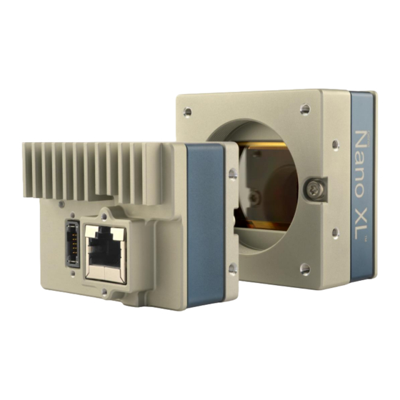
Additional Notes on Genie Nano-5G Identification and Mechanical Identification Label Genie Nano-5G cameras have an identification label applied to the bottom side, with the following information: Model Part Number Serial number MAC ID 2D Barcode CE and FCC logo Additional Mechanical Notes Nano-5G supports a screw lock Ethernet cable as described in Ruggedized RJ45 Ethernet Cables. -
Page 174: Sensor Alignment Specification
Sensor Alignment Specification The following figure specifies sensor alignment for Genie Nano-5G where all specifications define the absolute maximum tolerance allowed for production cameras. Dimensions “x, y, z”, are in microns and referenced to the Genie Nano-5G mechanical body or the optical focal plane (for the z- axis dimension). -
Page 175: Connectors
Connectors • A single RJ45 Ethernet connector for control and video data to the host Gigabit NIC. Additionally for PoE, the Genie Nano-5G requires an appropriate PoE Class 0 or Class 3 (or greater) power source device (such as a powered computer NIC, or a powered Ethernet switch, or an Ethernet power injector). -
Page 176: 10-Pin I/O Connector Pinout Details (Standard Models)
10-pin I/O Connector Pinout Details (Standard Models) Teledyne DALSA makes available optional I/O cables as described in Optional Cable Accessories. Contact Sales for availability and pricing. Pin Number Genie Nano-5G Direction Definition PWR-GND — Camera Power – Ground PWR-VCC —... -
Page 177: I/O Mating Connector Specifications & Sources
I/O Mating Connector Specifications & Sources For users wishing to build their own custom I/O cabling, the following product information is provided to expedite your cable solutions. Samtec web information for the discrete connector and a cable assembly with retention clips follows the table. Part # Description Data Sheet... -
Page 178: Power Over Ethernet (Poe) Support
Samtec connector-cable assembly SFSD-05-28-H-03.00-SR w/retention clips “.050” Tiger Eye™ Double Row Discrete Wire Cable Assembly, Socket” Power over Ethernet (PoE) Support Connect power via the I/O or PoE, not both. Although Nano-5G has protection, differences in ground levels may cause operational issues or electrical faults, resulting in camera faults or failure. -
Page 179: Input Signals Electrical Specifications
Input Signals Electrical Specifications External Inputs Block Diagram External Input Details • Opto-coupled with internal current limit. • Single input trigger threshold level (TTL standard: <0.8V=Logical LOW, >2.4V=Logical HIGH. See lineDetectionLevel feature). • Used as trigger acquisition event, counter or timestamp event, or integration control. •... -
Page 180: External Input Ac Timing Characteristics
External Input AC Timing Characteristics Conditions Description Unit Input Pulse 0V – 3V Input Pulse width High µs Input Pulse width Low 1.22 µs Max Frequency Input Pulse 0V – 5V Input Pulse width High µs Input Pulse width Low 1.28 µs Max Frequency... -
Page 181: External Inputs: Using Common Collector Npn Drivers
External Inputs: Using Common Collector NPN Drivers • External Input maximum current is limited by the Nano-5G circuits to a maximum of 12mA. User IO Power (3V-28V) Camera IO Interface External Signal 2 External Signal 1 Imax = 10mA ( Input 2 ) Imax = 10mA ( Input 1 ) ( Common Ground ) -
Page 182: Output Signals Electrical Specifications
Camera IO Interface RS-422 Compatible Transmitter ( Input 2 ) ( Input 1 ) External Signal ( Common Ground ) Only one Input can be used in this configuration. Output Signals Electrical Specifications External Outputs Block Diagram Current Protection Limiter Current Protection Limiter... -
Page 183: External Output Ac Timing Characteristics
External Output AC Timing Characteristics The graphic below defines the test conditions used to measure the Nano-5G external output AC characteristics, as detailed in the table that follows. Output Common Power Control Signal 100% Camera Output Load rise fall Opto-coupled Output: AC Characteristics Note: All measurements subject to some rounding. - Page 184 General Purpose Output 3 Fast Switching GPO 3 supports a fast switching mode with ground of the user load connected to pin 3 (General Input/Output Common Ground). Note, GPO 1 and GPO 2 do not support fast switching. Test conditions are with front plate temperature ~62 C , FPGA ~85 Output µs)
-
Page 185: External Outputs: Using External Ttl/Lvttl Drivers
External Outputs: Using External TTL/LVTTL Drivers Camera IO User IO Interface Power ( Output 2 ) Signal 2 ( Output 1 ) Signal 1 ( User IO Power ) (Pull-Down) (Pull-Down) LVTTL/TTL Buffer User IO Ground External Outputs: Using External LED Indicators •... - Page 186 • Alternatively one external LED can be connected in the Common Anode configuration. User IO Power Camera IO Interface Set resistor (R) value to not ( Output 2 ) exceed output current of ( Output 1 ) = 30mA. Only one Output (1 or 2) can be used in this configuration.
-
Page 187: Using Nano-5G Outputs To Drive Other Nano-5G Inputs
Using Nano-5G Outputs to drive other Nano-5G Inputs • A synchronization method where one Nano-5G camera signals other Nano-5G cameras. • Note: One Nano-5G output can drive a maximum of three Nano-5G inputs, as illustrated below. Camera IO User IO Interface Power Do not exceed more then three... -
Page 188: Computer Requirements For Nano-5G Cameras
For more information, refer to the Network Hardware Considerations section. • Important: 10/100 Mb Ethernet is not supported by the Genie Nano-5G series of cameras. The Genie Nano-5G Status LED will show that it acquired an IP address (solid Blue) but the Nano- 5G will not respond or function at these slower connections. -
Page 189: Emc Declarations Of Conformity
EMC Declarations of Conformity Models 2050, 2450, 4040, 4060 Nano-5G Series GigE Vision Camera Technical Specifications • 187... -
Page 190: Models 4500, 5420, 8100
Models 4500, 5420, 8100 188 • Technical Specifications Nano-5G Series GigE Vision Camera... - Page 191 Nano-5G Series GigE Vision Camera Technical Specifications • 189...
-
Page 192: Additional Reference Information
Additional Reference Information Choosing a Lens with the Correct Image Circle Each Nano-5G model requires a lens with an image circle specification to fully illuminate the sensor. The following section graphically shows the minimum lens image circle for each Nano-5G model family along with alternative lens types. -
Page 193: Lens Options For Models 4040 & 4060
Lens Options for Models 4040 & 4060 • The following figure shows the lens image circles relative to Genie Nano-5G models using the Sony IMX253 (models 4040) and MX255 (models 4060) sensors. • A typical 1.1” lens will illuminate both sensors models while the 1” lens should only be used with models 4060 to avoid image vignetting. -
Page 194: Lens Options For Models 4500
Lens Options for Models 4500 • The following figure shows the lens image circles relative to Genie Nano-5G models using the On-Semi XGS20000 sensors. • A typical 1.3” lens will illuminate this sensor model 1.3" Lens (~22.5mm) Models Image Circle 4500 (20.4 mm diagonal) 192 •... -
Page 195: Lens Options For Models 5420 & 8100
Lens Options for Models 5420 & 8100 OnSemi XGS30000 sensor models are APS-C format. OnSemi XGS45000 sensor models are Super 35 mm format. • The following figure shows a 43.2mm lens image circle relative to Genie Nano-5G models using the On-Semi XGS30000 (models 5420) and OnSemi XGS45000 (models 8100) sensors. Model 8100 (31.5 mm diagonal) 43.2mm... -
Page 196: Additional Lens Parameters (Application Specific)
Factors include the nature, speed, and spectral characteristics of objects being imaged, exposure times, light source characteristics, environmental and acquisition system specifics, and more. The Teledyne DALSA Web site, http://mv.dalsa.com/, provides an introduction to this potentially complicated issue. Click on Knowledge Center and then select Application Notes and Technology Primers. -
Page 197: Light Sources
Light Sources Keep these guidelines in mind when selecting and setting up light source: • LED light sources are relatively inexpensive, provide a uniform field, and longer life span compared to other light sources. However, they also require a camera with excellent sensitivity. •... -
Page 198: Guidelines For Choosing Ir Cut-Off Filters
Guidelines for Choosing IR Cut-off Filters The following graphic, using a color sensor response spectrum, shows the transmission response of typical filters designed for CMOS sensor cameras. When selecting an IR cut-off filter, choose a near infrared blocking specification of ~650nm. Filters that block at 700nm or longer wavelengths, designed for CCD cameras, are not recommended for Genie Nano-5G color cameras. -
Page 199: Back Focal Variance When Using Any Filter
Back Focal Variance when using any Filter Inserting a filter between a lens and sensor changes the back focal point of the lens used. A variable focus lens simply needs to be adjusted, but in the case of a fixed focus lens, the changed focal point needs correction. -
Page 200: Lens Modeling
Lens Modeling Any lens surrounded by air can be modeled for camera purposes using three primary points: the first and second principal points and the second focal point. The primary points for a lens should be available from the lens data sheet or from the lens manufacturer. Primed quantities denote characteristics of the image side of the lens. -
Page 201: Sensor Handling Instructions
Sensor Handling Instructions This section reviews proper procedures for handling, cleaning, or storing the Genie Nano-5G camera. Specifically the Genie Nano-5G sensor needs to be kept clean and away from static discharge to maintain design performance. Electrostatic Discharge and the Sensor Cameras sensors containing integrated electronics are susceptible to damage from electrostatic discharge (ESD). -
Page 202: Cleaning The Sensor Window
Wipe the window carefully and slowly when using these products. Ruggedized Cable Accessories Teledyne DALSA provides optional I/O cable assemblies for Genie Nano-5G. Users wishing to build their I/O cabling by starting from available cable packages should consider these popular assemblies described below. -
Page 203: Cable Assembly G3-Aioc-Blunt1M
Cable Assembly G3-AIOC-BLUNT1M Nano-5G Series GigE Vision Camera Additional Reference Information • 201... -
Page 204: Cable Assembly G3-Aioc-Blunt2M
Cable Assembly G3-AIOC-BLUNT2M 202 • Additional Reference Information Nano-5G Series GigE Vision Camera... - Page 205 Nano-5G Series GigE Vision Camera Additional Reference Information • 203...
-
Page 206: Cable Assembly G3-Aioc-Brkout2M
Cable Assembly G3-AIOC-BRKOUT2M 204 • Additional Reference Information Nano-5G Series GigE Vision Camera... - Page 207 Nano-5G Series GigE Vision Camera Additional Reference Information • 205...
-
Page 208: Nano-5G Generic Power Supply With No I/O
Nano-5G Generic Power Supply with no I/O 206 • Additional Reference Information Nano-5G Series GigE Vision Camera... -
Page 209: Components Express Right-Angle Cable Assemblies
Components Express Right-Angle Cable Assemblies These cable assemblies can be acquired directly from our partner Components Express. In such cases use the manufacturer’s part number shown on the cable assembly engineering drawing. Cable Assembly: Right-Angle I/O Bunt End Nano-5G Series GigE Vision Camera Additional Reference Information •... -
Page 210: Cable Assembly: Right-Angle I/O To Euro Block
Cable Assembly: Right-Angle I/O to Euro Block 208 • Additional Reference Information Nano-5G Series GigE Vision Camera... -
Page 211: Ruggedized Rj45 Ethernet Cables
Ruggedized RJ45 Ethernet Cables Components Express Inc. has available industrial RJ45 CAT6 cables that on one end have a molded shroud assembly with top/bottom thumbscrews, while the other end is a standard RJ45 (one example shown below). These cables are recommended when Nano-5G is installed in a high vibration environment. -
Page 212: Cable Assembly: Right-Angle Ethernet
Cable Assembly: Right-Angle Ethernet 210 • Additional Reference Information Nano-5G Series GigE Vision Camera... -
Page 213: Right-Angle Cable-Set (Mounted)
Right-Angle Cable-Set (Mounted) Photos show the Components Express Right-Angle combo package (CC C1679-xxM) consisting of a Right-Angle Ethernet cable, Right-Angle I/O to Euro Block, and power supply (not shown). Nano-5G Series GigE Vision Camera Additional Reference Information • 211... -
Page 214: Alysium-Tech "Extreme Rating" Hiflex Ethernet Cable
Alysium-Tech “Extreme Rating” HiFlex Ethernet Cable Alysium-Tech has a cable series for constant movement applications such as cameras mounted on robotic arms or other locations where reliable interconnects are required. Contact Alysium-Tech directly for pricing. 212 • Additional Reference Information Nano-5G Series GigE Vision Camera... -
Page 215: Ip67 Enclosure Products
IP67 Enclosure Products Component Express has designed IP67 enclosures for Nano 5G cameras. Contact them directly for complete information. IP67 Protection Enclosure Designed for Nano 5G Shown below is page one of the Component Express data sheet for this enclosure. Nano-5G Series GigE Vision Camera Additional Reference Information •... -
Page 216: Troubleshooting
Nano-5G is not connected. Important: 10/100 Mb Ethernet is not supported by the Genie Nano-5G series of cameras. The Genie Nano-5G status LED will show that it acquired an IP address (solid Blue) but the Nano-5G will not respond or function at these slower connections. -
Page 217: Problem Type Summary
In multiple NIC systems where the NIC for the Nano-5G is using LLA mode, ensure that no other NIC is in or switches to LLA mode. It is preferable that the Teledyne DALSA DHCP server is enabled on the NIC used with the Nano-5G instead of using LLA mode, which prevents errors associated with multiple NIC ports. -
Page 218: Verifying Network Parameters
Packets by adjusting Power Options. Verifying Network Parameters Teledyne DALSA provides the Network Configuration tool to verify and configure network devices and the Nano-5G network parameters. See section Network Configuration Tool of the Teledyne DALSA Network Imaging manual, if there were any problems with the automatic Nano-5G software installation. -
Page 219: Device Available With Operational Issues
Device Available with Operational Issues This section considers issues with cabling, Ethernet switches, multiple cameras, and camera exposure. All information concerning the Teledyne DALSA Network Configuration Tool and other networking considerations, is available in the Teledyne DALSA Network Imaging manual. -
Page 220: Cabling And Communication Issues
Use the Log Viewer tool (see point below) to check on packet resend conditions. • Run the Sapera Log Viewer: Start•Programs•Teledyne DALSA•Sapera LT•Tools•Log Viewer. Start the Nano-5G acquisition program, such as CamExpert. There should not be any “packet resend” messages, else this indicates a control or video transmission problem due to poor connections or extremely high EMI environments. -
Page 221: Acquisition Error Without Timeout Messages
Streaming video problems range from total loss of image data to occasional loss of random video data packets. The following section describes conditions identified by Teledyne DALSA engineering while working with Nano-5G in various computers and setups. See the Teledyne DALSA Network Imaging manual for information on network optimizations. -
Page 222: No Camera Exposure When Expected
• Verify that network parameters are optimal as described in the Teledyne DALSA Network Imaging Module manual. Ensure the host computer is not executing other network intensive tasks. Try a different Gigabit NIC. -
Page 223: Intel X550 T2 Nic: Low Connection Speed After Camera Reset
Intel X550 T2 NIC: Low Connection Speed After Camera Reset When connected directly to the Intel X550 T2 NIC (not through a switch), following a camera reset and subsequent link speed negotiation, the GigE link speed is set to 1 GigE instead of higher speeds (5 GigE or 2.5 GigE). -
Page 224: Random Invalid Trigger Events
Random Invalid Trigger Events • Do not change the exposure time while grabbing, else an Invalid Trigger Event may be generated. This applies to any exposure mode or trigger source. The Invalid Trigger Event is not catastrophic and only indicates the loss of a video frame. Stopping acquisitions first will avoid this error. -
Page 225: Addenda
This section provides supplemental information about alternative Nano-5G specifications pertaining to various models or legacy firmware revisions. For purchasing information and lead times of optional Nano-5G models that are not part of the typical production cycle, contact Teledyne DALSA Sales. -
Page 226: Using The Special Order Serial Port
The Virtual Serial Port Driver is automatically installed with the Nano-5G Framework. Even if the Nano-5G is used only with third part GigE Vision applications, usage of the serial port requires that the Nano-5G Framework is installed and enabled by using the Teledyne DALSA Network Configuration tool. -
Page 227: Automatic Windows Driver Installation
Automatic Windows Driver Installation The first time the remote serial port control is enabled on a system, an automatic Windows driver update executes as shown in the following screen captures. This update procedure will not repeat on an update of the framework unless the serial port control is first disabled and then follow by an un-install of the Nano-5G driver. -
Page 228: Serial Port Control Category
Serial Port Control Category The Serial Port Control category groups the features related to the optional RS-232 UART serial port. GigE Vision Transport Layer Feature Descriptions Display Name Feature & Values Description Device Version & View 1.00 Serial Port Selector DeviceSerialPortSelector Selects the serial port to control. -
Page 229: Revision History
Revision History Revision Date Major Change Description R:0001 November 22, 2019 Initial release R:0002 December 19, 2019 Added GPO electrical specifications R:0003 April 22, 2020 White Balance cycling and other features R:0004 September 10, 2020 12-bit firmware R:0005 September 29, 2020 Updated timing specifications for 12-bit R:0006 October 13, 2020... -
Page 230: Contact Information
Sales Information Visit our web site: http://www.teledynedalsa.com/en/products/imaging/ Email: mailto:info@teledynedalsa.com Canadian Sales Teledyne DALSA — Head office Teledyne DALSA — Montreal office 605 McMurray Road 880 Rue McCaffrey Waterloo, Ontario, Canada, N2V 2E9 Saint-Laurent, Quebec, Canada, H4T 2C7 Tel: 519 886 6000...