Dyson DC15 Service Manual
Hide thumbs
Also See for DC15:
- User manual (37 pages) ,
- Owner's manual (16 pages) ,
- User manual (11 pages)
Advertisement
Quick Links
Advertisement

Related Manuals for Dyson DC15


Summary of Contents for Dyson DC15
- Page 1 service manual Issued 05/05...
- Page 2 Motorised brushbar Motor location Turn brushabr off at the touch of Patented by Dyson, the motor is suspended a button to protect delicate rugs inside the ball feature, keeping the centre of or hard floors. gravity low and improving manoeuvrability.
-
Page 3: Product Overview
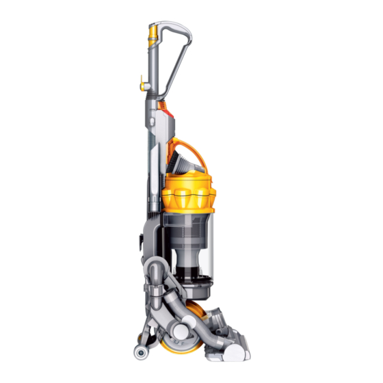
service manual Introduction Product overview Variants Specifications Electrostatic discharge Technical information Electrical testing Electrical circuit & resistance values Electrical fault diagnostic General notes Fitting notes Removing the cleanerhead and yoke assembly Removing and dismantling the yoke assembly Dismantling the cleanerhead Assembling the cleanerhead Assembling and refitting the yoke assembly Refitting the cleanerhead... - Page 4 Low reach floor tool - cleans under low beds and sofas DC15 overview DC15 is the new unique upright from Dyson, with a whole range of features designed to make vacuuming more efficient and less of a chore. The ball is what makes DC15 unique. By replacing conventional wheels with a single ball, it enables the machine to manoeuvre around furniture and obstacles with just a small turn of the wrist.
- Page 5 With the advancement of technology within Dyson products, more sensitive electronic components are being used. Certain variants of Dyson products (i i n n c c l l u u d d i i n n g g D D C C 1 1 5 5 ) contain Printed Circuit Boards (PCBs) which are made from electronic components that are susceptible to damage by electrostatic discharge.
- Page 6 The following insulation tests MUST be carried out prior to and on completion of all services to DC15, and BEFORE any functional checks. You must ensure that a full visual inspection of the product is completed prior to any service activity.
- Page 7 service manual Electrical circuit LIVE NEUTRAL Electrical resistance values Issued 05/05...
- Page 8 2) The vacuum motor of DC15 is fitted with a heat sensitive Thermal Cut-Out (TCO). This will shut the motor down for up to 60 minutes if it reaches a temperature >96 degrees celcius. Excessive temperatures within the motor are usually caused by machine / filter blockages.
- Page 9 Where this symbol is shown ensure ESD protection is used. All screws used in DC15 are Torx T15, unless otherwise stated. Assembly guide The fitting notes contained within this service manual are separated into the following assembly...
- Page 10 service manual Pull the cleanerhead hose off the underside Carefully disconnect the yoke loom from of the valve assembly. the PCB to yoke loom. Turn the product around and undo the Drop the cleanerhead as far forward as screw in the yoke spigot. possible.
- Page 11 service manual Removing and dismantling the yoke assembly Release the yoke loom from the back of the Remove the yoke assembly from the rear yoke assembly. of the cleanerhead top hinge. Prise the large and small gimble clips out of either side of the cleanerhead top hinge using a thin flat bladed screwdriver.
- Page 12 service manual Dismantling the cleanerhead gimble lock arm spring Prise the other end of the gimble lock arm assembly out of the yoke using a thin flat bladed screwdriver, ensuring that you retain the Undo the two fasteners on the rear of the gimble lock arm spring.
- Page 13 service manual Lift out the two brushbar motor top mounts Undo the screw in the underside of the brush from inside the brushbar motor cover assembly. housing. Remove the cleanerhead spring from the Undo the four black screws in the top of the top of the brush housing.
- Page 14 service manual Lift the yoke loom off the top of the brushbar motor. Firmly pull the cleanerhead hose off the rear of the brush housing. Lift the brushbar motor assembly out of the brush housing. Carefully remove the brushbar motor bottom mount from inside the brush housing.
- Page 15 service manual Lift the front edge of the soleplate off the Slide out the brushbar motor front mount brush housing. Then unclip from the rear. from the front of the brush housing. Release both bumper catches from the front of the brush housing using a Torx screwdriver.
- Page 16 service manual Assembling the cleanerhead Lower the bumper rubber into the location slots at the front of the brush housing. Carefully peel the bumper rubber out of the bumper. Align the screw bosses on the bumper with the holes on the brush housing. Firmly press until the catches clip into position.
- Page 17 service manual Lower the glamour cover into the brush housing. Refit the brushbar motor bottom mount into the brush housing. Slide the soleplate wheels onto the axles. Fit both parts into the brush housing. Refit the brushbar motor end mount onto the end of the brushbar motor assembly.
- Page 18 service manual Turn the brush housing over and locate the Push the yoke loom grommet into the locator motor into the brushbar motor front mount. in the brush housing. Locate the grommet onto the brushbar motor assembly. Press the sheaving into the channel on the brush housing.
- Page 19 service manual Align the cleanerhead spring with the cruciform on the base of the brushbar motor Push the endcap assemblies onto the ends cover assembly. of each brushbar and twist into place. Then retighten the endcap fasteners. Lower the brushbar motor cover assembly Refit the cleanerhead hose onto the brush onto the brush housing.
- Page 20 service manual Assembling and refitting the yoke assembly Place the actuator arm spring onto the actuator arm. Using a thin flat bladed screwdriver, position the other end of the spring Carefully press the gimble lock arm spring between the two retainers inside the gimble lock and the actuator arm into the yoke.
- Page 21 service manual Locate the front of the yoke assembly into the rear of the cleanerhead top hinge. Apply a small spot of glue to each of the two ribs highlighted. Refit the gimble clip large and small into either side of the cleanerhead top hinge. Press the yoke loom into the channel on the rear of the yoke.
- Page 22 service manual Refitting the cleanerhead Locate the side of the yoke between the ball Refit the cleanerhead hose onto the underside and valve assembly. Push the cleanerhead into of the valve assembly. position. The cleanerhead is positioned correctly Refit the screw that attaches the top of the when the hole in the side of the yoke assembly yoke to the yoke bracket.
- Page 23 service manual Removing the ball and motor bucket The following parts should be removed, as previously shown, before continuing: cleanerhead and yoke assembly, (pages 6-7) Press the insulation boots into the housing as shown. Neatly tuck the PCB to yoke loom into the side of the yoke leaving enough spare to allow for movement of the cleanerhead.
- Page 24 service manual Undo the three screws in the side of the duct cover noting that the top screw is shorter Undo the two screws in the side of the duct. than the other two. Pull the duct cover and seal off the side of the duct.
- Page 25 service manual Dismantling the motor bucket Lift the small bearing and motor bucket Remove the large bearing from the rear of axle out of the motor bucket base. the motor bucket seal/loom assembly. Slide the small bearing off the motor bucket axle.
- Page 26 service manual Peel the fancase seal off the base of the Unclip the motor bucket seal/loom motor. assembly from either side of the motor. Stretch the motor bucket seal/loom assembly over the fancase seal and remove from the motor. Pull the motor mount off the top of the motor.
- Page 27 service manual Assembling the motor bucket Position the top of the motor bucket seal/loom assembly into the channel on the Align the pip on the base of the motor motor mount. mount with the hole in the top of the motor and push the motor mount onto the motor.
- Page 28 service manual Slide the small bearing onto the motor bucket axle. Lower both parts into the front of the motor bucket base. Lower the channel on the motor mount onto the detail inside the front of the motor bucket base. Lower the rear of the motor bucket seal into the channel in the rear of the motor bucket base.
- Page 29 service manual Refitting the motor bucket and ball Push the rear of the motor bucket into the side of the duct. Refit the two screws. Align the screw bosses on the rear of the motor bucket seal/loom assembly with the Lower one half of the ball assembly onto locators in the base of the duct.
- Page 30 service manual Removing and dismantling the axlestand Firmly push the top of the axlestand out of the channel in the rear of the duct. Fit the duct cover seal to the duct. Dress the looms into the duct channel under the seal. Carefully remove the circlip from the end of the stabiliser axle using a pair of circlip pliers.
- Page 31 service manual Removing the stabiliser Carefully release both legs of the axlestand spring from the stabiliser using a pair of long nosed pliers. Prise the stabiliser circlip off the end of the stabiliser using a large flat bladed screwdriver. Release the axle stand spring from the rear Remove the screw in the static cover.
- Page 32 service manual Refitting the stabiliser Locate the end of the stabiliser into the base of the duct. Push the side of the stabiliser out the rear of the valve assembly. Align the detail on the other end of the stabiliser with the rear of the spring mount assembly.
- Page 33 service manual Assembling and refitting the axlestand Fit the pedal spring onto the cruciform on the axlestand. Lower the pedal onto the axle stand ensuring the cruciform on the base of it aligns with the spring. Locate the end of the stabiliser circlip into the channel on the end of the stabiliser.
- Page 34 service manual Removing and dismantling the valve cuff and valve seal Slide another washer, the second stabiliser wheel and then the last washer onto the end of the stabiliser axle. Carefully refit the circlip. Press the cyclone release catch to remove the cyclone and bin assembly from the product.
- Page 35 service manual Assembling and refitting the valve cuff and valve seal Locate the tab on the valve seal into the retainer on the valve cuff. Lower the remainder Locate the end of the screwdriver under the of the valve seal into the valve cuff. When retaining clip.
- Page 36 service manual Removing and dismantling the valve assembly Before continuing, the following parts need to be removed as previously shown: cleanerhead and yoke, (pages 6-7) ball and motor bucket, (pages 20-21) Pull the front face of the moving cover off the retaining peg on the rear of the valve assembly.
- Page 37 service manual Assembling and refitting the valve assembly Remove the wand from the hose/u-bend assembly. Lower the hose/u-bend assembly. Push the stabiliser to one side. Slide the Then pivot it out of the retaining clip. valve assembly into the base of the duct below the duct valve seal.
- Page 38 service manual Removing the powercord assembly and switches Switch cover release catch Remove the wand handle from the top of Refit the moving cover onto the rear the duct. Undo the three screws in the rear of spring. Refit the rear spring onto the retaining the duct.
- Page 39 service manual Refitting the powercord assembly and switches Fit the powercord assembly into the duct ensuring that the end of the outer insulation extends past the screw boss. Slide the Disconnect the neutral wire from the internal protector into the side of the duct. cable.
- Page 40 service manual Removing and refitting the internal cable Remove the duct cover and duct seal from Attach the red wire to the remaining the side of the duct. Carefully slide the PCB out terminal on the brushbar switch. Dress all of the duct.
- Page 41 service manual Removing and refitting the PCB to yoke loom Locate the end of the internal cable into the side of the duct. Push the grommet into the Remove the duct cover and duct seal. duct. Important: ensure that the grommet is Carefully snip the 3 cable ties that hold the adequately sealed within the duct as this is an looms together.
- Page 42 service manual Dismantling the duct assembly Remove the wand handle assembly and Twist the yoke bracket within the channel hose/u-bend assembly from the rear of the duct. until the grommet is exposed. Remove the cyclone and bin assembly from the Release the grommet from the duct.
- Page 43 service manual Undo the long screw on the inside of the duct. Remove the upright switch cover and Peel the inlet seal off the side of the duct. upright switch actuator. Carefully pull the exhaust seal and filter duct assembly off the side of the duct. Peel the Carefully detach the upright switch from the seal of the duct filter.
- Page 44 service manual Hose/u-bend and wand assemblies Peel the duct valve seal off the side of the Press both hose release catches and slide duct. the wand handle assembly out of the hose/u- bend assembly. Push the wand catch backwards until it releases from the wand handle assembly.
- Page 45 service manual Cyclone and bin assemblies Assembling the duct assembly Firmly pull the FDC seal off the base of the Fit the spring onto the cruciform on the cyclone assembly. cyclone release catch. Clip one leg of the When refitting the FDC seal ensure the top of catch into the retainer on the duct.
- Page 46 service manual Push the tool clip into the side of the duct. Refit the inlet seal onto the side of the duct. Locate the ends of the upright switch loom into the hole on the inside of the duct. Connect the upright switch loom to the two outer Locate the thick part of the wall on the filter duct into the wide channel inside the...
- Page 47 service manual Once you have fitted all the previous parts to the duct, you should continue to fit the following main assemblies in order as previously shown: valve assembly, (pages 34-35) stabiliser and axlestand, (pages 29-31) motor bucket and ball, (pages. 26-27) Once the previous main assemblies are fitted, you should continue to fit the following parts: internal cable and PCB assembly, (page 38)
- Page 48 service manual Cleanerhead and yoke assembly Gimble lock Yoke spigot arm assy Yoke assy Screw Screw Yoke bracket Cleanerhead hose assy Actuator arm spring Gimble lock arm spring Hose guard Yoke cover Gimble clip small Cleanerhead spring Brushbar motor cover assy Gimble clip large Screw Yoke loom assy...
- Page 49 service manual Duct, valve and stabiliser On/off switch On/off switch Cable clip button Spade connector boot Brushbar switch button Powercord assy Brushbar switch Duct assy Cyclone release catch Cyclone release catch spring Switch cover Screw Filter duct Internal cable Lower cable winder PCB assy Exhaust seal...
- Page 50 service manual Motor bucket and ball Screw Ball assy Motor bucket assy Motor bucket seal/loom assy Small bearing Motor bucket axle Motor mount Large bearing Motor Fancase seal Screw Issued 05/05...
- Page 51 service manual Cyclone, bin, wand and hose/u-bend assemblies Wand cap Cyclone assy Wand handle Washable filter assy assy Hose/U-bend assy FDC seal Bin assy Bin base assy U-bend seal Post filter cover HEPA post filter assy STD post filter Mini turbine head assy Mini turbine head adaptor...