Table of Contents
Advertisement
Available languages
Available languages
Utilitech & UT Design
is a registered
®
trademark of LF, LLC. All rights reserved.
ATTAcH YOur receiPT Here
Date Code
Questions, problems, missing parts? Before returning to your retailer, call our customer
service department at 1-866-994-4148, 8 a.m. - 8 p.m., EST, Monday - Friday.
UT822
AB12308
®
Purchase Date
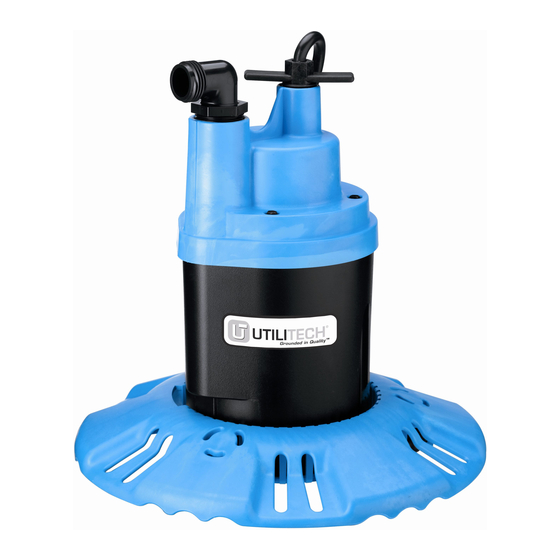
submersibLe PumP
6678 0912
1
ITEM #0240062
POOL cOver
MODEL #UT25PCP
Español p. 13
Lowes.com
®
Advertisement
Chapters
Table of Contents

Related Manuals for Utilitech UT25PCP


Summary of Contents for Utilitech UT25PCP
- Page 1 ITEM #0240062 POOL cOver ® submersibLe PumP Utilitech & UT Design is a registered MODEL #UT25PCP ® trademark of LF, LLC. All rights reserved. Español p. 13 6678 0912 ATTAcH YOur receiPT Here Purchase Date Date Code Questions, problems, missing parts? Before returning to your retailer, call our customer service department at 1-866-994-4148, 8 a.m.
-
Page 2: Table Of Contents
TABLE OF CONTENTS Package Contents ....................... 3 Hardware Contents....................... 4 Safety Information ....................... 4 Assembly Instructions......................5 Installation Instructions ......................6 Operating Instructions ......................7 Troubleshooting ......................... 10 Warranty ..........................11 Replacement Parts List ..................... 12 PrODucT sPeciFicATiONs sPeciFicATiONs PerFOrmANce Power supply required: 115 V, 60 Hz Discharge 20 ft... -
Page 3: Package Contents
PAcKAGe cONTeNTs Handle PArT DescriPTiON QuANTiTY Pre-assembled GFCI-protected plug Motor Impeller 6708 1012 Assembly required Garden hose adapter Shield Screen Base ® Lowes.com... -
Page 4: Hardware Contents
HArDWAre cONTeNTs (shown actual size) Base Screw (#8 x .930 Lg. Pan HD) Qty. 3 sAFeTY iNFOrmATiON Please read and understand this entire manual before attempting to assemble, operate or install the product. SAVE THESE INSTRUCTIONS - This manual contains important instructions that should be followed during installation, operation, and maintenance of the product. -
Page 5: Assembly Instructions
AssembLY iNsTrucTiONs risk of electric shock. Do not plug in pump until assembly is complete. 1. Turn pump body upside down and install the shield (E) as shown. Align part number with anti- airlock hole 5841 0408 2. Install the screen (F) as shown. Do not insert screws yet. -
Page 6: Installation Instructions
INSTALLATION INSTRUCTIONS risk of electric shock. Can shock, burn or kill. Do not use power cord to lift motor. Always use handle. 1. Pump should always stand upright on base when operating. Do not suspend pump by means of discharge hose or power cord. Keep pump screen clear. -
Page 7: Operating Instructions
OPerATiNG iNsTrucTiONs risk of electric shock. Can shock, burn GFCI-protected outlet or kill. Do not handle pump or pump motor with wet hands or when standing on wet or damp surface, Reset GFCI-protected plug button or in water. Disconnect power from pump before Garden hose handling, servicing, or attempting to repair pump. - Page 8 OPerATiNG iNsTrucTiONs NOTE: If the overload protector stops the pump repeatedly, disconnect the power from the pump and check it to find the problem. Low voltage, a clogged impeller, too much back pressure in the discharge hose (as when pumping through 50 ft. of coiled hose), or extended running of pump with no load can all cause overheating.
- Page 9 OPerATiNG iNsTrucTiONs Airlocks An airlock is an internal air bubble which prevents normal flow of water and can cause the pump to overheat and fail. This pump has an anti-airlock hole in the pump body (Figure 7). If you suspect an airlock, unplug the pump, clean out the anti-airlock hole with a piece of wire and restart the pump.
-
Page 10: Troubleshooting
TrOubLesHOOTiNG risk of electrical shock and sudden starts. Can shock, burn or kill. Can cause electrical shock and personal injury. Disconnect electrical power to pump before attempting to troubleshoot or work on it. PrObLem POssibLe cAuse cOrrecTive AcTiON Pump won’t start 1. -
Page 11: Warranty
Twelve (12) month Limited Warranty Warranty Product Period UT25PCP 2 Years General Terms and conditions; Limitation of remedies You must pay all labor and shipping charges necessary to replace product covered by this warranty. This warranty does not apply to the following: (1) acts of God;... -
Page 12: Replacement Parts List
Base PS70-81 NOTICE: To purchase a check valve, call Customer Service at 866-994-4148 and order part number PW73-63. Printed in USA and China Utilitech & UT Design is a ® registered trademark of LF, LLC. All rights reserved. ® Lowes.com... - Page 13 ARTÍCULO #0240062 bOmbA PArA ® cubierTA De PisciNA / sumerGibLe Utilitech & UT Design® es una marca registrada de LF, LLC. Todos los derechos reservados. MODELO #UT25PCP 6678 0912 ADJuNTe su recibO AQuÍ Fecha de compra Código de fecha ¿Preguntas, problemas, piezas faltantes? Antes de volver a la tienda, llame a nuestro Departamento de Servicio al Cliente al 1-866-994-4148, de lunes a viernes de 8 a.m.
- Page 14 ÍNDice Contenido del paquete ...................... 15 Accesorios de ferretería ..................... 16 Información de seguridad ....................16 Instrucciones de ensamblaje ....................17 Instrucciones de instalación ....................18 Instrucciones de funcionamiento ..................19 Solución de problemas ...................... 22 Garantía..........................23 Lista de piezas de repuesto ....................24 esPeciFicAciONes DeL PrODucTO esPeciFicAciONes Suministro de electricidad necesario:...
-
Page 15: Contenido Del Paquete
cONTeNiDO DeL PAQueTe Manija PieZA DescriPciÓN cANTiDAD Preensamblado Enchufe protegido por un interrup- tor de circuito con descarga a tierra (GFCI, por sus siglas en inglés) Motor 6708 1012 Impulsor Requiere ensamblaje Adaptador de manguera para jardín Protector Malla Base ®... -
Page 16: Accesorios De Ferretería
AccesOriOs De FerreTerÍA (se muestran en tamaño real) Tornillo de la base (#8 x .930 Lg. de cabeza plana) Cant. 3 iNFOrmAciÓN De seGuriDAD Lea y comprenda completamente este manual antes de intentar ensamblar, usar o instalar el producto. GUARDE ESTAS INSTRUCCIONES: este manual contiene información importante que debe seguirse durante la instalación, el funcionamiento y el mantenimiento del producto. -
Page 17: Instrucciones De Ensamblaje
iNsTrucciONes De eNsAmbLAJe riesgo de descarga eléctrica. No enchufe la bomba hasta haber completado el ensamblaje. 1. Coloque el cuerpo de la bomba de manera invertida e instale el protector (E) como se muestra. Alinee el número de pieza con el orificio ... -
Page 18: Instrucciones De Instalación
iNsTrucciONes De iNsTALAciÓN riesgo de descarga eléctrica. Puede producir una descarga eléctrica, quemaduras o causar la muerte. No use el cable de alimentación para levantar el motor. Siempre use la manija. 1. La bomba siempre debe quedar en posición vertical sobre la base cuando está en funcionamiento. -
Page 19: Instrucciones De Funcionamiento
iNsTrucciONes De FuNciONAmieNTO riesgo de descarga eléctrica. Puede Tomacorriente protegido por un interruptor de circuito con producir una descarga eléctrica, quemaduras Botón de descarga a tierra (GFCI) o causar la muerte. No manipule la bomba o el restableci- Enchufe protegido por un miento motor con las manos húmedas ni cuando esté... - Page 20 iNsTrucciONes De FuNciONAmieNTO 1. El motor está equipado con un protector de sobrecarga térmico con restablecimiento automático. Si el motor se calienta demasiado, el protector de sobrecarga detendrá el motor antes de que resulte dañado. Cuando el motor se haya enfriado lo suficiente, el protector de sobrecarga se restablecerá y el motor se iniciará...
- Page 21 iNsTrucciONes De FuNciONAmieNTO riesgo de descarga eléctrica. Puede producir una descarga eléctrica, quemaduras o causar la muerte. Desconecte la bomba de la fuente de alimentación antes de desensamblarla o de limpiar el impulsor. 5. Si el rotor aún está bloqueado, desenchufe la bomba, quite la base (G), el protector (E) y la malla (F) y limpie el impulsor (C).
-
Page 22: Solución De Problemas
sOLuciÓN De PrObLemAs riesgo de descarga eléctrica y arranques bruscos. Puede producir una descarga eléctrica, quemaduras o causar la muerte. Puede causar descargas eléctricas y lesiones personales. Desconecte la alimentación eléctrica de la bomba antes de intentar solucionar problemas o trabajar en ella. -
Page 23: Garantía
(12) meses Período de cobertura de Producto la garantía UT25PCP 2 años Términos y condiciones generales; Límite de soluciones Usted debe pagar toda mano de obra y costos de envío necesarios para remplazar el producto que cubre esta garantía. Esta garantía no cubre lo siguiente: (1) desastres naturales;... -
Page 24: Lista De Piezas De Repuesto
Base PS70-81 UU. y China AVISO: Para comprar una válvula de control, llame a Servicio al cliente al 866- Utilitech & UT Design® es una marca registrada de LF, 994-4148 y solicite la pieza número PW73-63. LLC. Todos los derechos reservados.