
Related Manuals for Riello RTS 2S Seies


Summary of Contents for Riello RTS 2S Seies
- Page 1 S T E E L B O I L E R S RTS 2S INSTALLATION, OPERATION, MAINTENANCE AND SYSTEM MANAGEMENT MANUAL...
- Page 2 CONFORMITY The r RTS 2S boilers conform to the Efficiency Directive 92/42/CEE. When used in conjunction with a CE marked jet burner, they also satisfy the requirements of the Gas Appliances Directive 2009/142/EC (until 20 April 2018) and Regulation (EU) 2016/426 (from 21 April 2018) and applicable sections of the Electromagnetic Compatibility Directive 2014/30/UE and Low Voltage Directive 2014/35/UE.
- Page 3 Technical Assistance Centres also stock any original spare parts that might be required. This instruction manual contains important instructions and precautions that must be observed to ensure the trouble-free installation and efficient functioning of your r RTS 2S boiler. Please accept our renewed thanks for your purchase. Riello S.p.A.
-
Page 4: Table Of Contents
CONTENTS GENERAL General safety information page 5 Precautions “ Product description “ Control panels “ Recommended burners “ Product identification “ Technical specifications “ SYSTEM MANAGER Start up page 11 Temporary shutdown “ Preparing for extended periods of disuse “ Cleaning “... -
Page 5: General
GENERAL SAFETY INFORMATION The boiler is delivered in separate crates. Check Periodically check that operating pressure in the water circuit is over 1 bar but below the maximum that it is complete, undamaged and as ordered as soon as you receive it. Report any discrepancies or limit specified for the boiler. -
Page 6: Product Description
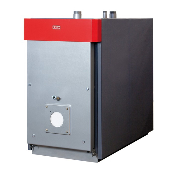
PRODUCT DESCRIPTION r RTS 2S steel boilers are high efficiency triple flue Once out of the tube bundle, the flue gases pas through a chamber at the rear of the boiler, and into the vent flue. pass boilers for central heating systems. When com- Their special design (with tube bundle over the combus- bined with a storage cylinder, they can also be used to tion chamber) makes these boilers far narrower than... -
Page 7: Control Panels
CONTROL PANELS The r control panels that can be used with r RTS 2S steel boilers are listed below. These control panels cater for all the needs of the heating system and of all the devices installed in it. 5000 TMR 2 for central heating 5000 CL/M for central heating with a single stage, two stage, only with single/two stage ther-... -
Page 8: Recommended Burners
RECOMMENDED BURNERS The burners recommended to obtain the best possible performance from r RTS 2S boilers are: BURNER RTS 2S Burner plate Model Code Type 1012 1200 1355 1500 1850 Code RS 44/1 MZ t.c. 3788600 Single stage • 4031395 RS 44 MZ t.c. - Page 9 IMPORTANT NOTES FOR BURNER INSTALLATION L < S Before fixing the burner to the boiler, make sure that: - The door opens the right way (see the relevant sections for details on how to reverse the door). - The length (L) of the burner fixing bolts is less than (S), i.e.
-
Page 10: Product Identification
PRODUCT IDENTIFICATION The boilers are identified by two plates: - Serial number plate This is located on the boiler body and speci- fies the serial number, model, furnace power and maximum operating pressure. - Data plate 2 3 2 7 0 0 0 0 5 8 1 This lists the technical specifications and per- formance of the product. -
Page 11: System Manager
START UP Have r’s Technical Assistance Service start up your r RTS 2S boiler for the first time. Once this has been done, the boiler can be left to function automatically. Under certain circumstances, such as after long periods of disuse, the service engineer responsible for the boiler may need to re-start it without involving the Technical Assistance Service. -
Page 12: Temporary Shutdown
If a “LOCKOUT SHUTDOWN” occurs, wait about The burner should now ignite and remain in operation 30 seconds before resetting the burner. until the set temperature is reached. To reset the burner, press the red button light on the If any ignition faults or malfunctions occur, the burner burner and wait until the flame ignites. -
Page 13: Preparing For Extended Periods Of Disuse
PREPARING FOR EXTENDED PERIODS OF DISUSE If the boiler is not going to be used for an extended period of time, perform the following operations: - Turn the control panel power switch OFF and make sure that the green power indicator goes out. - Turn the mains power switch OFF. -
Page 14: Maintenance
MAINTENANCE The Law requires that THE PERSON RESPONSIBLE r’s Technical Assistance Service is qualified to satisfy FOR SYSTEM MANAGEMENT MUST ENSURE THAT these legal requirements and can also provide useful PROFESSIONALLY QUALIFIED HEATING ENGINEERS information on MAINTENANCE PROGRAMMES designed UNDERTAKE PERIODIC MAINTENANCE to guarantee:... -
Page 15: Unpacking The Product
UNPACKING THE PRODUCT r RTS 2S steel boilers come in: RTS 115÷526 2S RTS 1355÷1850 2S 1) BOILER BODY CRATE to which is attached the documentation envelope (A) containing: - Instruction manual - Data label (to be applied to the casing on comple- tion of the installation) - Certificate of Warranty and water test certificate - Bar code labels... -
Page 16: Overall Dimensions And Weights
OVERALL DIMENSIONS AND WEIGHTS RTS 2S 850 1012 1200 1355 1500 1850 A - Width 890 1000 1000 1047 1047 1147 1147 1237 mm A1 - Base width 980 1070 1070 1160 mm B - Depth 1155 1330 1500 1500 1660 1960 2085 2375 2375 2657 2657 2954 2954 3173 mm B1 - Base depth 860 1010 1180 1180 1296 1596 1692 1965 1965 2236 2236 2533 2533 2754 mm C - Height... -
Page 17: Place Of Installation
PLACE OF INSTALLATION RTS 2S When installing the boiler, allow sufficient space steel boilers must be installed in a dedi- around it to access all safety and control devices cated boiler room, with adequately sized vents, in com- and to permit easy maintenance. pliance with applicable laws and standards. -
Page 18: Installation In Older Systems And Systems Requiring Modernisation
INSTALLATION IN OLDER SYSTEMS AND SYSTEMS REQUIRING MODERNISATION When installing these boilers in old systems or systems requiring modernisation, always perform the following checks: - Make sure that the stack is able to withstand the temperature - Make sure that a suitable water treatment system is of the combustion gases and that it has been designed and installed if the quality of the supply/recirculation water made in compliance with applicable standards. - Page 19 The choice of system components and the method of their installation are left up to the heating engineer installing the system. Installers must use their expertise to ensure proper installation and functioning in compliance with all applicable legislation. Circuits filled with anti-freeze must be fitted with water disconnectors. INSTALLER...
-
Page 20: Anti-Condensate Pump
ANTI-CONDENSATE PUMP An anti-condensate pump operates during periods of no heat request to avoid damage until the boiler returns to a stable operating temperature. While the system is operating, this pump must guarantee a flow rate between 20 and 30% maximum flow to ensure a water return temperature no lower than 55 °C. -
Page 21: Boiler Door Hinges
The stack must guarantee the minimum draught Joints must be sealed using appropriate materials specified by applicable technical standards, (e.g. filler, mastic or silicone based sealant). assuming zero pressure at the connection to the flue gas exhaust. Uninsulated flues are potentially dangerous and Inadequate or badly dimensioned stacks and exhausts can cause burns. - Page 22 System A - RTS 115÷410 2S - Make sure that the main door fixing bolts (1) are securely tightened. - Remove the top safety bolts (2) and the door stop - Insert a spanner through the slot in the side of the bracket (3).
- Page 23 - Fit the top door stop bracket (3) to the opposite side - Completely unscrew the main fixing bolts (1) and of the door and fix it in place with the safety bolts (2). open the door. (These bolts are captive in the door - Fit the bottom door stop bracket (5) to the opposite and cannot be removed.) side of the door and fix it in place with the safety...
- Page 24 System B - RTS 526÷1012 2S Open the door and use a hacksaw or file to remove the cutout from the front head on the opposite side to the door hinges. Reclose the door and secure it with the bolts (2). Remove the plug (1), taking care not to lose the spring from inside the threaded tube.
-
Page 25: Earth Connection
EARTH CONNECTION - Fit the nut and washer (1) to the earth terminal and A terminal is provided on the front boiler head to connect tighten the nut. the boiler body to an efficient earth system. - Connect the other end of the cable to the system’s earth bar. -
Page 26: Fitting The Casing Panels
FITTING THE CASING PANELS Models RTS 115÷850 2S - Push out the pre-formed cutouts in the boiler’s side TECH) on the left panel (4) or right panel (5) as panel ((4) or (5) depending on what side you want instructed in the control panel’s own instruction man- to install the control panel) corresponding to the oval ual. - Page 27 Models RTS 1012÷1850 2S - Push out the pre-formed cutouts in the boiler’s side - Fit your chosen control panel (r 5000 or r panel ((4) or (5) depending on what side you want TECH) on the left panel (4) or right panel (5) as to install the control panel) corresponding to the oval instructed in the control panel’s own instruction manual.
-
Page 28: Location Of Sensors
LOCATION OF SENSORS Insert the sensors belonging to the safety devices into the copper socket (P). BOILER SAFETY DEVICE sensor Clip Guide Sensor Sensor Sensor INSTALLER... -
Page 29: Preparing For Initial Start-Up
PREPARING FOR INITIAL START-UP It is essential to perform the following checks before starting up or testing the functioning of your r RTS 2S boiler. In particular, check that: - The water and gas cocks are open. - There is an adequate fuel supply. - The expansion vessel is properly charged. -
Page 30: Initial Start-Up
INITIAL START-UP Once you have completed all the preparatory steps, proceed as follows to start up the boiler for the first time: - If the system is equipped with a temperature controller or timer thermostat, make sure that it is switched on. - Adjust the timer thermostat/s or temperature controller to the desired temperature (~20°... -
Page 31: Checks During And After Initial Start-Up
CHECKS DURING AND AFTER INITIAL START-UP Once the boiler has started up, make sure that it shuts down and re-starts properly when the following actions are taken: - The boiler thermostat setting is changed - Power to the control panel is switched off and on again - The room thermostat or timer thermostat is adjusted. -
Page 32: Maintenance
MAINTENANCE Regular maintenance is a legal requirement. It is also Have your boiler serviced either by r’s Technical essential for the safety, efficiency and durability of the Assistance Service or by a qualified heating engineer. boiler. Proper maintenance keeps consumption and emissions down, and ensures that the boiler continues to Analyse the combustion fumes before commencing any operate reliably over time. -
Page 33: Cleaning The Boiler
CLEANING THE BOILER Clean the boiler and remove any carbon deposits from the surfaces of the heat exchanger at least once a year. This not only extends the boiler’s working life, but also keeps it efficient in terms of heat output and consumption. Proceed as follows to clean the boiler. -
Page 34: Troubleshooting
TROUBLESHOOTING FAULT CAUSE CORRECTIVE ACTION The boiler becomes dirty very Check the adjustment of the Burner badly adjusted quickly burner (perform flue gas analysis) Clean the flue gas pipes Blockage in stack and stack Burner air intake dirty Clean the burner air intake The boiler does not reach Boiler dirty Clean the flue gas pipes... - Page 35 FAULT CAUSE CORRECTIVE ACTION The boiler does not start up, Make sure that the multi-compart- Transfer pump auxiliary control but there is no error signal. ment zone water circuit has been safety thermostat has tripped correctly bled. Check that the transfer pumps are functioning correctly.
- Page 36 RIELLO S.p.A. 37045 Legnago (VR) Tel. 0442630111 - Fax 0442630371 - www.riello.it As part of the company’s ongoing commitment to perfecting its range of products, the appearance, dimensions, technical data, equipment and accessories may be subject to variation.