Advertisement
Quick Links
Download this manual
See also:
Owner's Manual
Advertisement

Related Manuals for Fostex VM88


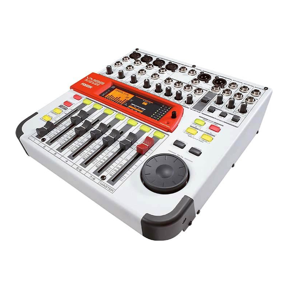
Summary of Contents for Fostex VM88
- Page 1 Service Manual Model 8CH Digital Mixer with DSP Effects FOSTEX CORPORATION 3-2-35 Musashino, Akishima, Tokyo, Japan 196-0021 FOSTEX CORPORATION OF AMERICA 15431 Blackburn Ave., Norwalk, CA 90650, U.S.A. © PRINTED IN JAPAN MAR. 2000 8288789000...
- Page 2 SPONDANTE DE LA PRISE ET POUSSER JUSQU' AU FOND. The exclamation point within an equilateral triangle is intended to alert the user to the presence of important operating and mainte- nance (servicing) instructions in the literature accompanying the appliance. VM88...
-
Page 3: Table Of Contents
Service mode, exploded view, PCB assembly, parts list and circuit diagrams are given in this manual to assist the service technician in maintaining the Model VM88. The following accessories are supplied with VM88 as the standard accessories. Owner's manual : 8288458000 (for export & domestic model) Following is the packing material for the Model VM88. -
Page 4: Specifications
VM88 1. SPECIFICATIONS Specification Unit 0 dBV = 1 Vr.m.s., 0 dBu = 0.775 Vr.m.s. Standard Input INPUT 1 ~ 4 Connector XLR Cannon (MIC) Ø 6 mm TRS phone jack (LINE) Input level -50 dBu ~ -10 dBu (MIC) - Page 5 VM88 /RST_DSP[1...3] /WRQ_DSP[1...3] SEL3 SEL2 SEL1 SEL3 SEL2 SEL1 SEL1 SEL2 SEL3 Fader (VR) Position at Standard Input / Output (continued) INPUT 5 ~ 8 (TRS) +4 dBu, 1 kHz L (R) Master Fader Adjust so that ST OUT level is at -10 dBV. ( ST OUT SW: ON)
-
Page 6: Controls, Indicators And Connectors
VM88 2. CONTROLS, INDICATORS AND CONNECTORS < Top Panel Section > 1. Input connector [ MIC (2: HOT) / LINE ] 17. Enter key [ ENTER ] 2. AUX send jack [ AUX SEND 1, 2 ] 18. Exit key [ EXIT ] 3. -
Page 7: Service Mode
VM88 AOUTR2- AUXSEND_AR- AOUTR2+ AUXSEND_AR+ AOUTL2- AOUTL2+ AOUTR1- AOUTR1+ AOUTL1- AOUTL1+ VRDAL AVSS AVDD ARDAH VCOM VRADL AVSS AVDD VRADH AINR- AINR+ AINL- AINL+ R952 C974 C973 C972 AOUTR2- AOUTR2+ AOUTL2- AOUTL2+ AOUTR1- AOUTR1+ AOUTL1- AOUTL1+ VRDAL AVSS AVDD ARDAH... - Page 8 While holding down both the PAN/EQ and EFF/AUX keys, press the EFF 2 key. The LCD display will show the voltage of the memory backup battery inside the VM88 for about a second, and then return to the normal display mode.
- Page 9 VM88 E-LCD /+48 (CPURX) RS-LCD (CPUTX) /DIG00 DIG0 /DIG01 DIG1 /DIG02 DIG2 /DIG03 DIG3 R916 CLK-DSP SO-DSP SI-DSP MMOD OSC1 OSC2 VREF+ VREF- 0.01 C915 0.01 C914 0.01 C913 0.01 C912 0.01 C911 0.01 C910 0.01 C909 3-5. Key Check While holding down both the PAN/EQ and EFF/AUX keys, press the LEVEL ADJUST key.
-
Page 10: Exploded View, Pcb Assembly And Parts List
ON. In that case, the battery has to be replaced. Please understand that replacing the battery will initialize the backup data. If you would like to retain the backup data, replace the battery while the power is ON. 4. EXPLODED VIEW, PCB ASSEMBLY AND PARTS LIST VM88 OVERALL EXPLODED VIEW & PARTS LIST Ref. No. Part No. - Page 11 VM88 BBT3 x 8BZn BBT3 x 8BZn *: Attached to the connector BBT3 x 6BZn BBT3 x 8BZn BBT3 x 6BZn BBT3 x 6 BBT3 x 8BZn B3 x 6BZn BBT3 x 6BZn B3 x 6BZn BTT4 x 8BZn VM88...
- Page 12 VM88 VM88 PCB ASSEMBLIES C773 R712 C763 C740 U702 C752 C753 C710 C799 C701 C731 C811 R893 R892 U802 C837 U799 R827 U811 C884 C885 U604 C601 U602 C663 U810 C642 C643 U601 C647 U504 U800 R563 C501 U502 C542...
- Page 13 VM88 C104 C146 R127 C114 R141 L106 R131 R111 C971 C126 L101 C970 R117 R938 L121 J131 C117 R126 R111 R123 C969 R107 L105 R101 R191 R181 R108 C931 R101 R171 C107 C948 R936 R935 R112 R102 L111 R122 R124...
- Page 14 VM88 J104 D203 D205 R109 D204 D206 R107 D107 D106 D105 D104 D103 D102 D101 J106 R209 R206 R208 R207 R205 R700 R600 R500 R400 R300 R200 R100 D201 VM88...
- Page 15 VM88 D201 D101 R308 R307 D102 D103 D104 D105 D106 D107 R107 D206 D204 R109 D205 D203 J100 VM88 R100 R200 R300 R400 R500 R600 R700 J101...
- Page 16 • Main PCB assy Ref. No. Part No. Description 8274 2760 00 PCB Assy, Main, VM88 Ref. No. 8251 9941 01 Plain PCB, Main, VM88 U101~401 8236 5405 00 ST, AN, NJM2068MD (TEI) U102~402 8236 5412 00 ST, AN, op amp, NJM4565M U103~403 8236 5050 11 ST, AN, op amp, NJM2115M (TEI) : FOR CONTINUED PROTECTION RISK OF FIRE.
- Page 17 VM88 Ref. No. Part No. Description U501, 601 8236 5405 00 ST, AN, NJM2068MD (TEI) Ref. No. Part No. U502, 602 8236 5412 00 ST, AN, op amp, NJM4565M R001 8230 1111 01 H, metal, 1W, 100 , 5%, F15...
- Page 18 VM88 Ref. No. Part No. Description Ref. No. R521, 621 8230 5101 03 ST, carbon, 1/15W, 10k , 5% R781~784 8230 5101 03 ST, carbon, 1/15W, 10k , 5% R522, 622 8230 5100 00 ST, carbon, 1/15W, 0 , 5%...
- Page 19 VM88 JOG1 JOG0 VR[0..6] DIG1 DIG0 DIG3 DIG2 DIG[0...3] LEDK[0...7] LCD_RS LCD_E Ref. No. R974 R975 R976 R978~980 8230 5101 01 ST, carbon, 1/15W, 100 , 5% R981 R982 R983~985 8230 5101 03 ST, carbon, 1/15W, 10k , 5% R986...
- Page 20 VM88 Ref. No. Part No. Description Ref. No. C733 8233 0491 06 ST, ALU, 16V, 10 F, 20%, MV C927 C734 8233 5122 20 ST, CER, 50V, 22pF, 5%, CC11SL C928, 929 8233 5151 04 ST, CER, 25V, 0.1 F, +80, CC11F...
- Page 21 X902 8256 1700 01 Resonator, ST, XTL, 22.579MHz, • Display PCB assy Ref. No. Part No. 8274 2730 00 PCB Assy, Display, VM88 8251 9941 02 Plain PCB, Display, VM88 Ref. No. Part No. U301 8236 0836 00 IC, QFP, DG, LCD driver, HD44780U...
-
Page 22: Circuit And Block Diagrams
8277 1630 15 Cable assy, earth lug, SIN1.8, L150 Wire, jumper, F5 Wire, jumper, F10 Part No. Description 8274 2740 00 PCB Assy, Key, VM88 8251 9952 01 Plain PCB, Key, VM88 Part No. Description 8256 1870 00 Module, jog, SRGPWJ DIODEs Part No.