Advertisement
Quick Links
Download this manual
See also:
Owner's Manual
Advertisement

Related Manuals for Fostex VM04


Summary of Contents for Fostex VM04
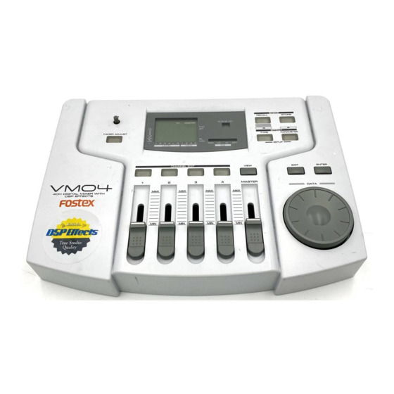
- Page 1 FOSTEX CORPORATION 3-2-35 Musashino, Akishima, Tokyo, Japan 196-0021 FOSTEX CORPORATION OF AMERICA 15431 Blackburn Ave., Norwalk, CA 90650, U.S.A. © PRINTED IN JAPAN MAR 1999 8288778000 Service Manual Model VM04 4ch Digital Mixer with DSP Effects...
- Page 2 VM04 CAUTION RISK OF ELECTRIC SHOCK DO NOT OPEN CAUTION: TO REDUCE THE RISK OF ELECTRIC SHOCK, DO NOT REMOVE COVER (OR BACK). NO USER-SERVICEABLE PARTS INSIDE. REFER SERVICING TO QUALIFIED SERVICE PERSONNEL. The lightening flash with arrowhead symbol, within an equilateral triangle, is intended to alert the user to the presence of uninsulated “dangerous voltage”...
-
Page 3: Table Of Contents
* Parts List and circuit diagrams are given in this manual to assist the service technician in maintaining the Model VM04 * The following accessories are supplied with VM04 as the standard accessories. * Following is the packing material for the Model VM04. -
Page 4: Specifications
VM04 1. SPECIFICATIONS DEFINITION (Specification Unit : 0 dBV = 1 Vrms) NORMAL FADER POSITION Master fader ... 80 position (Master Fader display) Input fader ... 80 position (Channel Fader display) Effect Send ... 00 position MIXER SECTION INPUT 1, 2 Input Level ... -
Page 5: Controls, Indicators And Connectors
VM04 2. CONTROLS, INDICATORS AND CONNECTORS < REAR PANEL > 1 2 3 RESET DC IN S/P DIF FOOT SW PHONES OUTPUT DC INLET connector [the Center Positive] Stereo OUTPUT L/R jacks [Ø6 mm Phone] S/P DIF optical output connector [Optical] RESET switch FOOT SW (unlatched) jack [Ø6 mm Phone]... -
Page 6: Service Mode
Software Version Check While holding down the EXIT key and ENTER key together, press the EFFECT TYPE key. The LCD Display will show the Software Version of the VM04 for a second, and then return to the Normal Mix mode. -
Page 7: Replacing The Battery
VM04 DZF2 DZF1 AOUTR2 AOUTL2 AOUTR1 AOUTL1 VRDAL AVSS AVDD VRDAH AINR- AINR+ AINL- AINL+ VCOM VRADL AVSS AVDD VRADH DVDD DVSS /RASCE /CASRF DRDY WRDY SCLK DVDD DVSS /WRQ TSTI2 Memory Clear While holding down the EXIT key and ENTER key together, press the SCENE STORE key ·... -
Page 8: Exploded View
VM04 4. EXPLODED VIEW B 3x8 BTT 3x8 BZn BTT 3x8 BTT 3x8 BTT 3x8 BZn BTT 3x8 BTT 3x8 BZn DZF2 DVDD DZF1 DVSS AOUTR2 AOUTL2 AOUTR1 AOUTL1 VRDAL AVSS AVDD /RASCE VRDAH /CASRF AINR- DRDY AINR+ WRDY AINL-... -
Page 9: Parts List
IC, ST, DG, DRIVER, DTC114EK R109, 209 8230500103 U003 8236541300 IC, ST, AN, DC-DC, NJM2360AM R110, 210 8240154010 U004 8236085201 IC, QFP, DG, CPU, VM04 R111, 211 8230500104 U005 8236545014 IC, ST, TSSOP, 74VHC14 R112, 212 8230500104 U006, 007 8236084900... - Page 10 VM04 CAPACITORs 8274165000 PCB ASSY, DISPLAY, VM04 ALU = Electrolytic CER = Ceramic type Ref.No. Ref.No. Part No. Description U301 C026~029 8233504103 ST, CER, 25V, 0.01 F, 10% U302 C031 8232143106 VT, ALU, 16V, 10 F, 20% C032~037 8233504103 ST, CER, 25V, 0.01 F, 10%...
-
Page 11: Pcb Pattern Drawing
R214 L111 R215 R114 R402 R401 L401 R115 R131 D306 S306 S309 D305 S308 S311 D304 S307 S310 8251972 MAIN, VM04 C70 C69 C48 C47 C307 R304 R104 R204 C306 C206 C203 C103 C303 C201 C101 L201 L101 C205 R302... - Page 12 R102 R202 L301 C105 C205 R201 L101 L201 C101 C201 C203 C103 C106 C306 C206 R104 R204 R304 VM04 MAIN, 8251972 DISPLAY PCB : PARTS SIDE U302 R311 L301 D351 S301 D352 D353 S302 J301 (LCD) R115 R301 R302 L401...