Table of Contents
Advertisement
Quick Links
Advertisement
Table of Contents

Related Manuals for JRC AlphaWind AlphaLine Series


Summary of Contents for JRC AlphaWind AlphaLine Series
- Page 1 AlphaWind Wind Repeater Installation and Operation Manual www.jrc.am...
-
Page 2: Table Of Contents
Contents I Preface......................4 I.1 Revision History................................ 4 I.2 Glossary..................................4 I.2.1 Definitions................................. 4 I.2.2 Abbreviations..............................5 I.3 Norms and Standards............................... 6 II Warnings and Cautions................7 II.1 Warranty................................... 8 II.2 Storage..................................8 III Introduction....................9 1 Installation Instructions................10 1.1 Mechanical Installation............................ - Page 3 2.5.1.1 Generic Settings Menu........................31 2.5.1.2 Touch Screen Calibration (TOUCH CAL).................... 32 2.5.1.3 Cleaning Display ( CLEAN MODE )....................33 2.5.1.4 Change Theme (THEME)........................34 2.5.1.5 Change Date and Time (DATE/TIME)....................34 2.5.1.6 About the AlphaLine instrument (ABOUT)...................36 2.5.1.7 Change Range Settings (RANGE SCALE)..................37 2.5.1.8 Unit Selection (UNITS).........................38 2.5.1.9 Wind Settings (WIND SET)........................38 2.5.2 Advanced Settings............................
-
Page 4: I Preface
I Preface The Alphatron Marine AlphaLine instrument range was designed for navigation and control of ships and is based on generic hardware and software, allowing for many different applications. • Thoroughly read this instruction manual before installation and operation of the equipment. •... -
Page 5: Abbreviations
CAN bus Controller Area Network. This is a network based serial bus system used for exchanging information. It is the advanced version of RS485/422 serial buses. Reverse polarity protection This is a part of the power supply hardware that prevents any damage to the equipment when the power supply is connected to the wrong polarity. -
Page 6: Norms And Standards
Remote Control Unit Rate Of Turn Volts Alternating Current Volts Direct Current Voyage Data Recorder Watt Table 2: Abbreviations I.3 Norms and Standards The AlphaWind complies with the applicable standards, norms and regulations: • IEC 60945 (2002) including IEC 60945 Corrigendum 1 (2008) •... -
Page 7: Warnings And Cautions
II Warnings and Cautions The signal words WARNING and CAUTION used in this manual indicate the degree of hazard that may be encountered by the user. These words are defined as: • WARNING • A WARNING indicates potential risk of injury or death to users of the product. •... -
Page 8: Ii.1 Warranty
• CAUTION • If the instruments are not stored as described, it will void the warranty. • CAUTION • When cleaning the surface, do not use any organic solvent such as thinner or benzine. Otherwise, the paint and markings on the surface may get damaged. For cleaning the surface, remove the dust and debris and wipe with a clean dry cloth. -
Page 9: Introduction
III Introduction Each type in this navigation and control instrument product range consists of a display unit and, if applicable, one or more external remote I/O modules. The following display sizes are available for your AlphaLine instrument: AlphaLine MFM 6.5 inch display LCD orientation vertical AlphaLine MFL 8.4 inch display... -
Page 10: Installation Instructions
1 Installation Instructions Installation follows a generic method and is applicable to the complete range of AlphaLine instruments. This chapter describes the installation into a console. 1.1 Mechanical Installation • CAUTION • This product must be installed in accordance with the installation methods described in this manual. Acting otherwise will void the warranty. -
Page 11: Fitting Instrument Mounting Frame
1.1.4 Fitting Instrument Mounting Frame Prior to fitting the display unit, install the mounting frame. Figure 2: Mounting Frame MFM Figure 3: Mounting Frame MFL 1. Make a square hole in the (overhead) console. Use the provided template. For dimensions, see Mechanical Drawing MFM on page 56 or Mechanical Drawing MFL on page 57. - Page 12 Figure 4: IP56 Kit for MFM The IP56 Kit for MFL consists of the following items: • 1 gasket MFS • 4 adapters M3-M6 • 4 lock washers M6 • 4 hex nuts M6 Figure 5: IP56 Kit for MFL Mounting instructions: Remove the 4 snaps ( ) from the instrument.
-
Page 13: Instrument Electric Connections
INFO: Pay special attention to the small protruding cam, so that it fits exactly in the gap in the front panel. 5. Place the instrument in the bracket. 6. Mount the 4 lock washers and hex nuts. 1.1.6 Instrument Electric Connections All AlphaLine instrument versions share the same electronics with identical connections. -
Page 14: Cable Preparation Receiving Sides
Figure 6: Cable Preparation Sending Cable Sides Note Always check the drawing for the correct shielding of signals. 1.1.8.2 Cable Preparation Receiving Sides 1. Remove approx. 80 mm of the plastic cable sheath, including the grounding shield. 2. Wrap insulating tape over the cable end. 3. -
Page 15: Instrument Power Supply
Figure 8: Grounding Bolt Note The grounding strap must be as short as possible. If wire is used, use a minimum of 2.5 mm copper wire. See Figure 8: Grounding Bolt on page 15. Note Always check the drawing for the correct shielding of signals. 1.1.10 Instrument Power Supply The AlphaLine instrument has one 24 VDC (nominal) power input. -
Page 16: Serial Interfaces
1.1.11 Serial Interfaces This chapter provides extra information about the serial interfaces used in the Marine Electronics. • IEC 61162-1 This standard is the most commonly used. In the standard, the sender (Tx side) and receiver (Rx side) are referred to as talker and listener. -
Page 17: Serial Connection
Figure 10: IEC 61162-2 Circuits The main difference with the IEC 61162-1 standard is that a COMMON signal is added here for a good reference to isolated ground. • Tx+ and Tx– are connected to Rx+ and Rx– respectively. • The shield of the cable is connected to the earth on the transmitting side, and is NOT connected on the listener. -
Page 18: Relay
For pin connections, see Figure 12: Serial pin connections on page 18, Table 4: Serial Connector P12 (8 pins) on page 18 and Table 5: Serial Connector P19 (12 pins) on page 18. Figure 12: Serial pin connections COM0 IEC 61162-2 Tx+ COM1 IEC 61162-1 Tx+ COM0 IEC 61162-2 Tx–... -
Page 19: Connecting Serial Ports
Relay Normally Open Relay Common Relay Normally Closed Table 6: Relay Connector P12 (8 pins) 1.1.14 Connecting Serial Ports Serial data from sensors such as GPS, Speedlog and others is commonly known as NMEA. In the regulations is referred to the IEC standard for the correct protocol description. These are IEC 61162-1 and IEC 61162-2. The manual will use both these standards as there is a difference between them. -
Page 20: Connecting Dimmer
1.1.15 Connecting Dimmer AlphaLine instruments can accept IEC 61162-1 dimmer messages with the $--DDC format. Connect the signal to the designated dimmer connector as shown on the connection diagram, see Electric Diagrams on page 58. Figure 13: Dimmer Message 20 | Installation Instructions... -
Page 21: Software Installation
1.2 Software Installation The software version for this AlphaLine instrument is 1.X. 1.2.1 Selecting Active Software The AlphaLine instrument is stocked in the warehouse with all software pre-installed. The commissioning engineer will select the function the AlphaLine instrument requires. When a AlphaLine instrument is started up for the first time, or after a RESET, a selection menu appears where the required application can be selected. -
Page 22: Software Updates
Visit our support website www.jrc.am/support for the newest manuals and to check that your product is still running the latest software. Due to the nature of our products and solutions, software and relevant instructions will be available to authorized distributors and dealers only. -
Page 23: Operation
2 Operation 2.1 Power The unit must be connected to the power at all times. • Use the power button in the front panel of the instrument to switch the power ON and OFF. Note In the OFF position, the power button is still dimly lit for easy identification in the dark. This only applies when the instrument is connected to the power supply. -
Page 24: True Wind Versus Relative Wind
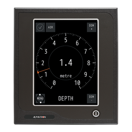
Figure 17: Main Screen AlphaWind Fore Figure 18: Main Screen AlphaWind Aft Functionality of the buttons is as described in table below. Shows the instrument is functioning normally. If there's a malfunction a colored alert symbol will show here. Opens the MENU, where settings can be adjusted. This button also shows the functionality of the instrument by rotating. - Page 25 Figure 19: Menu Example Go to main screen. Touch again to go to MENU. Go back to the previous screen without saving settings. Undo the last value change. Accept and save current settings and applied settings will be saved. Undo all settings and exit MENU Normal condition, meaning there is no alarm.
-
Page 26: Default Values Alphaline Instrument
2.3.1 Default Values AlphaLine Instrument When the AlphaWind is reset, it will return to the start-up screen, where a new instrument can be selected. The newly selected instrument will contain the default values. The default values for the AlphaWind are shown in the table below. Menu ->... -
Page 27: Alert Handling
Menu -> ADV_SET -> UART Config [2/2] Data Bits Baud Rate 4800 Protocol NMEA Menu -> ADV_SET -> NMEA_FILTER ID 1: Sentence ID 2: Sentence Menu -> ADV_SET -> NMEA_TALKER TALKER USED / UNUSED USED Menu -> ADV_SET -> Wind_Set FILTER (s) Menu ->ADV_SET ->NMEA_SET SENTENCE... - Page 28 Figure 20: Alert Handling in Main Screen (example) For alert handling while operating the MENU, see Figure 21: Alert Handling in Menu (example) on page 29. 28 | Operation...
- Page 29 Figure 21: Alert Handling in Menu (example) 29 | Operation...
- Page 30 Icon Icon Name Icon Description Icon Graphic Number Normal Condition Stationary circle with gray tick mark Active - Flashing red triangle with loudspeaker and alert text. Unacknowledged Alarm Touching this icon toggles the visibility of the alert text. Active - Acknowledged Red triangle with exclamation mark and alert text.
-
Page 31: Settings
2.5 Settings All instruments have generic and advanced settings. All users are authorized to use the generic settings. Only the commissioning engineer has access to the advanced settings, which are only needed during commissioning or troubleshooting. 2.5.1 Generic Settings Every user of the AlphaLine instrument can access the generic settings. 2.5.1.1 Generic Settings Menu Touch the MENU button in the main screen to enter the MENU with generic settings, see Figure 22: Generic Settings Menu on page 31 . -
Page 32: Touch Screen Calibration (Touch Cal)
2.5.1.2 Touch Screen Calibration (TOUCH CAL) The touch screen can be calibrated by following the instructions that appear on the screen. Figure 23: Touch Screen Calibration Figure 24: Calibration Reference Figure 25: Calibration Lines Menu Points 1. In the MENU, touch the TOUCH CAL button. The TOUCH SCREEN CALIBRATION MENU appears, see Figure 23: Touch Screen Calibration Menu on page 2. -
Page 33: Cleaning Display ( Clean Mode )
2.5.1.3 Cleaning Display ( CLEAN MODE ) The purpose of CLEAN MODE is to clean the surface of the display unit without accidentally activating a function. When the CLEAN MODE is started, the touch screen will be deactivated for 60 seconds. Within this period the instrument will remain functional, but it is not operable. -
Page 34: Change Theme (Theme)
2.5.1.4 Change Theme (THEME) 2.5.1.4.1 Change Illumination Contrast brightness can be easily adjusted to Day, Dusk and Night settings. Figure 28: Theme 1. In the MENU, touch the THEME button. The THEME MENU appears, see Figure 28: Theme on page 34 . 2. - Page 35 Figure 29: Date/Time Screen 1 Figure 30: Date/Time Screen 2 1. In the SETTINGS screen, touch the DATE/TIME button. The DATE/TIME screen appears, see Figure 29: Date/Time Screen 1 on page 35. 2. Touch the + and – buttons to set the correct DATE values. 3.
-
Page 36: About The Alphaline Instrument (About)
2.5.1.6 About the AlphaLine instrument (ABOUT) The ABOUT screen contains the name and version of the software and when it was built. Figure 31: About the Alphaline Instrument (example) 1. In the MENU, touch the ABOUT button. The ABOUT MENU appears, see for example Figure 31: About the Alphaline Instrument (example) on page 36. Note When asking for manufacturer's support, this information will be useful. -
Page 37: Change Range Settings (Range Scale)
2.5.1.7 Change Range Settings (RANGE SCALE) There are various options for RANGE SETTINGS depending on which instrument is being used. With the ALARM option, an alarm above a certain speed can be set. For example, when it is set to 6, a new alarm is triggered (buzzer and audible) when the wind speed is above 6 Beaufort. Figure 32: Range Settings AlphaWind 1. -
Page 38: Unit Selection (Units)
2.5.1.8 Unit Selection (UNITS) The UNITS menu enables selection of unit to represent the displayed value. Figure 33: Units Menu 1. In the MENU, touch the UNITS button. The UNITS MENU appears, see Figure 33: Units Menu on page 38. 2. -
Page 39: Advanced Settings
Figure 34: Wind Settings Menu 1. In the MENU, touch the WIND SET button. The WIND SETTINGS MENU appears, see Figure 34: Wind Settings Menu on page 39. 2. Touch either the + or – button to enable or disable the WIND FILTER. 3. - Page 40 Figure 36: Advanced Settings Menu 1. In the MENU, touch the ADV SET button. The PASSWORD screen appears, see Figure 35: Password Screen on page 39. 2. Key in the password and confirm with the √ button. The ADVANCED SETTINGS MENU appears, see Figure 36: Advanced Settings Menu on page 40 . 3.
-
Page 41: Central Dimming (Cntrl Dim)
2.5.2.2 Central Dimming (CNTRL DIM) The AlphaLine instrument supports central dimming as a listener (slave) from a standard (IEC 61162-1) dimming sentence. This dimming signal should be connected to serial port COM3, see Table 5: Serial Connector P19 (12 pins) on page 18. Also see Figure 12: Serial pin connections on page 18. -
Page 42: Ethernet Configuration (Eth Config)
2.5.2.3 Ethernet Configuration (ETH CONFIG) The AlphaLine instrument has one network interface to connect to a ship's network. This can be useful when the instrument is connected to a remote interface or a PLC which uses Modbus/TCP. The Ethernet interface can also be used for IEC 611612-450 signals. Note This option has been included for future use. -
Page 43: Serial Port Configuration (Uart Config)
2.5.2.4 Serial Port Configuration (UART CONFIG) The AlphaLine instrument is equipped with 4 serial ports (also called UART or COM). The settings of the serial ports are divided over two screens as shown in Figure 40: UART Screen 1 on page 43 and Figure 41: UART Screen 2 on page 43. -
Page 44: Nmea Filter (Nmea Filter)
2.5.2.5 NMEA Filter (NMEA FILTER) This filter is included to select the correct sentence where several sentence options are possible for the same function. There are 2 circumstances where such situation can occur: 1. A single sensor which produces different NMEA sentences with the same value. 2. - Page 45 Figure 43: Serial Port 1 Figure 44: Serial Port 3 1. In the MENU, touch the ADV SET button. The PASSWORD screen appears. 2. Key in the password and confirm with the √ button. The ADVANCED SETTINGS MENU appears. 3. Touch the SERIAL MON button. The SERIAL PORT MONITOR 1 screen appears, see Figure 43: Serial Port 1 on page 45.
-
Page 46: Factory Reset (Reset)
2.5.2.7 Factory Reset (RESET) All menu settings can be reset to the factory default setting. For an overview of the default settings, see Default Values AlphaLine Instrument on page 26. Figure 45: Execute Factory Reset Figure 46: First Start-Up Screen 1. -
Page 47: Log (Log)
4. Touch the ˅ or ˄ buttons to scroll through the readings. 5. Take a picture of the log screen and contact the Alphatron Service Desk at www.jrc.am/support about errors. Note Use for example a mobile phone to take a picture. -
Page 48: Nmea Talker (Nmea Talker)
2.5.2.9 NMEA Talker (NMEA TALKER) With this menu, some additional NMEA sentence filters can be applied on the address field of an NMEA sentence. The address field consists of a talker ID and a sentence formatter (for example ROT). This is depending on the configuration of the software. -
Page 49: Wind Settings (Wind Set)
2.5.2.10 Wind Settings (WIND SET) The Filter in Wind Settings is designed to dampen fluctuations in wind speed and direction depending on weather conditions and location of the wind sensor. Wind Settings allows for fine tuning the Wind Sensor. To make the appearance of the direction indication on the display calmer, a filter can be applied to the wind direction. The value of the Filter determines the stability on the display. - Page 50 Figure 50: NMEA OUTPUT 1. In the MENU, touch the ADV SET button. The PASSWORD screen appears. 2. Key in the password and confirm with the √ button. The ADVANCED SETTINGS MENU appears. 3. Touch the NMEA SET button. The NMEA OUTPUT MENU appears, see Figure 50: NMEA OUTPUT on page 50 •...
-
Page 51: Maintenance
3 Maintenance • CAUTION • This product contains no operator serviceable parts. Service and repair shall only be carried out by personnel trained and certified by ALPHATRON MARINE. • CAUTION • When cleaning the surface, do not use any organic solvent such as thinner or benzine. Otherwise, the paint and markings on the surface may get damaged. - Page 52 4 Appendix A Appendix A contains: 1. Hardware Specifications on page 53 2. Mechanical Drawings on page 56 3. Electric Diagrams on page 58 4. Schematics on page 61 52 | Appendix A...
-
Page 53: Hardware Specifications
4.1 Hardware Specifications 4.1.1 Specifications MFM Box Contents upon Delivery Display Functionality AlphaLine MFM 3803.0242 gray / 3803.0244 black Font display text 7 mm (viewing distance = 2 m) Mounting bracket Font operation buttons 3.5 mm (viewing distance = 1 m) Screws (4 pcs) Accuracy Resolution 0.1°/min... -
Page 54: Specifications Mfl
4.1.2 Specifications MFL Box Contents upon Delivery Display Functionality AlphaLine MFL 3803.0246 grey / 3803.0248 black Font display text 7 mm (viewing distance = 2 m) Mounting bracket Font operation buttons 3.5 mm (viewing distance = 1 m) Screws (4 pcs) Accuracy Resolution 0.1°/min USB flash drive with manuals... -
Page 55: Software Specifications
4.2 Software Specifications 4.2.1 Supported NMEA Sentences IEC 61162 Supported NMEA sentences (IEC 61162) Primary IN $xxHDT Primary IN $xxMWV Primary IN $xxVTG Secondary IN $xxDDC Secondary IN $xxTHS Secondary IN $xxRMA Secondary IN $xxRMC Secondary OUT $VDDDC Table 15: Supported NMEA Sentences 4.2.2 Alert List Alert list Invalid checksum of NMEA ... -
Page 56: Mechanical Drawings
4.3 Mechanical Drawings 4.3.1 Mechanical Drawing MFM Figure 51: Mechanical Drawing MFM 56 | Appendix A... -
Page 57: Mechanical Drawing Mfl
4.3.2 Mechanical Drawing MFL Figure 52: Mechanical Drawing MFL 57 | Appendix A... -
Page 58: Electric Diagrams
4.4 Electric Diagrams The cable diagrams and connection diagrams illustrate the connections to hardware, power and other equipment. 4.4.1 Cable Diagram AlphaWind Figure 53: Cable Diagram AlphaWind 58 | Appendix A... -
Page 59: Connection Diagram Alphawind
4.4.2 Connection Diagram AlphaWind Figure 54: Connection Diagram AlphaWind 1 59 | Appendix A... - Page 60 Figure 55: Connection Diagram AlphaWind 2 60 | Appendix A...
-
Page 61: Schematics
4.5 Schematics This chapter contains the schematics of the AlphaLine instruments. The commissioning engineer uses the schematics to be able to connect the signals according to the ship's requirements. 61 | Appendix A... -
Page 62: Schematics Alphaline Mf Display Unit
4.5.1 Schematics AlphaLine MF Display Unit Figure 56: Schematics AlphaLine MF Display Unit 62 | Appendix A... -
Page 63: Schematics Alphaline Instrument
4.5.2 Schematics AlphaLine Instrument Figure 57: Schematics AlphaLine Instrument 63 | Appendix A... - Page 64 All over the world, close to the customer JRC/Alphatron Marine Schaardijk 23 (harbor 115) The information in this document is subject to change without notice and 3063 NH Rotterdam does not represent a commitment on the part of Alphatron Marine B.V.