Table of Contents
Advertisement
Quick Links
Advertisement
Table of Contents

Related Manuals for Toro 03708


Summary of Contents for Toro 03708
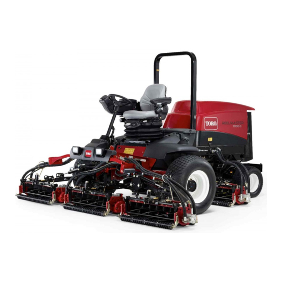
- Page 1 Form No. 3376-315 Rev D Reelmaster ® 7000-D 4-Wheel Drive Traction Unit Model No. 03708—Serial No. 313000001 and Up To register your product or download an Operator's Manual or Parts Catalog at no charge, go to www.Toro.com. Original Instructions (EN)
-
Page 2: Introduction
Genuine Toro spark arresters are approved by the USDA Forestry Service. Important: This engine is equipped with a spark arrester muffler. -
Page 3: Table Of Contents
Safety ................4 Engine Maintenance..........41 Safe Operating Practices ........4 Servicing the Air Cleaner ........41 Toro Riding Mower Safety ........6 Servicing the Engine Oil and Filter...... 42 Sound Power Level..........7 Adjusting the Throttle ........42 Sound Pressure Level ........... 7 Fuel System Maintenance ........ -
Page 4: Safety
Safety ◊ incorrect hitching and load distribution. • The owner/user can prevent and is responsible for accidents or injuries occurring to himself or herself, This machine meets or exceeds CEN standard EN other people, or property. 836:1997 (when appropriate decals applied), and ANSI B71.4-2004 specifications in effect at the time of Preparation production. - Page 5 – machine speeds should be kept low on slopes • Look behind and down before backing up to be sure and during tight turns; of a clear path. • Slow down and use caution when making turns and – stay alert for humps and hollows and other hidden hazards;...
-
Page 6: Toro Riding Mower Safety
The following list contains safety information specific increases. Steep hills should be avoided. to Toro products or other safety information that you Cutting units must be lowered when going down must know that is not included in the CEN, ISO, or slopes to maintain steering control ANSI standard. -
Page 7: Sound Power Level
EN 836. • To ensure safety and accuracy, have an Authorized Vibration Level Toro Distributor check the maximum engine speed with a tachometer. Hand-Arm • If major repairs are ever needed or if assistance is desired, contact an Authorized Toro Distributor. - Page 8 117-4765 1. Read the Operator's Manual. 2. Do not use starting aids. 117–2385 1. Read the Operators 3. Engine—preheat Manual. 2. Engine—start 4. Engine—stop 117-4766 1. Cutting/dismemberment hazard; fan—stay away from moving parts. 117–2718 117-2386 1. Raise deck 3. Reverse 2.
- Page 9 93-6688 110-9642 1. Warning—read the 2. Cutting hazard of hand or 1. Stored energy hazard—read the Operator's Manual. instructions before foot—stop the engine and servicing or performing wait for moving parts to 2. Move the cotter pin to the hole closest to the rod bracket maintenance.
- Page 10 120-1686 Affix over part no. 120–1683 for CE* *This safety decal includes a slope warning required on the machine fro compliance to the European Lawn Mower Standard EN 836.1997. The conservative maximum slope angles indicated for operation of this machine are prescribed by and required by this standard. 1.
- Page 11 Battery Symbols Some or all of these symbols are on your battery 1. Explosion hazard 6. Keep bystanders a safe distance from the battery. 2. No fire, open flame, or 7. Wear eye protection; smoking. explosive gases can cause blindness and other injuries 3.
-
Page 12: Setup
Setup Loose Parts Use the chart below to verify that all parts have been shipped. Procedure Description Qty. – No parts required Adjust the support rollers Used only on machines requiring CE Warning decal Compliance. Hood lock bracket Rivet Used only on machines requiring Screw, 1/4 x 2 inch European CE Compliance. -
Page 13: Adjusting The Support Rollers
Adjusting the Support Rollers Replacing the Warning Decal for CE Compliance No Parts Required Parts needed for this procedure: Procedure Warning decal Depending on what width cutting units are to be installed on the traction, adjust the support rollers as follows: Procedure •... - Page 14 G012629 Figure 6 1. CE lock bracket 2. Bolt and nut assembly 4. Align the washers with the holes on the inside of the Figure 4 hood. 1. Hood latch 5. Rivet the brackets and the washers to the hood (Figure 6).
-
Page 15: Installing The Cutting Units
Installing the Cutting Units Parts needed for this procedure: Figure 10 1. Turf compensation spring 3. Spring tube Front hose guide-R.H. 2. Rod bracket Front hose guide-L.H. B. Remove the flange nut securing the spring tube Procedure bolt to the carrier frame tab (Figure 10) Remove the assembly. - Page 16 Figure 13 1. Hose guide (Left hand 3. Nuts shown) 2. Rod bracket g019602 Figure 14 1. Hose guides (each must lean toward the center cutting unit) Note: When installing or removing the cutting units, make sure the hairpin cotter is installed in the spring rod hole next to the rod bracket.
- Page 17 9. For the front cutting units, slide a cutting unit under the lift arm while inserting the carrier frame shaft up into the lift arm pivot yoke (Figure 16). Make sure the thrust washer is in position on the carrier frame shaft.
-
Page 18: Adjusting The Turf Compensation Spring
13. Secure the lift arm chain to the chain bracket with the snapper pin (Figure 19). Use the number of chain links described in the cutting unit Operator's Manual. Adjusting the Turf Compensation Spring No Parts Required Procedure The turf compensation spring (Figure 21) transfers weight from the front to the rear roller. -
Page 19: Using The Cutting Unit Kickstand
Using the Cutting Unit Kickstand Parts needed for this procedure: Cutting unit kickstand Procedure Whenever the cutting unit has to be tipped to expose the bedknife/reel, prop up the rear of the cutting unit with the kickstand to make sure the nuts on the back Figure 23 end of the bedbar adjusting screws are not resting on the work surface (Figure 22). -
Page 20: Using The Gauge Bar
Product Overview 2. Check the hydraulic fluid level before the engine is first started, refer to Checking the Hydraulic Fluid Level in Operation. Controls 3. Check the engine oil level before and after the engine is first started, refer to Checking the Engine Oil Brake Pedals Level in Operation. - Page 21 Charge Indicator toward you to the most comfortable position and then release the pedal. The charge indicator (Figure 27) illuminates when the system charging circuit malfunctions. Mow Speed Limiter Key Switch When the mow speed limiter (Figure 26) is flipped up it will control the mow speed and allow the cutting units The key switch (Figure 27) has three positions: Off, to be engaged.
- Page 22 the machine, with the cutting units in the down position, has two positions R (manual reverse) and Auto (normal). press the lift switch down to allow the cutting units to Refer to Engine Cooling Fan Operation in the Operation float and mow. Section of manual.
- Page 23 Weight gauge Indicates when the seat is adjusted to the weight of the operator (Figure 32). Height adjustment is made by positioning the suspension within the range of the green region. Figure 30 1. Reel speed controls Fuel Gauge Figure 32 1.
-
Page 24: Specifications
A selection of Toro approved attachments and accessories is available for use with the machine to enhance and expand its capabilities. Contact your Authorized Service Dealer or Distributor or go to www.Toro.com for a list of all approved attachments and accessories. -
Page 25: Operation
• Preferred oil: SAE 15W-40 (above 0°F) • Alternate oil: SAE 10W-30 or 5W-30 (all temperatures) Figure 34 Note: Toro Premium Engine oil is available from your distributor in either 15W-40 or 10W-30 1. Dipstick viscosity. See the parts catalog for part numbers. -
Page 26: Checking The Cooling System
Figure 35 1. Oil fill cap Note: When using different oil, drain all old oil from the crankcase before adding new oil. Figure 36 5. Install the oil fill cap and dipstick. 1. Expansion tank 6. Close the hood and secure it with the latches. 2. - Page 27 WARNING DANGER Fuel is harmful or fatal if swallowed. Long-term In certain conditions, fuel is extremely flammable exposure to vapors can cause serious injury and and highly explosive. A fire or explosion from fuel illness. can burn you and others and can damage property. •...
-
Page 28: Checking The Hydraulic Fluid Level
(Available in 5 gallon pails or 55 gallon drums. See parts catalog or Toro distributor for part numbers.) Alternate fluids: If the Toro fluid is not available, other fluids may be used provided they meet all the following material properties and industry specifications. We do not recommend the use of synthetic fluid. -
Page 29: Checking The Tire Pressure
3. Remove the dipstick from the filler neck and wipe When the temperature is less than 20°F (-7°C), the it with a clean rag. Insert the dipstick into the filler starter motor can be run for 30 seconds on then 60 neck;... -
Page 30: Setting The Reel Speed
pedal is released, it is strongly recommended that the neutral position. The engine should kill. If the engine be stopped before rising from the seat. engine does not kill, there is a malfunction in the interlock system that should be corrected before To check the operation of the interlock switches, beginning operation. -
Page 31: Adjusting The Lift Arm Counterbalance
Figure 41 1. Spring 2. Spring actuator 4. Move the spring actuator to the desired hole Figure 40 location and secure with locknut. 1. Reel speed control knob 5. Repeat the procedure on the remaining spring. Adjusting the Lift Arm Turn Adjusting the Lift Arm Around Position Counterbalance... -
Page 32: Pushing Or Towing The Machine
Jacking Points turn around height or move the switch down to decrease the lift arm turn around height. Tighten • On the front of the machine on the frame on the the mounting screws. inside of each drive tire • On the rear of the machine at the center of the axle Pushing or Towing the Machine Tie Downs... -
Page 33: Diagnostic Ace Display
Verifying the Interlock Switch Function If the diagnostic light is not illuminated when the key switch is in the On position, this indicates that the 1. Park the machine on a level surface, lower the electronic controller is not operating. Possible causes cutting units, stop the engine, and engage the are as follows: parking brake. -
Page 34: Operating Characteristics
ECM problem. If the switch and/or check the switches with an ohm this occurs, contact your Toro Distributor for assistance. meter. Replace any defective switches and repair Important: The Diagnostic ACE display must any defective wiring. -
Page 35: Engine Cooling Fan Operation
Warning System brakes can be used to assist in turning the machine. However, use them carefully, especially on soft or If a warning light comes on during operation, stop the wet grass because the turf may be torn accidentally. machine immediately and correct the problem before Another benefit of the brakes is to maintain traction. -
Page 36: Maintenance
Maintenance Note: Determine the left and right sides of the machine from the normal operating position. Recommended Maintenance Schedule(s) Maintenance Service Maintenance Procedure Interval • Torque the wheel nuts. After the first 8 hours • Change the engine oil and filter. After the first 50 hours •... -
Page 37: Daily Maintenance Checklist
Daily Maintenance Checklist Duplicate this page for routine use. Maintenance For the week of: Check Item Mon. Tues. Wed. Thurs. Fri. Sat. Sun. Check the safety interlock operation Check the brake operation Check the engine oil and fuel level Check the cooling system fluid level Drain the water/fuel... -
Page 38: Service Interval Chart
Service Interval Chart Figure 47 CAUTION If you leave the key in the ignition switch, someone could accidently start the engine and seriously injure you or other bystanders. Remove the key from the ignition before you do any maintenance. -
Page 39: Premaintenance Procedures
Premaintenance Lubrication Procedures Greasing the Bearings and Bushings Removing the Hood Service Interval: Every 50 hours 1. Release hood latches (Figure 48) and pivot open the hood. The machine has grease fittings that must be lubricated regularly with No. 2 General Purpose Lithium Base Grease. - Page 40 • Steering cylinder ball joints (2) (Figure 51) • Cutting unit carrier frame (2 per cutting unit) (Figure 53) • Cutting unit lift arm pivot (1 per cutting unit) (Figure 53) Figure 53 Figure 51 1. Top fitting on king pin •...
-
Page 41: Engine Maintenance
Engine Maintenance which could force dirt through the filter into the intake tract. This cleaning process prevents debris from migrating Servicing the Air Cleaner into the intake when the primary filter is removed. Service Interval: Every 400 hours 3. Remove and replace the primary filter (Figure 56). Check the air cleaner body for damage which could Cleaning of the used element is not recommended cause an air leak. -
Page 42: Servicing The Engine Oil And Filter
Servicing the Engine Oil and Adjusting the Throttle Filter Adjust the throttle cable (Figure 60) so that the governor lever on the engine contacts the high speed set bolt at Service Interval: After the first 50 hours the same point that the throttle cable contacts the end of Every 400 hours the slot in the control arm. -
Page 43: Fuel System Maintenance
Servicing the Water Separator Fuel System Maintenance Service Interval: Before each use or daily—Drain water or other contaminants from fuel filter/water separator. DANGER Every 400 hours—Replace the fuel Under certain conditions, diesel fuel and fuel filter canister. vapors are highly flammable and explosive. A fire or explosion from fuel can burn you and others and Drain water or other contaminants from water separator can cause property damage. -
Page 44: Bleeding Air From The Injectors
Bleeding Air from the Injectors Electrical System Maintenance Note: This procedure should be used only if the fuel system has been purged of air through normal priming procedures and the engine will not start. Charging and Connecting the 1. Loosen the pipe connection to the No. 1 injector Battery nozzle and holder assembly at the injection pump (Figure 62). -
Page 45: Battery Care
Battery posts, terminals, and related cable connectors with Grafo 112X (skin-over) grease accessories contain lead and lead compounds, (Toro Part No. 505-47) or petroleum jelly to prevent chemicals known to the State of California corrosion. to cause cancer and reproductive harm. -
Page 46: Fuses
Fuses The fuses are located under the operators control panel. TEC-5002 7.5A 7.5A 7.5A 120-1672 Figure 65 Figure 67 1. Fuses Unhook the latch and raise the operator's console panel (Figure 66) to expose the fuses (Figure 67). Figure 66 2. -
Page 47: Drive System Maintenance
Drive System 4. Re-install both plugs. 5. Repeat steps 1 through 4 on the opposite gear Maintenance assembly. Checking the Torque of the Changing the Planetary Gear Wheel Nuts Drive Oil Service Interval: After the first 8 hours Service Interval: After the first 200 hours Every 200 hours Every 800 hours (Or yearly, whichever comes first) -
Page 48: Checking The Rear Axle Lubricant
Changing the Rear Axle 4. When all of the oil has drained from both locations, re-install the plug in the brake housing. Lubricant 5. Rotate the wheel until the open plug hole in the Service Interval: After the first 200 hours planetary is at the twelve o'clock position. -
Page 49: Checking The Rear Wheel Toe-In
Figure 73 Figure 75 1. Pump rod jam nuts 2. Pump control tube 1. Tie rod clamp 2. Tie rod ball joint 5. After wheel rotation ceases, tighten jam nuts to 3. Loosen the clamps at both ends of the tie rods secure adjustment. -
Page 50: Cooling System Maintenance
Cooling System Maintenance Servicing the Engine Cooling System Service Interval: Before each use or daily Remove debris from the engine area, oil cooler and radiator daily. Clean them more frequently in dirty conditions. 1. Unlatch and swing open rear screen (Figure 76). Clean the screen thoroughly of all debris. -
Page 51: Brake Maintenance
Brake Maintenance Belt Maintenance Adjusting the Service Brakes Servicing the Alternator Belt Adjust the service brakes when there is more than 1 in. Service Interval: Every 100 hours (25 mm) of “free travel" of the brake pedal, or when the Check the condition and tension of the belts (Figure 80) brakes do not work effectively. -
Page 52: Hydraulic System Maintenance
Figure 82 every 800 operating hours, in normal conditions. 1. Hydraulic filter Use Toro replacement filters Part No. 94-2621 for the rear (cutting unit) of the machine and 75-1310 for the 4. Ensure that the filter mounting area is clean. Screw front (charge) of the machine. -
Page 53: Checking The Hydraulic Lines And Hoses
Checking the Hydraulic Lines Cutting Unit Maintenance and Hoses Backlapping the Cutting Units Service Interval: Before each use or daily Inspect the hydraulic lines and hoses daily for WARNING leaks, kinked lines, loose mounting supports, wear, Contact with the reels or other moving parts can loose fittings, weather deterioration, and chemical result in personal injury. -
Page 54: Cleaning
Off position after backlapping, the cutting units will not raise or function properly. Note: Additional instructions and procedures on backlapping are available in the TORO Sharpening Reel & Rotary Mowers Manual Form No. 80–300SL. Note: For a better cutting edge, run a file across the front face of the bedknife after lapping. -
Page 55: Storage
B. Clean the battery, terminals, and posts with a wire brush and baking soda solution. C. Coat the cable terminals and battery posts with Grafo 112X skin-over grease (Toro Part No. 505-47) or petroleum jelly to prevent corrosion. D. Slowly recharge the battery every 60 days for 24... -
Page 56: Schematics
Schematics Hydraulic Schematic (Rev. A) - Page 57 Electrical Schematic-Sheet 1 (Rev. C)
- Page 58 Electrical Schematic-Sheet 2 (Rev. C)
- Page 59 Notes:...
- Page 60 Countries Other than the United States or Canada Customers who have purchased Toro products exported from the United States or Canada should contact their Toro Distributor (Dealer) to obtain guarantee policies for your country, province, or state. If for any reason you are dissatisfied with your Distributor's service or have difficulty obtaining guarantee information, contact the Toro importer.