Advertisement
Safe Operation Practices • Set-Up • Operation • Maintenance • Service • Troubleshooting • Warranty
O
'
M
peratOr
s
anual
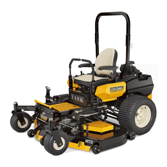
TANK M72
WARNING
READ AND FOLLOW ALL SAFETY RULES AND INSTRUCTIONS IN THIS MANUAL
BEFORE ATTEMPTING TO OPERATE THIS MACHINE.
FAILURE TO COMPLY WITH THESE INSTRUCTIONS MAY RESULT IN PERSONAL INJURY.
CUB CADET LLC, P.O. BOX 361131 CLEVELAND, OHIO 44136-0019
Printed In USA
Form No. 769-06675
(November 17, 2010)
Advertisement
Table of Contents

Related Manuals for Cub Cadet Tank M72


Summary of Contents for Cub Cadet Tank M72
- Page 1 READ AND FOLLOW ALL SAFETY RULES AND INSTRUCTIONS IN THIS MANUAL BEFORE ATTEMPTING TO OPERATE THIS MACHINE. FAILURE TO COMPLY WITH THESE INSTRUCTIONS MAY RESULT IN PERSONAL INJURY. CUB CADET LLC, P.O. BOX 361131 CLEVELAND, OHIO 44136-0019 Printed In USA Form No. 769-06675...
-
Page 2: Table Of Contents
Choose from the options below: ◊ Visit us on the web at www.cubcadet.com ◊ Locate your nearest Cub Cadet Dealer at (877) 282-8684 ◊ Write us at Cub Cadet LLC • P.O. Box 361131 • Cleveland, OH • 44136-0019... -
Page 3: Safe Operation Practices
Important Safe Operation Practices WARNING! This symbol points out important safety instructions which, if not followed, could endanger the personal safety and/or property of yourself and others. Read and follow all instructions in this manual before attempting to operate this machine. Failure to comply with these instructions may result in personal injury. - Page 4 Plan your mowing pattern to avoid discharge of material Do not attempt to mow through unusually tall, dry grass toward roads, sidewalks, bystanders and the like. Also, (e.g., pasture) or piles of dry leaves. Dry grass or leaves may avoid discharging material against a wall or obstruction contact the engine exhaust and/or build up on the mower which may cause discharged material to ricochet back deck presenting a potential fire hazard.
- Page 5 Use slow speed. Choose a low enough speed so that you ver allow children under 16 years of age to operate this machine. Children 16 and over should read and understand will not have to stop while on the slope. Avoid starting the instructions and safe operation practices in this manual or stopping on a slope.
- Page 6 Seat belts shall be used and shall be properly fastened The ROPS will not prevent the machine from upsets or roll about the operator’s waist at all times, except when the overs. ROPS or OPDs are: Only approved attachments should be used on this Not properly installed and/or not properly secured machine.
- Page 7 To avoid static discharge, keep the nozzle in contact Check the blade(s) and engine mounting bolts at frequent with the rim of the fuel tank or container opening intervals for proper tightness. Also, visually inspect blade(s) at all times until fueling is complete. Do not use a for damage (e.g., excessive wear, bent, cracked).
- Page 8 Safety Symbols This page depicts and describes safety symbols that may appear on this product. Read, understand, and follow all instructions on the machine before attempting to assemble and operate. Symbol Description READ THE OPERATOR’S MAnUAL(S) Read, understand, and follow all instructions in the manual(s) before attempting to assemble and operate WARnInG—...
- Page 9 2 — s ectiOn peratiOn ractices...
-
Page 10: Assembly & Set-Up
Assembly & Set-Up Contents of Crate • One Deck Wash Hose Coupler • One Lawn Tractor • One Tractor Operator’s Manual • One Engine Operator’s Manual Tractor Preparation Install Roll Over Protective System (ROPS) The Roll Over Protective System (ROPS) has not been installed Remove the upper crating material from the shipping pallet, and on your unit for shipping purposes. - Page 11 Install the upper ROPS section onto the lower ROPS “posts”. Move the upper ROPS section to the upright position, and Install the (1⁄2-13 x 3.25) HHCS bolts, nuts and washers. See insert the locking pins with their retainer hairpin clips. See Fig.
- Page 12 Adjusting Drive Control Levers To adjust the front-to-rear angle of the control levers: Loosen the nuts on the control lever mounting bolts, The RH and LH drive control levers can be adjusted up or down leaving the bottom one fairly snug. The top hole is slotted, and fore-and-aft for the comfort of the operator.
- Page 13 Connecting the Battery Cables CALIFORNIA PROPOSITION 65 WARNING! Battery posts, terminals, and related accessories contain lead and lead compounds, chemicals known to the State of California to cause cancer and reproductive harm. Wash hands after handling. CAUTION! When attaching battery cables, always connect the POSITIVE (Red) wire to its terminal first, followed by the nEGATIVE (Black) wire.
-
Page 14: Controls & Features
Controls & Features ROPS (Roll Over Protective System) WARNIN Fuel Shut-Off Valve Digital Tachometer & Hour Meter Choke Cup Holder Lever Switch Fuel Tank Cap Parking Brake RH Drive Control Lever LH Drive Control Lever Throttle Control Ignition Deck Height Switch Index Deck Lift... - Page 15 Ignition Switch Throttle Control The ignition switch is located on the RH console to the right of the operator’s seat. The ignition switch has three positions as follows: START The throttle control is located on the RH console to the right OFF - The engine and electrical system is of the operator’s seat.
- Page 16 Fuel Shut-Off Valve Transmission Bypass Valves (Not Shown) The fuel shut-off valve is located on top of the fuel tank(s). When The transmission bypass valves (one for each the RH and LH turned in a clockwise direction until it stops, it will shut off the transmission) are located just in front of the engine and just flow of fuel to the engine.
-
Page 17: Operation
Operation General Safety • Watch for holes, sprinkler heads, and other hidden hazards. • Avoid dr iving too close to trees, creeks, ditches, sand traps, • RECEIVE InSTRUCTIOn — Entirely read this operator’s and other obstacles. manual. Learn to operate this machine SAFELY. Do not risk •... - Page 18 If the interlock system should ever malfunction, do not operate the tractor. Contact your authorized Once the engine starts, push the choke on halfway and as Cub Cadet Dealer. the engine warms, push the choke off all the way. •...
- Page 19 Stopping the Engine Move the RH and LH drive control levers inward in the neutral position. Refer to Figure 5-2. Place the PTO switch in the “OFF” position. Move the RH and LH drive control levers fully outward in the neutral position. Engage the parking brake.
- Page 20 Driving the Tractor Forward To turn to the left, move the left drive control lever rearward of the right lever. See Fig. 5-4. WARNING! Keep all movement of the drive control levers slow and smooth. Abrupt movement of the control levers can affect the stability of the tractor and could cause the tractor to flip over, which may Forward Left Turn result in serious injury or death to the operator.
- Page 21 Driving the Tractor In Reverse Turning While Driving Rearward WARNING! To turn the tractor while driving rearward, move the control Always look behind and down on both levers as necessary so that one lever is forward of the other. The sides of the tractor before backing up.
- Page 22 Executing a Zero Turn Stopping the Tractor WARNING! Move both drive control levers to the neutral position to When executing a zero turn, the tractor stop the motion of the tractor. MUST BE STOPPED. Executing a zero turn while the tractor is moving can significantly reduce your Push the PTO switch downward to the disengaged control of the tractor and will cause severe turf...
- Page 23 If a safety circuit is not working as designed, of part numbers. contact you Cub Cadet dealer to have the tractor inspected. DO nOT operate the tractor if any safety circuit is not functioning properly. To check the safety circuits, proceed as follows: 5 —...
- Page 24 Reconfigurable Mower Inner Discharge Cutting Gauge Front Rear Front Skirt Baffle Baffle Blades Wheels Roller Rollers Low = 3 Low = 3 Low = 3 Standard set-up Installed Installed Hi-lift to 5” to 5” to 5” High = 1 to High = 1 to High = 1 to 2-1⁄2”...
-
Page 25: Maintenance & Adjustments
Maintenance & Adjustments Maintenance Schedule Before Every Every Every Every After Yearly Each use 25 Hours 50 Hours 100 Hours 500 Hours Mowing Check Hydraulic Hoses For Leaks Check Tires & Tire Pressure Check Deck, Mower And Hydro Drive Belts Check Blades And Blade Bolt Tightness Check Safety Switches For Proper Operation Check Fluid Level In Transaxle Expansion Reservoir... - Page 26 OIL CHART Apply a few drops of SAE engine oil, grease, or use a spray lubricant. Apply the oil to both sides of pivot points. Wipe off any excess. Start engine and operate mower briefly to insure that oil spreads evenly. number of Oil Points Description DAILY...
- Page 27 LUBRICATION CHART Use a grease-gun filled with nO. 2 Multipurpose Lithium Base Grease number of Grease Fittings Description EVERY 25 HOURS Blade Spindle Bearings WEEKLY Front Caster Wheels Front Caster Wheel Spindles Mower Deck Ball Wheels number of Grease Points Description WEEKLY Mowing Deck Pivots...
- Page 28 Warranty repairs must be performed by a Cub Cadet Dealer. Remove the hydraulic filter to allow hydraulic oil to drain. Remove the drain plug from the bottom of the hydraulic oil Hydraulic Oil tank to drain.
- Page 29 Place a small pan under the pump motor frame. Remove fill Fill the replacement filter with a good grade of 15W-40 oil oil cap from hydraulic reservoir for faster drainage. Remove and lubricate the sealing surface. nut caps and drain oil from both left and right pumps. Screw the filter onto the filter base until it seats and then Replace and retighten nuts.
- Page 30 • As a further precaution, only charge the battery in a well Loosen and remove the lug nuts and remove the ventilated area. wheel. • Always shield eyes and protect skin and clothing when Mount a wheel and tire, replace the lug nuts, and working near batteries.
- Page 31 Using the Transmission Bypass Valves Pull back the lock collar of the nozzle adapter and push the adapter onto one of the deck wash nozzles at either end of If for any reason the tractor will not drive or you wish to move the mower deck.
- Page 32 Battery Storage Emptying the fuel system: • Prior to putting the tractor in storage, monitor When storing the tractor for extended periods, disconnect fuel consumption with the goal of running the negative battery cable. It is not necessary to remove the fuel tank empty.
- Page 33 Start the engine and allow to idle for a few minutes to The right front blade tip height is fixed so you must adjust ensure engine is operating properly. the left front tip to match it. See Fig. 6-6. Drive the tractor without a load to make certain all the tractor systems are functioning properly.
- Page 34 Start at the rear right to raise the rear of the deck, tighten Remove the lock nut securing one of the front gauge wheel the rear outer jam nut to raise the deck or loosen the rear shoulder screws to the deck. Remove the gauge wheel and outer jam nut to lower the rear of the deck.
- Page 35 Adjusting the Front Skirt Removing/Installing the Inner Baffle The front skirt can be raised or lowered depending on the The inner flow-control baffle can be removed depending on mowing conditions. The skirt has three settings; low, medium the mowing conditions. The baffle controls discharge and can and high.
-
Page 36: Service
If you have a recurring problem with blown fuses, have the body with tools being used to connect the cables. tractor’s electrical system checked by your Cub Cadet Service Dealer. Charging the Battery... - Page 37 Seat Switch NOTE: There is a certain amount of spring tension due to the weight of the deck. When removing the lift linkage • With the speed control pedals in the neutral position, the from the deck the tension of the springs will go from the parking brake engaged and the PTO switch in the “OFF”...
- Page 38 Replacing the Blades Use a 1- 1⁄8” socket wrench on the pulley side of the spindle bolt. See Fig. 7-5. WARNING! Before performing any maintenance, place the PTO switch in the “OFF” position, engage Hex Screw the parking brake lever, turn the ignition key to the “OFF”...
- Page 39 Changing the Spindle Assembly Tractor High Speed Tracking Jack up the front of the mowing deck about one foot and If the tractor tracks to one side with both drive control levers fully block it in that position. forward, adjust the control levers as follows: Make sure the blade clutch is disengaged.
-
Page 40: Troubleshooting
Troubleshooting Problem Cause Remedy Excessive vibration Cutting blade loose or unbalanced. Tighten blade and spindle. Damaged or bent cutting blade. Replace blade. Uneven cut Deck not leveled properly. Perform side-to-side deck adjustment. Dull blade. Sharpen or replace blade. Uneven tire pressure. Check tire pressure in all four tires. -
Page 41: Replacements
Replacement Parts Component Part Number and Description KM-BPR5ES Spark Plug KM-11013-7038 Outer Air Filter KM-11013-7039 Inner Air Filter KM-49019-7001 Fuel Filter KM-49065-2078 Oil Filter 01007937 Deck Belt 02004377 PTO Belt 01007015 Drive Belt 02000568 Bahia Blade, 25.0 02000920P Deck Spindle... - Page 42 Component Part Number and Description 634-3159 Deck Wheel 925-1707D Battery 951-3124E Gas Cap 751-12193* Gas Cap (EPA Phase III) 946-04571 Throttle Control 02003743 Choke Control 725-1341B Ignition Key 01009705P Discharge Chute Assembly 02002668 Wheel Assembly 02002821 Caster Wheel Assembly *For use on tractors built after January 1, 2011 in compliance with EPA Phase III Provisions. Contact customer support for more information.
-
Page 43: Attachments & Accessories
Attachments & Accessories The following attachments and accessories are compatible with your TAnK tractor. See your dealer or the retailer from which you purchased your tractor for information regarding price and availability. Part Number Part 59A30019150 Striper Kit 59A30020150 Snow Blade Kit 59A30017150 Spreader Kit 59A30021150... -
Page 44: Specifications
Specifications NOTE: Specifications subject to change without notice. Engine: 37HP Kawasaki Type: Vertical air cooled V-Twin Air Cleaner: Dual Paper element with rain cap Lube System: Pressurized with oil filter Hydraulic System: In tank filter, 3 quart capacity Starter: 12-volt electric Traction Drive: Engine to two variable-output hydraulic pumps each connected to individual wheel motors Cutter Deck Drive:... - Page 45 Notes...
-
Page 46: Warranties
FEDERAL and/or CALIFORNIA EMISSION CONTROL WARRANTY STATEMENT YOUR WARRANTY RIGHTS AND OBLIGATIONS MTD Consumer Group Inc, the United States Environmental Protection Agency (EPA), and, for those products certified for sale in the state of California, the California Air Resources Board (CARB) are pleased to explain the emission (evaporative and/or exhaust) control system (ECS) warranty on your outdoor 2006 and later small off-road spark-ignited engine and equipment (outdoor equipment engine) In California, new outdoor equipment engines must be designed, built and equipped to meet the State’s stringent anti-smog standards (in other states, 1997 and later model year equipment must be designed, built, and equipped to meet the U.S. - Page 47 WARRANTED PARTS: The repair or replacement of any warranted part otherwise eligible for warranty coverage may be excluded from such warranty coverage if MTD Consumer Group Inc demonstrates that the outdoor equipment engine has been abused, neglected, or improperly maintained, and that such abuse, neglect, or improper mainte- nance was the direct cause of the need for repair or replacement of the part.
- Page 48 361131, Cleveland, Ohio 44136-0019, call 1-877-282- 8684 required maintenance and service intervals. or log on to our website at www.cubcadet.com. The limited warranty set forth below is given by Cub Cadet LLC with In Canada: respect to new merchandise purchased or leased and used in the Contact MTD Products Limited, Kitchener, ON N2G 4J1, call 1-800- 668-1238 or log on to our website at www.mtdcanada.com.