Advertisement
Quick Links
SERVICE MANUAL
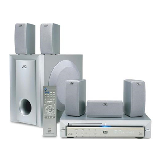
DVD DIGITAL CINEMA SYSTEM
STANDBY/ON
AUDIO
VCR
CONTROL
TV
VCR
OFF
ON
TV CHANNEL
TOP MENU
MENU
AUDIO/
FM MODE SUBTITLE
TV VOLUME
STEP
TV/VIDEO
DISPLAY
RETURN
SP-XSA5
TUNER PRESET
DOWN
UP
REW
FF
VCR CHANNEL
TUNING
B.SEARCH
F.SEARCH
ENTER
VOLUME
DVD
FM/AM
AUX
MUTING
STANDBY
STANDBY/ON
RM-STHA5R
DVD CINEMA SYSTEM
Contents
Safety precautions
Important for laser products
Preventing static electricity
Disassembly method
TH-A5R
SP-XCA5
COMPACT
DIGITAL VIDEO
AUDIO/FM MODE
DSP
VOLUME
SOURCE
DVD DIGITAL CINEMA SYSTEM TH-A5R
XV-THA5R
1-2
1-4
1-5
1-6
COPYRIGHT
2001 VICTOR COMPANY OF JAPAN, LTD.
SP-XSA5
D I G I T A L
S U R R O U N D
D I G I T A L
Wiring connection
Adjustment method
Description of major ICs
TH-A5R
Area suffix
B -------------------------- U.K.
E ------ Continental Europe
EN ------- Northern Europe
EV --------- Eastern Europe
EE ---- Russian Federation
SP-WA5
1-13
1-14
1-16~34
No.21046
Dec. 2001
Advertisement

Related Manuals for JVC TH-A5R

Summary of Contents for JVC TH-A5R
- Page 1 STANDBY AUDIO/FM MODE STANDBY/ON D I G I T A L VOLUME SOURCE S U R R O U N D DVD DIGITAL CINEMA SYSTEM TH-A5R D I G I T A L RM-STHA5R DVD CINEMA SYSTEM XV-THA5R SP-WA5 Contents...
- Page 2 TH-A5R 1. This design of this product contains special hardware and many circuits and components specially for safety purposes. For continued protection, no changes should be made to the original design unless authorized in writing by the manufacturer. Replacement parts must be identical to those used in the original circuits. Services should be performed by qualified personnel only.
- Page 3 TH-A5R (U.K only) 1. This design of this product contains special hardware and many circuits and components specially for safety purposes. For continued protection, no changes should be made to the original design unless authorized in writing by the manufacturer.
- Page 4 TH-A5R Important for laser products 5.CAUTION : If safety switches malfunction, the laser is able 1.CLASS 1 LASER PRODUCT to function. 2.DANGER : Invisible laser radiation when open and inter 6.CAUTION : Use of controls, adjustments or performance of lock failed or defeated. Avoid direct exposure to beam.
- Page 5 TH-A5R Preventing static electricity 1.Grounding to prevent damage by static electricity Electrostatic discharge (ESD), which occurs when static electricity stored in the body, fabric, etc. is discharged, can destroy the laser diode in the traverse unit (optical pickup). Take care to prevent this when performing repairs.
- Page 6 TH-A5R Top cover Disassembly method Removing the top cover (See Fig.1) Remove the four screws A attaching the top cover on the both sides of the body. Remove the two screws B on the back of the body. Fig.1 Remove the top cover from behind in the direction of the arrow while pulling both sides outward.
- Page 7 TH-A5R Removing the DVD mechanism assembly DVD mechanism assembly (See Fig.5 and 6) MPEG Prior to performing the following procedure, remove board the top cover. Disconnect the card wire from the connector J14 and J21 on the DVD MPEG board.
- Page 8 TH-A5R Removing the DSP board (See Fig.9) Harness band VW12 Main board DSP board Prior to performing the following procedure, remove the top cover, front panel assembly and jack board. Untied the harness band and disconnect the harness from the connector CW2 on the main board.
- Page 9 TH-A5R Removing the DVD power board Tie band (See Fig.12) Prior to performing the following procedure, remove the top cover, front panel assembly and DSP board. Disconnect the harness and card wire from the connector PW1, PW2 and PW5 on the DVD power board.
- Page 10 TH-A5R <DVD mechanism assembly section> DVD mechanism assembly (top side) Removing the DVD loader board (See Fig.1 to 3) Prior to performing the following procedure, remove the top cover and DVD mechanism assembly. Disconnect the card wire from the connector J6 on DVD MPEG board the DVD MPEG board.
- Page 11 TH-A5R DVD loading mechanism Removing the DVD traverse mechanism (top side) (See Fig.5) Prior to performing the following procedure, remove DVD traverse the top cover, DVD mechanism assembly, DVD mechanism loader board and DVD loading mechanism. Remove the four screws D attaching the DVD traverse mechanism to DVD loading mechanism.
- Page 12 TH-A5R <Speaker section> Net assembly [SP-XSA5 / Satellite speaker] It is exchange in a unit. [SP-XCA5 / Center speaker] It is exchange in a unit. Boss [SP-WA5 / Woofer] Removing the speaker unit (See Fig.1 to 3) Remove the four bosses and remove the net assembly.
- Page 13 TH-A5R Color codes are shown below. Wiring connection Brown Blue Violet Orange Gray Yellow White 3809-001273 Green Black 3809-001294 AH39-00104A AH39-00291A DSP1 BOARD DSP2 BOARD 1-13...
- Page 14 TH-A5R Adjustment method 1. Tuner *Adjustment Location of Tuner PCB AM(MW) OSC AM(MW) RF ITEAM Adjustment Adjustment 522~1629 KHz 603 KHz Received FREQ. Adjustment point Maximum Output 1~7.0V Output(Fig1-1) MAIN TESTER Fig 1-4 OSC Voltage Fig 1-4 OSC Voltage Fig 1-4 OSC Voltage...
- Page 15 TH-A5R FM THD Adjustment Output Output Output Output SSG FREQ. 98 MHz Antenna Terminal Adjustment Oscilloscope point FM S.S.G FM DETECTOR COIL Input (FD) Speaker 60 dB Terminal Output output output output output Input Input Input Input Minumum Distortion (0.4% below)
- Page 16 TH-A5R Description of major ICs ZiVA-5 (U8) : DVD controller 1. Pin layout VDD_3.3 DAI-DATA DAI-BCK/SYSCLKBP DAI-LRCK/IEC958BP MDATA31 MDATA30 C_CL MDATA29 C_DA MDATA28 RTS1 VDD_3.3 RXD1 MDQM3 TXD1 CTS1 MDATA27 MDATA26 VDD_3.3 MDATA25 SD-DATA7 MDATA24 SD-DATA6 MDATA23 SD-DATA5 MDATA22 SD-DATA4...
- Page 17 TH-A5R 2. Pin function (2/4) Name Pin No. Type Description Power 5-V supply voltage for 5V-tolerant I/O signals. VDDP 12, 20, 111, 152, 167, 181, 196 Power 3.3-V supply voltage for I/O signals VDD25 32, 44, 55, 63, 74, 87, 98, 104 Power 3.3-V supply voltage for SDRAM I/O signals...
- Page 18 TH-A5R 2. Pin function (3/4) Name Pin No. Type Description SDDATA[7]/VDATA2[7] Compressed data from DVD DSP. Bit 7. In parallel mode, bit 7 is the first /HDMARQ/GPIO24 (earliest in time) bit in the bitstream, while bit 0 is the last bit.
- Page 19 TH-A5R 2. Pin function (4/4) Name Pin No. Type Description IRRX1/GPIO0 IR Remote Receive. This input connects to an integrated (photo diode, band pass, demodulator) IR receiver. General Purpose I/O 0 IDC_CL/GPIO18 Serial clock signal for IDC data transfer. It should be pulled up to the positive supply voltage, depending on the device) using an external pull-up resistor.
- Page 20 TH-A5R CS493292 (DIC11) : Audio decoder 1. Pin layout 6 5 4 3 2 1 44 43 42 41 40 AUDATA2 A0,SCCLK DATA7,EMAD7,GPIO7 DATA6,ENAD6,GPIO6 RESET DATA5,EMAD5,GPIO5 AGND DATA4,EMAD4,GPIO4 FILT1 DGND2 FILT2 DATA3,EMAD3,GPIO3 CLKSEL DATA2,EMAD2,GPIO2 CLKIN DATA1,EMAD1,GPIO1 DATA0,EMAD0,GPIO0 CMPREQ,LRCLKN2 18 19 20 21 22 23 24 25 26 27 28 2.
- Page 21 TH-A5R 3. Pin function Function Pin No. Symbol 1,12,23 VD1,VD2,VD3 Digital Positive Supply 2,13,24 DGND1,DGND2,DGND3 Digital Supply Ground SPDIF Transmitter Output, Digital Audio Output 3 AUDATA3,XMT958 Host write strobe or Host data strobe or External Memory write enable or WR,DS,EMWR,GPIO10 General purpose input&...
- Page 22 TH-A5R SP3721A (U7) : DVD driver 1.Pin layout 64 ~ 49 ~ 32 2.Pin function (1/2) Symbol Function Pin No. RF Signal Inputs. Differential RF signal attenuator input pins. DVDRFP DVDRFN PD1,PD2 CD Photo detector Interface Inputs. Inputs from the CD photo detector error outputs.
- Page 23 TH-A5R 2.Pin function (2/2) Function Symbol Pin No. SIGO Bottom Envelope Output. Bottom envelope for Mirror detection. MEVO RF signal Input for Mirror. AC coupled inputs for the mirror detection circuit from the pull-in signal output. (PI) Pull-in Signal Output. The summing signal output of A,B,C,D or PD1, PD2 for mirror detection.
- Page 24 TH-A5R W986432DH (U5) : SDRAM 1. Pin layout 2. Block diagram CLOCK BUFFER CONTROL SIGNAL GENERATOR COMMAND DECODER COLUMN DECODER COLUMN DECODER CELL ARRAY CELL ARRAY BANK #0 BANK #1 MODE REGISTER SENSE AMPLIFIER SENSE AMPLIFIER ADDRESS BUFFER DATA CONTROL...
- Page 25 TH-A5R LC86P6548 (UIC1) : Microcontroller 1.Pin layout S19/PC3 S48/PG0 S18/PC2 S49/PG1 S17/PC1 S50/PG2 S51/PG3 S16/PC0 VDD3 S15/T15 S14/T14 S13/T13 S12/T12 VSS2 S11/T11 VDD2 S10/T10 S9/T9 S8/T8 S7/T7 P10/SO0 S6/T6 S5/T5 P11/SI0/SB0 S4/T4 P12/SCK0 S3/T3 P13/SO1 P14/SI1/SB1 S2/T2 S1/T1 P15/SCK1 2.Block diagram...
- Page 26 TH-A5R M11B416256A (U1) : DRAM 1. Pin layout 2. Pin function Pin No. Symbol Function 16~19,22~26 A0~A10 Address Input I/O0 I/O15 I/O1 I/O14 Row Address Strobe I/O2 I/O13 CASH Column Address Strobe/Upper Byte Control I/O3 I/O12 CASL Column Address Strobe/Lower Byte Control...
- Page 27 TH-A5R M6759 (U3) : MTP microcontroller 1. Pin layout 2. Pin function Pin No. Symbol Description Power supply for internal operation, 5V input Ground 36,37,38,39, P0.7-P0.0 8 bits bi-directional I/O port 40,41,42,43, AD7-0 Multiplexed address/data bus Reset signal XTAL1 Crystal In...
- Page 28 TH-A5R SST39VF800A (U6) : 8M Flash memory 1. Pin layout DQ15 DQ14 DQ13 DQ12 DQ11 DQ10 2. Block diagram EEPROM X-Decoder Cell Array Memory Address Address Buffer & Latches Y-Decoder Control Logic I/O Buffers & Data Latches DQ15-DQ0 3. Pin function...
- Page 29 TH-A5R LC75725E (UIC10) : VFD driver 1. Pin layout 48 47 46 45 44 43 42 41 40 39 38 37 36 35 34 33 OSCO OSCI 2. Block diagram 1 2 3 4 5 6 7 8 9 10 11 12 13 14 15 16...
- Page 30 TH-A5R 74VHCT244A (DIC12) : Buffer/Line driver 1. Pin layout 2. Pin function Symbol Function OE1,OE2 3-STATE Output Enable Inputs I0-I7 Inputs O0-O7 3-STATE Outputs 3. Truth table Inputs Outputs (Pins12,14,16,18) Inputs Outputs (Pins3,5,7,9) H:HIGH Voltage Level L:LOW Voltage Level I:Immaterial...
- Page 31 TH-A5R CS8415A (DIC14) : Digital audio receiver 1. Pin layout 2. Pin function Pin No. Symbol Function SDA/CDOUT SCL/CCLK SDA/CDOUT Serial Control Data I/O(I2C) / Data Out(SPI) AD0/CS AD1/CDIN EMPH RXP6 AD0/CS Address Bit 0(I2C) / Control Port Chip Select(SPI)
- Page 32 TH-A5R FAN8082 (U10) : DC motor driver 2. Block diagram 1.Pin layout DRIVER OUT PRE DRIVER BIAS LOGIC SWITCH 3. Pin function Pin No. Symbol Function Ground Output 1 Motor speed control Input 1 Input 2 Supply voltage (Signal) Supply voltage (Power)
- Page 33 TH-A5R CS4228A (DIC15) : D/A converter 1. Pin layout 2. Pin function Pin No. Symbol Function SDIN1 SDIN3 SDIN2 CENTER 1,2,3 SDIN2 Serial Audio Data In SDIN1 SDIN3 SDOUT Serial Audio Data Out SDOUT SCLK SCLK Serial Clock LRCK LRCK...
- Page 34 TH-A5R BA5983FM (U6) : 4CH driver 1.Block diagram STAND BY Level Shift Level Shift Level Shift Level Shift STAND BY CH1/2/3 2.Pin function Function Symbol Symbol Function Pin No. Pin No. Input for Bias-amplifier VO4(+) Non inverted output of CH4...
- Page 35 TH-A5R < M E M O > 1-35...
- Page 36 TH-A5R VICTOR COMPANY OF JAPAN, LIMITED AUDIO & COMMUNICATION BUSINESS DIVISION PERSONAL & MOBILE NETWORK BUSINESS UNIT. 10-1,1chome,Ohwatari-machi,Maebashi-city,371-8543,Japan 200112(V) (No.21046)
- Page 37 TH-A5R Block diagrams Main section V F D TUNER CL CE DI (MIC OPTION) LC75725E LC86P6548 3ohm POWER AUX L TUN L (60W) DVD L TDA7440 AUX R TUN R 6ohm DVD R CS49326 POWER (35W) 6ohm POWER (35W) DIGI IN...
- Page 38 TH-A5R TH-A5R DVD mecha block section RF AMP SP3721 RF AGC TRACKING RF&FOCUS &EQ ERROR ERROR MICOM 4M DRAM Parallel/serial DECK ASS’ Y M5701 CONTROL I/V AMP I/V AMP DVD Interface DVD ROM M6759 416C256 APC.LASER FOCUS OK CONTROLLER CONTROL&...
- Page 39 TH-A5R Standard schematic diagrams FL display & System control section / Power supply section Sheet 4/6 SHEET CIRCUIT DESCRIPTION NUMBER FL display & System control / Power supply Main Video signal output DVD loader DVD MPEG Parts are safety assurance parts.
- Page 40 TH-A5R TH-A5R Main section To Tuner Pack To DW14 Sheet 4/6 To DW10 Sheet 4/6 To PW5 Sheet 1/6 To DW13 Sheet 4/6 Tuner signal Front signal Center signal Rear signal SHEET 2/6...
- Page 41 TH-A5R Video signal output section JVR17 JVC10 M-DIN_4-P JVE18 JVC9 SWITCH_A/V_6P 330/16 SCRT1 AR_IN VIDEO_COMPO AR_OUT S_VIDEO_C AL_IN JVC11 AGND B_GND AL_OUT BLUE_IN AV_SW G_GND GREEN_IN To J21 FT_USE BA7612AF JVW3 JVR14 JVC6 JVC7 JVR19 R_GND Sheet 6/6 JVIC2 FGND...
- Page 42 TH-A5R TH-A5R DSP section Sheet 3/6 Sheet 1/6 Sheet 6/6 Sheet 2/6 FIC1 FIC12 Tuner signal Front signal Rear signal Digital audio signal Center signal SHEET 4/6...
- Page 43 TH-A5R DVD loader section RFVCC RFVCC RFGND RFVCC 2.2K 2.2K RFGND RD15 DQ15 2.2K RD14 MGND To PW4 DQ14 ROEJ RD13 DQ13 RHCASJ RD12 DQ12 RCASJ R132 8.2K RRASJ RD11 Sheet 1/6 DQ11 RWEJ RD10 PUHRF R124 680P DQ10 RFVCC RFGND CON_WAFER_4P_2.5m/m_S...
- Page 44 TH-A5R TH-A5R DVD MPEG section PLL_VDD IEC_958 FBSMT +5V_VID +5V_VID +5V_VID +5V_VID RXD_MDATA FBSMT REF_VDD FBSMT CON_WAFER_1m/m_SMD_ST 0.1u RRQ_MCE RRQ_MCE VR16 COMP PLL_GND DVDD SRQ_SCE FBSMT FBSMT COMP_OUT PLL_GND 47u/16 CLK_MCK VR17 S_VIDEO_C RXD_MDATA S_VIDEO_C S_VIDEO_Y COMP_OUT S_VIDEO_Y To VW2...
- Page 45 TH-A5R Printed circuit boards Front board Switch board Display board...
- Page 46 TH-A5R TH-A5R Main board (Forward side) 2-10...
- Page 47 TH-A5R Main board (Reverse side) 2-11...
- Page 48 TH-A5R TH-A5R DVD loader board (Forward side) DVD power board (Forward side) DVD MPEG board (Forward side) 2-12...
- Page 49 TH-A5R DVD power board (Reverse side) DVD loader board (Reverse side) DVD MPEG board (Reverse side) 2-13...
- Page 50 TH-A5R TH-A5R DSP1 board (Forward side) DSP1 board (Reverse side) DSP2 board (Forward side) DSP2 board (Reverse side) 2-14...
- Page 51 TH-A5R Jack board 2-15...
- Page 52 TH-A5R PARTS LIST [ TH-A5R ] * All printed circuit boards and its assemblies are not available as service parts. Area suffix B ------------------------------- U.K. E ----------- Continental Europe EN ------------ Northern Europe EV -------------- Eastern Europe EE ------------------------- Russia...
- Page 53 TH-A5R < M E M O >...
- Page 54 TH-A5R Exploded view of general assembly and parts list Block No. (XV-THA5) Jack board DSP board Main board DVD Boad (DVDpower) Front board...
- Page 55 TH-A5R TH-A5R Parts list (General assembly) XV-THA5 Parts list (General assembly) XV-THA5 Block No. M1MM Block No. M1MM Item Parts number Parts name Q'ty Description Area Item Parts number Parts name Q'ty Description Area 6002-000126 SCREW-TAPPING 2 FH 3*10 BLK...
- Page 56 TH-A5R Exploded view of general assembly and parts list Block No. (SP-WA5) Parts list (General assembly)SP-WA5 Block No. M2MM Item Parts number Parts name Q'ty Description Area AA000026-01 CABINET SPEAKER CR200027-01 LE10020-007A 70-059-416-02 SCREW 29-100-086-01 PACKING RING 53-000-158-11 ORNAMENT LV21155-002A...
- Page 57 TH-A5R DVD mechanism assembly and parts list Block No. DVD MPEG board DVD loader board...
- Page 58 TH-A5R Parts list (DVD mechanism) Block No. MJMM Item Parts number Parts name Q'ty Description Area BASE-MAIN 1 BLK AH61-00746A AH63-00294A TRAY-DISC 1 D/GRAY AH66-00159A LEVER-LIFT 1 BLK AH66-00160A PULLEY-MOTOR GEAR-PULLEY AH66-00161A AH66-00162A GEAR-MIDDLE AH66-00163A GEAR-TRAY CLAMPER-UPPER 1 UPPER AH66-00164A...
- Page 59 TH-A5R Electrical parts list (Main board) Block No. 01 Item Parts number Parts name Remarks Area Item Parts number Parts name Remarks Area 47KOHM,5%,1/16W 1.8NF,10%,50V AR48 2007-000097 CHIP RESISTOR C41FR 2203-001554 CHIP CAPACITOR KBP202G,200V 1.8NF,10%,50V 0402-001077 BRIDGE DIODE C41RL 2203-001554...
- Page 60 TH-A5R Electrical parts list (Main board) Block No. 01 Item Parts number Parts name Remarks Area Item Parts number Parts name Remarks Area 1SS355 1SS355 D217 0401-001090 DIODE 0401-001090 DIODE 1SS355 1SS355 D218 0401-001090 DIODE 0401-001090 DIODE 1SR154-400,400V 1SS355 0402-000309...
- Page 61 TH-A5R Electrical parts list (Main board) Block No. 01 Item Remarks Parts number Parts name Area Item Parts number Parts name Remarks Area 2401-000475 E.CAPACITOR 10UF,20%,50V 0501-000010 TRANSISTOR KSC1008,NPN 100UF,20%,16V KSA733,PNP 2401-001895 E.CAPACITOR Q20C 0501-000303 TRANSISTOR 1N4002,100V KSA733,PNP 0402-000127 DIODE...
- Page 62 TH-A5R Electrical parts list (Main board) Block No. 01 Item Remarks Parts number Parts name Area Item Parts number Parts name Remarks Area Q30FL 0502-001048 TRANSISTOR KSD1691,NPN R106 2007-000124 CHIP RESISTOR 2.2KOHM,5%,1/16 KSD1691,NPN 10KOHM,5%,1/16W Q30FR 0502-001048 TRANSISTOR R107 2007-000090 CHIP RESISTOR...
- Page 63 TH-A5R Block No. 01 Electrical parts list (Main board) Item Parts number Parts name Remarks Area Item Parts number Parts name Remarks Area 2.2KOHM,5%,1/16 10KOHM,5%,1/16W R32RL 2007-000124 CHIP RESISTOR 2007-000090 CHIP RESISTOR 2.2KOHM,5%,1/16 22KOHM,5%,1/16W R32RR 2007-000124 CHIP RESISTOR 2007-000094 CHIP RESISTOR...
- Page 64 TH-A5R Electrical parts list (Main board) Block No. 01 Item Remarks Item Remarks Parts number Parts name Area Parts number Parts name Area R82FL 2007-000082 CHIP RESISTOR 3.3KOHM,5%,1/16 R92RL 2007-000076 CHIP RESISTOR 330OHM,5%,1/16W 3.3KOHM,5%,1/16 330OHM,5%,1/16W R82FR 2007-000082 CHIP RESISTOR R92RR...
- Page 65 TH-A5R Block No. 01 Electrical parts list (Main board) Item Remarks Parts number Parts name Area ZD5C 0403-001079 ZENER DIODE UDZ3.9B,7%,200M ZD5FL 0403-001079 ZENER DIODE UDZ3.9B,7%,200M ZD5FR 0403-001079 ZENER DIODE UDZ3.9B,7%,200M ZD5RL 0403-001079 ZENER DIODE UDZ3.9B,7%,200M ZD5RR 0403-001079 ZENER DIODE UDZ3.9B,7%,200M...
- Page 66 TH-A5R Block No. 02 Electrical parts list (DSP board) Item Parts number Parts name Remarks Area Item Parts number Parts name Remarks Area 10UF,20%,16V 100UF,20%,10V CC11 2401-000407 E.CAPACITOR DC24 2401-000243 E.CAPACITOR 2.2UF,20%,50V 2.2UF,20%,50V CC12 2401-000650 E.CAPACITOR DC25 2401-000650 E.CAPACITOR CC13 2401-001238 E.CAPACITOR...
- Page 67 TH-A5R Electrical parts list (DSP board) Block No. 02 Item Remarks Item Remarks Parts number Parts name Area Parts number Parts name Area DR33 2007-000113 CHIP RESISTOR 33OHM,5%,1/16W FC45R 2203-001554 CHIP CAPACITOR 1.8NF,10%,50V 3.3KOHM,5%,1/16 0.33NF,5%,50V,N DR34 2007-000082 CHIP RESISTOR FC46L...
- Page 68 TH-A5R Electrical parts list (DSP board) Block No. 02 Item Remarks Item Remarks Parts number Parts name Area Parts number Parts name Area FR20L 2007-000086 CHIP RESISTOR 5.6KOHM,5%,1/16 RC36R 2203-000531 CHIP CAPACITOR 2.7NF,10%,50V 5.6KOHM,5%,1/16 2.7NF,10%,50V FR20R 2007-000086 CHIP RESISTOR RC39L...
- Page 69 TH-A5R Electrical parts list (DSP board) Block No. 02 Item Parts number Parts name Remarks Area Item Parts number Parts name Remarks Area 100OHM,5%,1/16W 0401-001090 DIODE 1SS355 UR67 2007-000074 CHIP RESISTOR HT-DL100, 100OHM,5%,1/16W UIC1 AH11-00049A MICOM UR68 2007-000074 CHIP RESISTOR...
- Page 70 TH-A5R Block No. 03 Electrical parts list (Front board) Item Parts number Parts name Remarks Area 16P,1.25MM,ST 3708-000451 CONNECTOR BOX,3P,2MM,AN 3711-000906 CONNECTOR 3404-001182 TACT SWITCH DC12V,50MA,100G DC12V,50MA,100G SW10 3404-001182 TACT SWITCH SW11 3404-001182 TACT SWITCH DC12V,50MA,100G 3404-001182 TACT SWITCH DC12V,50MA,100G...
- Page 71 TH-A5R Electrical parts list (Jack board) Block No. 04 Item Parts number Parts name Remarks Area 1UF,20%,50V JVC1 2401-001912 E.CAPACITOR 100NF,+80%20%,5 JVC10 2201-000783 C.CAPACITOR 100NF,+80%20%,5 JVC11 2201-000783 C.CAPACITOR 330UF,20%,16V JVC2 2401-001102 E.CAPACITOR 47UF,20%,16V JVC3 2401-001511 E.CAPACITOR 100NF,+80%20%,5 JVC4 2201-000783 C.CAPACITOR...
- Page 72 TH-A5R Block No. 05 Electrical parts list (DVD Loader board) Item Parts number Parts name Remarks Area Item Parts number Parts name Remarks Area 47UF,20%,16V 47NF,10%,16V,,1 2401-001975 E.CAPACITOR 2203-000972 CHIP CAPACITOR 47UF,20%,16V 100NF,10%,16C,1 CE10 2401-001975 E.CAPACITOR 2203-005005 CHIP CAPACITOR CE11 2401-001975 E.CAPACITOR...
- Page 73 TH-A5R Electrical parts list (DVD Loader board) Block No. 05 Item Remarks Item Remarks Parts number Parts name Area Parts number Parts name Area R118 2007-000084 CHIP RESISTOR 4.7KOHM,5%1608 2007-000113 CHIP RESISTOR 33OHM,5%,1608 4.7KOHM,5%1608 33OHM,5%,1608 R119 2007-000084 CHIP RESISTOR 2007-000113...
- Page 74 TH-A5R Electrical parts list (DVD Loader board) Block No. 05 Item Remarks Parts number Parts name Area 0903-001246 M6759,PLCC,44P XC61CN1902MR 1203-001369 033,T0-252,3P 1203-001293 BA5983FM,HSOP,2 1003-001305 SP3721A,TQFP,64 1201-001790 24P,1MM,ANGLE,S 3708-001574 CONNECTOR 13.5MHZ,15PPM 2801-003971 CRYSTAL 5.6V,5.4-5.8V 0403-000357 ZENER DIODE 3-23...
- Page 75 TH-A5R Electrical parts list (DVD MPEG board) Block No. 06 Item Parts number Parts name Remarks Area Item Parts number Parts name Remarks Area 100NF,10%,16C,1 120OHM,2.0X1.2 C100 2203-005005 CHIP CAPACITOR 3301-001495 BEAD 100NF,10%,16C,1 BLM21A121SP C101 2203-005005 CHIP CAPACITOR 3301-000353 BEAD...
- Page 76 TH-A5R Electrical parts list (DVD MPEG board) Block No. 06 Item Remarks Parts number Parts name Area 2007-000113 CHIP RESISTOR 33OHM,5%,1608 33OHM,5%,1608 2007-000113 CHIP RESISTOR 33OHM,5%,1608 2007-000113 CHIP RESISTOR 33OHM,5%,1608 2007-000113 CHIP RESISTOR 33OHM,5%,1608 2007-000113 CHIP RESISTOR 0OHM,5%,1608 2007-000070 CHIP RESISTOR...
- Page 77 TH-A5R < M E M O > 3-26...
- Page 78 TH-A5R Packing materials and accessories parts list Block No. EE only Block No. A9(Short) A10(Long) A1,A2,A4, A5,A6,A7 XV-THA5 SP-WA5 SP-XTHA5 3-27...
- Page 79 TH-A5R Packing materials and accessories parts list Block No. B E EN EV only A9(Short) Block No. A10(Long) A1,A2,A4, B only A5,A6,A7 A3:B only B only XV-THA5 SP-XTHA5 SP-WA5 3-28...
- Page 80 TH-A5R Parts list (Packing) Block No. M3MM Item Parts number Parts name Q'ty Description Area AH69-00532A CUSHION-SIDE,L AH69-00533A CUSHION-SIDE,R AH69-00581A CUSHION-PAD AH69-00552C PACKING-CASE E,EN,EV AH69-00552D PACKING-CASE AH69-00552A PACKING-CASE 1 DW-1 YEL PE BAG-SET AH69-10081H AH69-00525B PE BAG-I/B AH69-00665A PAD-ROLL AH69-00664C...