Table of Contents
Advertisement
Quick Links
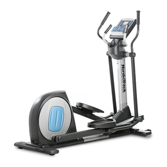
Model No. NTCCEL16909.0
Serial No.
Write the serial number in the
space above for reference.
Serial Number
QUESTIONS?
If you have questions, or if parts are
damaged or missing, PLEASE
CONTACT OUR CUSTOMER SER-
VICE DEPARTMENT DIRECTLY.
1-888-936-4266
CALL TOLL-FREE:
Mon.–Fri., 7:30 until 16:30 ET
(excluding holidays)
OR E-MAIL US:
customerservice@iconcanada.ca
CAUTION
Read all precautions and instruc-
tions in this manual before using
this equipment. Keep this manual
for future reference.
Decal
USERʼS MANUAL
www.nordictrack.com
Advertisement
Table of Contents

Related Manuals for NordicTrack NTCCEL16909.0


Summary of Contents for NordicTrack NTCCEL16909.0
- Page 1 USERʼS MANUAL Model No. NTCCEL16909.0 Serial No. Write the serial number in the space above for reference. Serial Number Decal QUESTIONS? If you have questions, or if parts are damaged or missing, PLEASE CONTACT OUR CUSTOMER SER- VICE DEPARTMENT DIRECTLY.
-
Page 2: Table Of Contents
Note: The decal(s) may not be shown at actual size. Keep hands and fingers clear of this area. A A TTENTION TTENTION Gardez vos mains et vos doigts ÈloignÈs de cet endroit. NordicTrack is a registered trademark of ICON IP, Inc. -
Page 3: Important Precautions
IMPORTANT PRECAUTIONS WARNING: To reduce the risk of serious injury, read all important precautions and instructions in this manual and all warnings on your elliptical exerciser before using your elliptical exerciser. ICON assumes no responsibility for personal injury or property damage sustained by or through the use of this product. -
Page 4: Before You Begin
BEFORE YOU BEGIN Thank you for selecting the revolutionary NordicTrack tions after reading this manual, please see the front COMMERCIAL™ XM elliptical exerciser. The cover of this manual. To help us assist you, note the NordicTrack COMMERCIAL XM elliptical exerciser... -
Page 5: Assembly
ASSEMBLY Assembly requires two persons. Place all parts of the elliptical exerciser in a cleared area and remove the packing materials. Do not dispose of the packing materials until assembly is completed. In addition to the included tools, assembly requires a Phillips screwdriver and an adjustable wrench As you assemble the elliptical exerciser, use the drawings below to identify small parts. - Page 6 To make assembly easier, read the information on page 5 before you begin. Remove the two packing inserts from the pack- ing materials. With the help of another person, place the packing inserts under the front of the Frame (1) as shown. Have the other person hold the elliptical exerciser to prevent it from tipping until this step is completed.
- Page 7 3. Tip: Do not pinch the Wire Harnesses (97, 54) during this step. Start all screws before tightening any of them. While another person holds the Upright (6) near the Frame (1), connect the Upper Wire Harness (97) to the Lower Wire Harness (54). Attach the Upright (6) to the Frame (1) with five 5/16"...
- Page 8 5. Identify the Right Pedal Plate (107), which is attached to the Right Pedal (62). The Right Pedal is marked with a “Right” sticker. Attach the Right Pedal Plate (107) to the Right Pedal Arm (8) with three 3/8" x 2 1/2" Patch Screws (88).
- Page 9 7. While a second person holds the Console (60) near the Upright (6), connect the console wire to the Upper Wire Harness (97). Then, connect the console pulse wire to the Hand Pulse Wire (65). Insert the excess wire downward into the Console Wire Upright.
- Page 10 9. IMPORTANT: If the elliptical exerciser has been exposed to cold temperatures, allow it to warm to room temperature before plug- ging in the Power Cord (55). If you do not do this, you may damage the console displays or other electronic components. Plug the Power Cord (55) into the power socket at the rear of the elliptical exerciser.
-
Page 11: How To Use The Elliptical Exerciser
HOW TO USE THE ELLIPTICAL EXERCISER HOW TO PLUG IN THE POWER CORD HOW TO MOVE THE ELLIPTICAL EXERCISER This product must be grounded. If it should mal- Due to the size and weight of the elliptical exer- ciser, moving it requires two persons. Stand in function or break down, grounding provides a path of least resistance for electric current to reduce the risk front of the elliptical exerciser, hold the upright, and... - Page 12 HOW TO EXERCISE ON THE ELLIPTICAL EXERCISER To mount the elliptical exerciser, hold the handlebars and step onto the pedal that is in the lowest position. Next, step onto the other pedal. Push the pedals until they begin to move with a continuous motion. Handlebars Note: The crank arms can turn in either direction.
- Page 13 CONSOLE DIAGRAM FEATURES OF THE CONSOLE The console also offers sixteen intensity control work- outs. Each intensity control workout automatically The advanced console offers an array of features changes the resistance of the pedals and prompts you designed to make your workouts more effective and to increase or decrease your pedaling pace as it enjoyable.
- Page 14 HOW TO USE THE MANUAL MODE 4. Follow your progress with the display. The far left section of Note: If there is a sheet of clear plastic on the face of the display—This section the console, remove the plastic. of the display will show 1.
- Page 15 5. Measure your heart rate if desired. 6. Turn on the fan if desired. If there are The fan has high and low speed settings. Press sheets of clear the Fan button repeatedly to select a fan speed or Contacts plastic on the to turn off the fan.
- Page 16 HOW TO USE A TARGET TONING WORKOUT As you exercise, the console will display a variety of exercise instructions. For example, the console 1. Press any button on the console or begin ped- may instruct you to pedal backwards or to use aling to turn on the console.
- Page 17 If the resistance level or the ramp incline level for the workout is completed, the display will continue the current segment is too high or too low, you can to show exercise feedback; however, the display manually override the setting by pressing the will not show the elapsed time until you select the Resistance or the Ramp buttons.
- Page 18 HOW TO USE AN INTENSITY CONTROL To increase or decrease the overall intensity of the WORKOUT workout, press the + and - buttons next to the matrix. The resistance levels of all remaining seg- 1. Press any button on the console or begin ped- ments in the workout will then increase or aling to turn on the console.
- Page 19 HOW TO CREATE A CUSTOM WORKOUT 3. Begin pedaling to start the workout, and program the desired settings. 1. Press any button on the console or begin ped- aling to turn on the console. Each custom workout is divided into 40 one- minute segments.
- Page 20 HOW TO USE A CUSTOM WORKOUT As you exercise, you will be prompted to keep your pedaling pace near the target pace setting for 1. Press any button on the console or begin ped- the current segment. When the words PEDAL aling to turn on the console.
-
Page 21: Maintenance And Troubleshooting
MAINTENANCE AND TROUBLESHOOTING HOW TO ADJUST THE BELT Inspect and tighten all parts of the elliptical exerciser regularly. Replace any worn parts immediately. If the pedals slip while you are pedaling, even while To clean the elliptical exerciser, use a damp cloth and the resistance is adjusted to the highest setting, the a small amount of mild soap. -
Page 22: Exercise Guidelines
EXERCISE GUIDELINES WARNING: Burning Fat—To burn fat effectively, you must exer- cise at a low intensity level for a sustained period of Before beginning time. During the first few minutes of exercise, your this or any exercise program, consult your body uses carbohydrate calories for energy. - Page 23 SUGGESTED STRETCHES The correct form for several basic stretches is shown at the right. Move slowly as you stretch—never bounce. 1. Toe Touch Stretch Stand with your knees bent slightly and slowly bend forward from your hips. Allow your back and shoulders to relax as you reach down toward your toes as far as possible.
-
Page 24: Part List
PART LIST—Model No. NTCCEL16909.0 R0909A Key No. Qty. Description Key No. Qty. Description Frame Wheel Front Stabilizer Left Pivot Cover Rear Stabilizer Right Pivot Cover Ramp Lower Wire Harness Right Ramp Cover Power Cord Upright Left Pedal Assembly Left Handlebar... - Page 25 Key No. Qty. Description Key No. Qty. Description M12 Fender Washer – 10" Ground Wire 5/8" Wave Washer – 12" White Jumper Wire F/F 3/4" Wave Washer – 12" Black Jumper Wire F/F 5/16" Washer – 60" Wire Harness 5/16" Split Washer –...
-
Page 26: Exploded Drawing
EXPLODED DRAWING A—Model No. NTCCEL16909.0 R0909A... - Page 27 EXPLODED DRAWING B—Model No. NTCCEL16909.0 R0909A...
-
Page 28: Ordering Replacement Parts
ORDERING REPLACEMENT PARTS To order replacement parts, see the front cover of this manual. To help us assist you, please be prepared to provide the following information when contacting us: • the model number and serial number of the product (see the front cover of this manual) •...