Sullair Supervisor Controller User Manual
Hide thumbs
Also See for Supervisor Controller:
- Instruction manual (37 pages) ,
- Operator's manual (36 pages)
Table of Contents
Advertisement
USER MANUAL
S
C
™
UPERVISOR
ONTROLLER
PART NUMBER:
02250146-049 R02
KEEP FOR
FUTURE
WARRANTY NOTICE
REFERENCE
SULLAIR CORPORATION
©
Failure to follow the instructions
The information in this manual is current
and procedures in this manual or,
as of its publication date, and applies to
misuse of this equipment will
compressor serial number:
VOID its warranty!
200906010000
and all subsequent serial numbers.
Advertisement
Table of Contents

Related Manuals for Sullair Supervisor Controller


Summary of Contents for Sullair Supervisor Controller
- Page 1 PART NUMBER: 02250146-049 R02 KEEP FOR FUTURE WARRANTY NOTICE REFERENCE SULLAIR CORPORATION © Failure to follow the instructions The information in this manual is current and procedures in this manual or, as of its publication date, and applies to misuse of this equipment will...
- Page 2 AIR CARE SEMINAR TRAINING Sullair Air Care Seminars are courses that provide hands-on instruction for the proper operation, maintenance, and servicing of Sullair products. Individual seminars on Stationary compressors and compressor electrical systems are offered at regular intervals throughout the year at Sullair’s corporate headquarters training facility located at Michigan City, Indiana.
-
Page 3: Table Of Contents
TABLE OF CONTENTS SECTION 1—SAFETY GENERAL PERSONAL PROTECTIVE EQUIPMENT ELECTRICAL SHOCK DECALS SECTION 2—DESCRIPTION SUPERVISOR KEYBOARD LAYOUT MAIN DISPLAY FUNCTION MENU STATUS—CURRENT PRESSURES, TEMPERATURES, INPUTS AND OUTPUTS CONTROL PARAMETERS—PRESSURE, TEMPERATURE AND TIMER SETTINGS MAINTENANCE—PREVENTIVE MAINTENANCE INFORMATION AND TIMERS FAULT LOG—LOG OF PREVIOUS FAULTS SENSOR LOG SEQUENCING—SEQUENCING &... - Page 4 TABLE OF CONTENTS MACHINE BEHAVIOR AFTER A POWER OUTAGE REMOTE STOP/START INPUT BROWN OUT INPUT SECTION 5—WIRING DIAGRAMS SECTION 6—VARIABLE SPEED DRIVE SAFETY OVERVIEW INSTALLATION SUPERVISOR DISPLAY AND MENUS STARTUP OF NEW COMPRESSOR PACKAGE FAULT AND WARNING CODES COMMISSIONING YOUR VSD: AFTER THE FIRST 48 HRS OF OPERATION: EVERY SIX MONTHS 6.10...
-
Page 5: Section 1-Safety
GENERAL tions relative to personal protective equipment, such as eye and face protective equipment, Sullair Corporation and its subsidiaries design and respiratory protective equipment, equipment manufacture all of their products so they can be intended to protect the extremities, protective operated safely. - Page 6 If a decal becomes source so others will not inadvertently restore damaged, contact your nearest Sullair Department power. for replacement parts (Note: When ordering new E. Disconnect, lock out, and tag all power at source decals, use part number printed on decal face).
- Page 7 SECTION 1 Figure 1-1: Decals PART NO. DESCRIPTION NOTE 250017-903 decal, warning auto start 250027-935 decal, danger breath air 250003-144 sign, warning “food grade” lube 041065 decal, auto start (I) OSHA and FDA guidelines are superseded by any Federal, State or Local regulations whenever applicable.
- Page 8 NOTES...
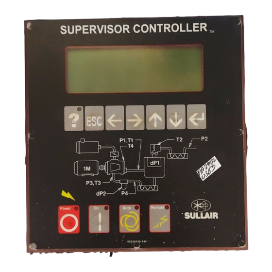
- Page 9 SUPERVISOR CONTROLLER™ USER MANUAL Section 2 DESCRIPTION Figure 2-1: Supervisor Controller Panel SUPERVISOR KEYBOARD LAYOUT —Used to edit text or numbers (move cursor left). Refer to Figure 2-1. The Display module has eleven keys grouped in two rows. —Used to edit text or numbers (move cursor The top row has the following seven keys : right).
-
Page 10: Function Menu
System Display—Display of modes of machines in a sequencing system. Line 1—Machine state : Calibration—Correction factors for pressures. E-Stop—E-Stop button pressed, or auxiliary E-Stop Test—Used by Sullair personnel for troubleshooting present. serial communications. Stopped—Machine not running. Factory Setup—Model settings. Unloaded—Machine running unloaded. -
Page 11: Status-Current Pressures, Temperatures, Inputs And Outputs
Drain Time is the length of the time Load Cycles—Number of load/unload cycles. energized. This does not apply to the Sullair SCD zero loss drain, which is not controlled or monitored Starts—Number of times machine has started. -
Page 12: Maintenance-Preventive Maintenance Information And Timers
SUPERVISOR CONTROLLER™ USER MANUAL SECTION 2 Restart Time is set to 10 seconds, then the machine Prim.—Primary air filter part number. will be enabled to start after 10 seconds. Sec.—Secondary air filter part number. Wye to delta transition timer—Also used to control Oil hours—Hours before oil change. -
Page 13: System Display-Display Of Modes Of Machines In A Se
SECTION 2 SUPERVISOR CONTROLLER™ USER MANUAL 2.10 SYSTEM DISPLAY—DISPLAY that the machine is running increments this counter. OF MODES OF MACHINES IN When then ‘Sequence By’ parameter is set to A SEQUENCING SYSTEM ‘Hours’, the machine with the least amount of Seq Hrs is started first, and the machine with the most Seq Hrs is shut off first. -
Page 14: 2.12 Test
VSD- Describes signal from Supervisor controls to SETTINGS. the VSD controls: None—No VSD The factory setup display is used by Sullair personnel to initially set up the machine. The following values Pressure—The Supervisor pressure signal is reflect the machine configuration. - Page 15 NOTES...
- Page 16 Table 2-1: Supervisor Controller Menu Tree...
-
Page 17: Motor Rotation Direction Check
SUPERVISOR CONTROLLER™ USER MANUAL Section 3 START-UP PROCEDURES MOTOR ROTATION 4. Start the compressor in the desired operating DIRECTION CHECK mode After the electrical wiring has been done, it is 5. Slowly open the shut-off valve to the service necessary to check the direction of the motor line. - Page 18 NOTES...
-
Page 19: Troubleshooting Introduction
It recommended check, consult your nearest Sullair contains symptoms and usual causes for the Distributor or the Sullair Corporation factory Service described problems. However, DO NOT assume that Department. these are the only problems that may occur. All Table 4-1: Troubleshooting Guide—Supervisor Controller... - Page 20 SUPERVISOR CONTROLLER™ USER MANUAL SECTION 4 Table 4-1: Troubleshooting Guide—Supervisor Controller Message Model Enable Probable Cause Remedy E-Stop ALWAYS Auxiliary E-Stop String Check auxiliary E-Stop Open devices. E-Stop String Check wiring. Low Water Pressure Water- Cooling Water Pressure Check for closed valves or cooled Below 10 psi (0.7bar)
- Page 21 SECTION 4 SUPERVISOR CONTROLLER™ USER MANUAL Table 4-1: Troubleshooting Guide—Supervisor Controller Message Model Enable Probable Cause Remedy P3 Oil Pressure Low, dP3 Oil ALWAYS Oil Pressure Low Oil pump failure, consult Sul- Pressure Low lair service department. Oil filter clogged; replace oil filter.
- Page 22 SUPERVISOR CONTROLLER™ USER MANUAL SECTION 4 Table 4-1: Troubleshooting Guide—Supervisor Controller Message Model Enable Probable Cause Remedy P1 Sump Pressure Low FLOODED ALWAYS Sump Pressure Low Check pressure sensor, wir- ing and tubing. Machine may have failed to start. T1 Interstage HIgh, T2 Dis- ALWAYS High Temp.
- Page 23 SECTION 4 SUPERVISOR CONTROLLER™ USER MANUAL Table 4-1: Troubleshooting Guide—Supervisor Controller Message Model Enable Probable Cause Remedy VSD Com Fault Communication Error Check for intermittent con- Detected trol wiring by Drive to drive. VSD Param Lim Fault Communication Error at Check control wiring to drive.
- Page 24 SUPERVISOR CONTROLLER™ USER MANUAL SECTION 4 Table 4-2: Analog Alarms (Flooded Screw Compressors Less Than 200 psi) Sensor Type Limit Start Delay Run Delay Check (*) Comment HIgh Inhibit At Start High sump psi at start Low Fault When Running...
- Page 25 SECTION 4 SUPERVISOR CONTROLLER™ USER MANUAL Table 4-3: Analog Alarms (LS-16T, LS-20T and LS-20TS Compressors) Sensor Type Limit Start Delay Run Delay Check (*) Comment HIgh Inhibit At Start High sump psi at start Low Fault When Running Immediate Fault...
- Page 26 SUPERVISOR CONTROLLER™ USER MANUAL SECTION 4 Table 4-4: Parameters Type Enable Default Display Text Comment Setup Always Press Tran 200,250,500, 750 Setup X200 P1 Max 250psi transducer Setup X250 P1 Max 200psi transducer Setup X500 P1 Max 500psi transducer Setup...
- Page 27 SECTION 4 SUPERVISOR CONTROLLER™ USER MANUAL Table 4-4: Parameters Type Enable Default Display Text Comment User X500 Unload 500psi transducer unload pressure User Always Unload 750psi transducer unload pressure User Always Load Delta Differential pressure from unload pressure User Always...
- Page 28 SUPERVISOR CONTROLLER™ USER MANUAL SECTION 4 MACHINE BEHAVIOR AFTER REMOTE STOP/START A POWER OUTAGE INPUT Condition: Machine was in a running or ready Table 4-6 describes how a machine reacts to the condition when power was lost. Table 4-5 describes Remote Start/Stop input.
- Page 29 SECTION 4 SUPERVISOR CONTROLLER™ USER MANUAL Table 4-5: Machine Power Outage Behavior Remote Local/ Seq. Mode Start/ Run Mode Action (State) Remote Stop Disabled xxxx xxxx Cont Manual Stop Disabled xxxx xxxx Auto Start after Restart delay & P2 < Load psi, & P1 < 5 psig...
- Page 30 NOTES...
-
Page 31: Section 5-Wiring Diagrams
SUPERVISOR CONTROLLER™ USER MANUAL Section 5 WIRING DIAGRAMS... - Page 32 Figure 5-1: WIRING DIAGRAM—SUPERVISOR COMMUNICATION MODULE 02250131-248 R05...
- Page 33 Figure 5-2: WIRING DIAGRAM—SUPERVISOR CONTROL Prior to April, 2009 NOTES DASHED LINES INDICATE TYPICAL FIELD CONNECTIONS THAT VARY DEPENDING ON COMPRESSOR BEING RETROFITTED AND IS FIELD WIRED. FACTORY WIRING IS SOLID. DISPLAY E-STOP CONNECTION IS WIRED TO TERMINAL BLOCK INSIDE REAR COVER OF DISPLAY. CHASSIS GROUND WIRE TO BE AS SHORT AS POSSIBLE 02250132-198 R04...
- Page 34 Figure 5-3: WIRING DIAGRAM—SUPERVISOR CONTROL After April, 2009 NOTES DASHED LINES INDICATE TYPICAL FIELD CONNECTIONS THAT VARY DEPENDING ON COMPRESSOR BEING RETROFITTED AND IS FIELD WIRED. FACTORY WIRING IS SOLID. DISPLAY E-STOP CONNECTION IS WIRED TO TERMINAL BLOCK INSIDE REAR COVER OF DISPLAY. CHASSIS GROUND WIRE TO BE AS SHORT AS POSSIBLE BELDEN TYPE 9842 4 COND.
-
Page 35: Section 6-Variable Speed Drive
SUPERVISOR CONTROLLER™ USER MANUAL Section 6 VARIABLE SPEED DRIVE SAFETY WARNING The following special instructions apply to VSD packages provided with electronic adjustable speed Refer all drive service to trained techni- motor drives. These are in addition to other warnings cians. -
Page 36: Overview
OVERVIEW (U, V, W) to avoid damaging the variable speed drive during motor or cable testing. The Sullair VSD drive application is custom designed for operation of air compressors. All necessary control functions performed... - Page 37 SECTION 6 SUPERVISOR CONTROLLER™ USER MANUAL Table 6-1: Conductor and Fuse Sizes (380/460V) Wire Size Power Wire Size Power Wire Size Size (A) Fuse (A) Wire Size Ground C Rated C Rated Ground Wire) Wire) 2x4/0 2x2/0 2x250 2x3/0 2x250...
-
Page 38: Installation
SUPERVISOR CONTROLLER™ USER MANUAL SECTION 6 INSTALLATION Power %—Average percent of power at full capacity. KCF—Running total of air delivered in thousands of This variable speed AC drive has been properly cubic feet. mounted, adjusted, and tested prior to shipment of the compressor package. -
Page 39: Startup Of New Compressor Package
SECTION 6 SUPERVISOR CONTROLLER™ USER MANUAL Status displays. For example, enter 0.070 for 7 cents operating conditions and user adjustments. per KWH. Nominal HP—The nameplate horsepower of the Saving vs—The basis for savings estimates. The main drive motor. cost of VSD operation can be compared to Inlet Nominal Volts—The compressor package rated... -
Page 40: Fault And Warning Codes
SUPERVISOR CONTROLLER™ USER MANUAL SECTION 6 FAULT AND WARNING Supervisor constantly monitors drive CODES performance through the serial channel. The following messages are specifically displayed by the Supervisor in the event of problems. Fault Possible Cause Solution VSD Param Lim Fault... - Page 41 SECTION 6 SUPERVISOR CONTROLLER™ USER MANUAL Code Fault Possible Cause Solution Emergency stop An Emergency stop signal was Determine the reason for the Emer- received from one of the digital gency stop and remedy it. inputs Saturation trip • defective component Cannot be reset from the keypad.
- Page 42 Values displayed on the counters are incorrect Microprocessor • faulty operation Reset the fault and restart. Should watchdog fault • component failure the fault reoccur, contact Sullair service. Startup prevented Startup of the drive has been pre- Check Start Enable/Interlock set- vented. tings.
-
Page 43: Commissioning Your Vsd
Supervisor Controller VSD Status/ Drive Temp. COMMISSIONING YOUR VSD: • Following all proper safety precautions, check or • Record all Supervisor Controller / VSD Set Up perform the following: parameters for later reference. 1. Using clean dry compressed air to clean the •... -
Page 44: 6.11 Cleaning Vsd Heat Sinks
Sullair Technical 3. Using clean dry air only blow out this area. Be Assistance at: 1-800 Sullair. sure to not allow any debris to enter the VSD. 4. Reinstall the rear VSD cover and screws. 6.11 CLEANING VSD HEAT SINKS 5. - Page 45 SECTION 6 SUPERVISOR CONTROLLER™ USER MANUAL AN REMOVAL AND REPLACEMENT 50-60 /480 20-40 /480 LEANING 1. If necessary remove VFD from machine. 1. Remove front cover of VSD. 2. Remove the screws that hold the back cover on. This will give you the area that the heat 2.
- Page 46 SUPERVISOR CONTROLLER™ USER MANUAL SECTION 6 50-60 /480 removal. Caution the fan cable is still con- LEANING nected. (Be sure to not allow any debris to 1. Remove VSD from machine. enter VSD.) 2. Remove fan. This will give you the area that 6.
- Page 47 SECTION 6 SUPERVISOR CONTROLLER™ USER MANUAL AN REMOVAL AND REPLACEMENT – 200 /480 RAME 1. Remove top plate (1) and the control box mounting plate (2)front (1,3) of VSD box. See pictures at right. 2. Remove the front covers (1,3) and side cov- ers (2).
-
Page 48: Cleaning Vsd Heat Sink Filters
SUPERVISOR CONTROLLER™ USER MANUAL SECTION 6 6.12 CLEANING VSD HEAT SINK 2. Remove the filter from the assembly. FILTERS (The filters are magnetic and should pull off easily.) If the machine is equipped with a VSD filter, it will 3. With a water hose, spray the filter from the require maintenance as needed in order to keep the magnet side. - Page 49 SECTION 6 SUPERVISOR CONTROLLER™ USER MANUAL FILTER ELEMENT VSD FILTER DRAWING V200TS Figure 6-2: V200TS...
- Page 50 SUPERVISOR CONTROLLER™ USER MANUAL SECTION 6 VSD FILTER DRAWING V INSTALL THE FILTER ELEMENT ON THE UNDERSIDE OF THE MOUNTING PLATFORM ON THE FRAME. THE FILTER IS TO COVER THE AIR OPENING TO THE VSD. Figure 6-3: V200TS...
- Page 51 NOTES...
- Page 52 Always air. Always there. WWW.SULLAIR.COM SULLAIR CORPORATION 3700 East Michigan Boulevard • Michigan City, Indiana, 46360 U.S.A. Telephone: 1-219-879-5451 Printed in the U.S.A. Specifications subject to change without prior notice. E12EP...