Table of Contents

Related Manuals for Sullair Supervisor


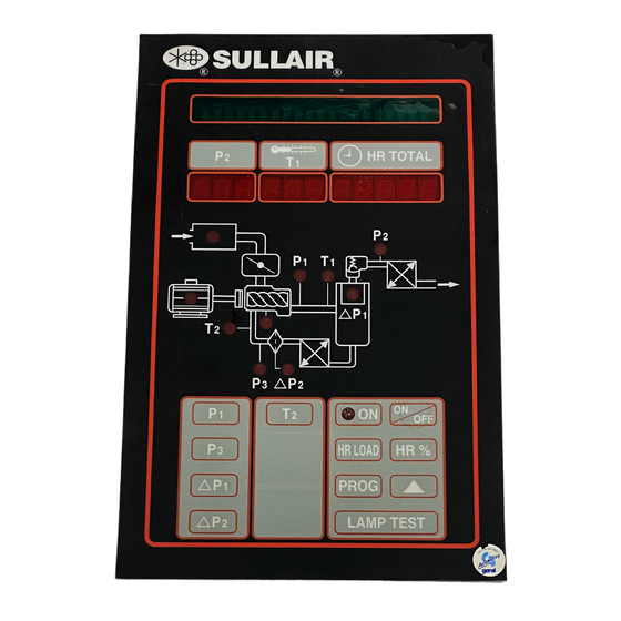
Summary of Contents for Sullair Supervisor
- Page 1 S S U U P P E E R R V V I I S S O O R R C C O O N N T T R R O O L L L L E E R R ™ ™ SEQUENCING & PROTOCOL MANUAL (Including Supervisor II Controller) OPERATOR’S MANUAL KEEP FOR...
- Page 2 AIR CARE SEMINAR TRAINING Sullair Air Care Seminars are courses that provide hands-on instruction in the proper operation, mainte- nance and service of Sullair equipment. Individual seminars on Industrial compressors and compressor electrical systems are presented at regular intervals throughout the year at a dedicated training facility at Sullair’s corporate headquarters in Michigan City, Indiana.
-
Page 3: Table Of Contents
2.6 SYSTEM SETUP AND TUNING 2.7 CHANGING SEQUENCE PARAMETERS 2.7.1 FOR SUPERVISOR 2.7.2 FOR SUPERVISOR II DELUXE 2.8 SYSTEM DISPLAY- SUPERVISOR 2.9 SYSTEM DISPLAY- SUPERVISOR II DELUXE 2.10 REMOVING A MACHINE FROM SEQUENCE FOR MAINTENANCE 2.11 CALIBRATION OF P2 PRESSURE TRANSDUCERS- SUPERVISOR 2.12 CALIBRATION OF P2 PRESSURE... - Page 4 OPERATION WITH REMOTE CONTROLLERS 4.1 NORMAL OPERATION 4.2 CONTROLS WIRING AND ADJUSTMENT- SUPERVISOR 4.3 CONTROLS WIRING AND ADJUSTMENT- SUPERVISOR II DELUXE Section 5 SEQUENCING TIMERS 5.1 RECOVERY TIME & DELAYED START TIMER 5.1.1 Example 1: Unload Operation 5.1.2 Example 2: Load Operation 5.1.3 Example 3: Starting Example...
- Page 5 TABLE OF CONTENTS Section 6 PAGE SUPERVISOR PROTOCOL (CONTINUED) 6.5 MESSAGE FORMAT 6.6 MESSAGE TYPES 6.7 DATA TYPES BACK COVER ADDRESSES AND TELEPHONE NUMBERS...
-
Page 7: Safety
Supervisor and Supervisor II Deluxe controllers all feature internal sequencing functions. Supervisor requires a communications module for these features. These operate as a dis- tributed control system (rather than a master-slave relationship), so the system remains operational even if a member is taken off-line. Refer to Section 2 for details. - Page 8 Section 1 SAFETY AND INTRODUCTION Section 4 covers application of controllers in master-controlled systems. Timers used in internal sequencing are described in Section 5. Section 6 contains technical details of the hardware and protocol used on the communica- tion bus. Other equipment may monitor this for data and presentation of system perform- ance.
-
Page 9: Normal Operation
Section 2 SEQUENCING WITH MULTIPLE SUPERVISOR CONTROLS 2.1 NORMAL OPERATION Supervisor and Supervisor II Deluxe controllers all feature internal sequencing functions. To enable any Supervisor in the system, press the Auto key and Remote key on the key- pad. Enable the Supervisor II Deluxe by simply pressing the Auto button. -
Page 10: Controls Wiring
HOURS mode. 5. Set the machines to run in AUTO mode. On the Supervisor, also press the Remote key to arm the machines for sequencing. Machines will start immediately if the P2 system pressure is low. -
Page 11: System Setup And Tuning
Section 2 SEQUENCING WITH MULTIPLE SUPERVISOR CONTROLS 120 seconds, if the pressure continues to drop the timer will count down faster. When the timer expires or the pressure drops below 90 psig (6.2 bar) the first machine is started. If the pressure does not go above 90 psig (6.2 bar) for 10 seconds (Recovery Time) the next... -
Page 12: Changing Sequence Parameters
Lowest Pressure set point, and after the recov- ery timer expires. 2.7 CHANGING SEQUENCE PARAMETERS 2.7.1 FOR SUPERVISOR CONTROLLER: To change parameters on the Supervisor Controller, push the Down arrow key until Sequencing menu is displayed. Press Enter . To select a parameter for change, move up... -
Page 13: For Supervisor
Sequence by (SEQUENCE [9]) – Select the desired sequencing mode Seq Hrs - To change this parameter in the Supervisor, push the key and change the values as described above. The maximum value for sequence hours is 100,000. A rollover to zero will occur if that number is exceeded. -
Page 14: System Display- Supervisor
This time is displayed while in sequence mode of operation. (BAUD RATE [8]) – Supervisor II Deluxe has adjustment of the serial communications baud rate, almost always set to 9600. The Supervisor is fixed at 9600 baud. All controllers in the system must be the same speed. -
Page 15: Removing A Machine From Sequence For Maintenance
This re-calibration is best done when the system is at a stable pressure. Measure the pressure using an independent gauge then change the calibration parameter for P2 so that the Supervisor reads the same as the gauge. Changing of the calibration parameters is... -
Page 16: Calibration Of P2 Pressure Transducers- Supervisor Ii Deluxe
P2 so that the supervisor reads the same as the gauge. The changing of the calibration parameters is entered by a special key sequence to protect from inadvertent change. The key sequence... -
Page 17: Variable Speed Drive Applications
The fixed-speed machine(s) must be set up for load/unload operation. If controlled with Supervisor II Deluxe controllers, the pressure regulator/s must be made to have no effect by operating the system below their effective range. If controlled by the Supervisor Controller, the controls may be programmed for Load/No load operation whereby the Full Load valve is energized any time the machine is running, thus defeating modulation. -
Page 18: Setup For Multiple Vsd Compressors
Section 3 SEQUENCING WITH VARIABLE SPEED DRIVE COMPRESSORS at 101 psi. The system will normally cruise at 98-100 psi. 3.3 SETUP FOR MULTIPLE VSD COMPRESSORS With pressure-controlled VSD circuits, configure all compressors by Sequence Hours or Com Number, as desired. Enable the Max. Speed Input function. All but one of the com- pressors will be full-loaded, thus limiting the pressure to the rated value of the machines. -
Page 19: Normal Operation
Local/Master Output K8 D5, D6 and D7 are wired through customer furnished relay contacts to ground (Supervisor Signal GND). If D5 is open the machine will stop, and be held stopped. If D5 is grounded, the machine will be enabled to start; the following table describes how the other inputs work:... -
Page 20: Controls Wiring And Adjustment- Supervisor Ii Deluxe
Inputs D8, D9 and D10 are wired through customer furnished relay contacts to ground (Supervisor II Deluxe Common J3-20). If D10 is open the machine will stop, and be held stopped. If D10 is grounded the machine will be enabled to start. If remote start/stop is not needed then jumper D10 (J3-19) to GND (J3-20). -
Page 21: Recovery Time & Delayed Start Timer
Section 5 SEQUENCING TIMERS 5.1 RECOVERY TIME AND DELAYED START TIMER The Recovery Timer is used to keep machines from starting, loading or unloading all at the same time. The Delayed Start timer is used to keep machines from starting unnecessarily due to temporary load changes. -
Page 22: Example 1: Unload Operation
Section 5 SEQUENCING TIMERS 5.1.1 EXAMPLE 1– UNLOAD OPERATION Suppose there are three machines running and loaded, the recovery timer is set to 10 sec- onds and the unload pressure is set at 110 on all three machines. The sequence unload pressure will be 108 Machine Status... -
Page 23: Example 3: Starting Example (Pressure Drops Below Lowest Pressure Setting)
Section 5 SEQUENCING TIMERS 5.1.3 EXAMPLE 3– STARTING EXAMPLE (pressure drops below lowest pressure setting) Machines will start when the system pressure drops below the Lowest Pressure setting, or when system pressure drops below the load setting for a period of time determined by the Delayed Start timer. - Page 24 Section 5 SEQUENCING TIMERS Stopped If the system pressure drops below the Sequence Load pressure (102) but is above the Lowest Pressure (70), the next machine in sequence (2) will start and trim, and the previ- ously trimming machine (1) will go to full load after the Delay Start timer expires. If the pres- sure is at 85 then the machine will start in about 1 minute (see previous table).
-
Page 25: Summary
Section 5 SEQUENCING TIMERS 5.2 SUMMARY Unload pressure - All machines unload above this pressure regardless of Recovery timer. Recovery timer active - 108-110 Trim machine will unload after Recovery timer expires. Sequencing unload pressure - Trim machine unloads above this pressure, Recovery timer starts. Sequencing load pressure - Next machine in sequence loads below this pressure, Recovery timer starts. - Page 26 NOTES...
-
Page 27: Overview
This information may be used for the design of monitoring systems of controllers. Communications connections are included with all Supervisor II Deluxe controllers. A communications module is added to standard Supervisor controllers for any external communications. Most features are com- mon to either controller, unless specifically noted below. -
Page 28: Rs-486 Serial Channel
Section 6 SUPERVISOR PROTOCOL nected or disconnected at any time. 6.3 RS-485 SERIAL CHANNEL The half-duplex RS-485 is a party line type channel, ie. any device on the channel may transmit or receive on the same wires. The transmitters and receivers are differential type that use two wires and a ground. - Page 29 Section 6 SUPERVISOR PROTOCOL machine assigned to that time slot is off line and the next time slot starts. A machine sends a net status message immediately after a message is received from the next previous machine, or that machine’s time slot has expired. For example if the time slot has been established as 2 and either machine 2 sends a net status message or no mes- sage is sent within .125 seconds, then machine 3 will send a net status message (if on line).
-
Page 30: Message Format
Section 6 SUPERVISOR PROTOCOL 6.5 MESSAGE FORMAT Messages are RS-485 half-duplex, 9600 baud, 8 bit, 1 stop bit, no parity. Control characters are used to frame a message. These characters mark the start of the message and the end of the message. All messages have the following format: - Start of text. - Page 31 7- T3 temperature in deg F 8- T4 temperature in deg F 9- T5 temperature in deg F 10- eConnect ID number 11- Analog Shutdown (0 on Supervisor) 12- Digital Outputs 13- Digital Shutdown (0 on Supervisor) 14- Digital inputs...
- Page 32 8-13 : T1-T6 12- Digital Outputs, 4 digit (bit0=K1, bit1=K2, etc) 13- Digital Shutdown, 3 digit (bit0=D1, bit1=D2, etc) (Supervisor II only) 14- Digital inputs, 3 digit (bit0=D1, bit1=D2, etc) 15- Total run time in hours, 1 to 6 digits...
- Page 33 "01d E-STOP , 95 110B7" The Supervisor sends two 20-character strings, which are from the queue of the first four scrolling messages on line 2 of the display. On successive queries, sends message A & B or message C &...
- Page 34 Section 6 SUPERVISOR PROTOCOL Parameter Supervisor Supervisor Description Digits Units Controller Wye-Delta time Drain Interval Time Drain Time Restart time Stop Timer Sequence com number eConnect ID Seq number of machines Sequence method list (IV) Sequence hours nnnnnn hour Sequence lowest pressure...
- Page 35 Section 6 SUPERVISOR PROTOCOL Parameter Supervisor Supervisor Description Digits Units Controller Maintenance separator nnnnn hour Maintenance air filter nnnnn hour Maintenance oil nnnnn hour Maintenance oil analysis nnnnn hour Parameter protection Shutdown on warning Load cycles (read only) nnnnnn Number of starts (read only)
- Page 36 : 755-6851686 www.sullaireurope.com Fax: 755-6853473 www.sullair-asia.com SULLAIR CORPORATION 3700 East Michigan Boulevard Michigan City, Indiana 46360 U.S.A. www.sullair.com : 1-800-SULLAIR (U.S.A. & Canada Only) or 1-219-879-5451 Fax: (219) 874-1273 PARTS DEPARTMENT Telephone: 1-888-SULLAIR Fax: (219) 874-1835 www.sullair.com SERVICE DEPARTMENT : 1-888-775-1604 (U.S.A. & Canada Only) Fax: (219) 874-1205 www.sullaircompressors.com...