
Related Manuals for Contec CNT-3208M-PE


Summary of Contents for Contec CNT-3208M-PE
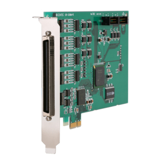
- Page 1 PC-HELPER High-Speed Up/Down Counter Board for PCI Express CNT-3208M-PE User’s Guide CONTEC CO., LTD.
-
Page 2: Check Your Package
Check Your Package Thank you for purchasing the CONTEC product. The product consists of the items listed below. Check, with the following list, that your package is complete. If you discover damaged or missing items, contact your retailer. Product Configuration List Board [CNT-3208M-PE] …1... -
Page 3: Copyright
No part of this document may be copied or reproduced in any form by any means without prior written consent of CONTEC CO., LTD. CONTEC CO., LTD. makes no commitment to update or keep current the information contained in this document. The information in this document is subject to change without notice. -
Page 4: Table Of Contents
Setting the Board ID .......................... 14 Setting the Logic of External Control Signals................. 14 Setting Terminators ........................... 15 Plugging the Board ..........................16 Step 3 Installing the Hardware ......................... 17 Turning on the PC ..........................17 Found New Hardware Wizard Setting ....................18 CNT-3208M-PE... - Page 5 Single-phase Input with Gate Control Attached ................42 Multiplication of Count Input ......................43 Synchronous Clear ..........................43 Asynchronous Clear .......................... 44 Phase-Z/CLR Input ..........................44 Control of a counter ..........................45 Counter start/Counter stop ........................ 45 Preset ..............................46 CNT-3208M-PE...
- Page 6 ABOUT SOFTWARE About Software for Windows ........................65 Accessing the Help File ........................65 Using Sample Programs ........................66 Uninstalling the Driver Libraries...................... 67 ABOUT HARDWARE For detailed technical information ......................69 Hardware specifications..........................69 Block Diagram ............................73 CNT-3208M-PE...
- Page 7 CNT-3208M-PE...
-
Page 8: Before Using The Product
10MHz. In addition, 2-phase signals and 1-phase signals such as a rotary encoder or linear scale can be counted. With the driver libraries for Windows supplied as standard, applications with CONTEC hardware features fully utilized can be created. - Page 9 The synchronization control connectors are provided The synchronization control connectors which can make boards up to 16 pieces synchronously run are provided. In addition, the synchronous operation with CONTEC boards where a synchronization control connector is mounted can be easily realized.
-
Page 10: Support Software
1. Before Using the Product Support Software You should use CONTEC support software according to your purpose and development environment. Windows version of counter input driver API-CNT(WDM) / API-CNT(98/PC) [Stored on the bundled disk driver library API-PAC(W32)] The API-CNT(WDM) / API-CNT(98/PC) is the Windows version driver library software that provides products in the form of Win32 API functions (DLL). -
Page 11: Customer Support
You can download updated driver software and differential files as well as sample programs available in several languages. Note! For product information Contact your retailer if you have any technical question about a CONTEC product or need its price, delivery time, or estimate information. Limited Three-Years Warranty CONTEC product are warranted by CONTEC Co., LTD. -
Page 12: Safety Precautions
WARNING indicates a potentially hazardous situation which, if not avoided, could WARNING result in death or serious injury. CAUTION indicates a potentially hazardous situation which, if not avoided, may CAUTION result in minor or moderate injury or in property damage. CNT-3208M-PE... -
Page 13: Handling Precautions
Even when using the product continuously, be sure to read the manual and understand the contents. Do not modify the product. CONTEC will bear no responsibility for any problems, etc., resulting from modifying this product. Regardless of the foregoing statements, CONTEC is not liable for any damages whatsoever (including damages for loss of business profits) arising out of the use or inability to use this CONTEC product or the information contained herein. -
Page 14: Environment
(3) Store the package at room temperature at a place free from direct sunlight, moisture, shock, vibration, magnetism, and static electricity. Disposal When disposing of the product, follow the disposal procedures stipulated under the relevant laws and municipal ordinances. CNT-3208M-PE... - Page 15 1. Before Using the Product CNT-3208M-PE...
-
Page 16: Setup
Using the Board under an OS Other than Windows For using the board under an OS other than Windows, see the following parts of this user’s guide. This chapter Step 2 Setting the Hardware Chapter 3 External Connection Chapter 6 About Hardware CNT-3208M-PE... -
Page 17: Step 1 Installing The Software
This section describes how to install the Driver libraries. Before installing the hardware in a PC, install "Driver Library API-PAC(W32)" from the bundled media or download and install the latest edition of this software from the CONTEC web site. Although some user interfaces are different depending on the OS used, the basic procedure is the same. - Page 18 (2) The API-PAC(W32) Installer window appears automatically. If the panel does not appear, run (drive letter):\AUTORUN.exe. (3) Click on the [Install Development or Execution Environment] button. CAUTION Before installing the software in Windows 2000 or later, log in as a user with administrator privileges. CNT-3208M-PE...
- Page 19 (3) Click on the [Install] button. Clicking the [API-CNT] button displays detailed information about API-CNT(WDM) and API-CNT(98/PC). Run the installation (1) Complete the installation by following the instructions on the screen. (2) The Readme file appears when the installation is complete. CNT-3208M-PE...
-
Page 20: Step 2 Setting The Hardware
Note that the switch setting shown below is the factory default. - Synchronization control connector - Board ID setting - Terminator setting (CN2, CN3) switch switch (SW3 - SW6) BOARD ID CNT-3208M-PE BOARD ID - Output signal logic - Interface connector setting switch (CN1) (SW2) Figure 2.1. Component Locations CNT-3208M-PE... -
Page 21: Setting The Board Id
To set the logic for output signals, use the on-board DIP switch (SW2). See Figure 2.3 below to set the SW2. Channel Negative logic Positive logic 1 2 3 4 5 6 7 8 Factory setting: All ON Figure 2.3. Board ID Settings (SW2) CNT-3208M-PE... -
Page 22: Setting Terminators
---- Phase-A Phase-B Phase-Z N.C. ---- ---- Figure 2.4. Terminator Setting Switches and Their Settings CAUTION For those channels which do not use the differential line receiver input or for unused input signals, select “Do not insert the terminator”. CNT-3208M-PE... -
Page 23: Plugging The Board
Be sure that the personal computer or the I/O extension unit power is turned off. Make sure that your PC or extension unit can supply ample power to all the boards installed. Insufficiently energized boards could malfunction, overheat, or cause a failure. CNT-3208M-PE... -
Page 24: Step 3 Installing The Hardware
If you remove two or more boards that have already been installed and then remount one of them on the computer, it is unknown that which one of the sets of resources previously assigned to the two boards is assigned to the remounted board. In this case, you must check the resource settings. CNT-3208M-PE... -
Page 25: Found New Hardware Wizard Setting
(2) When the model name of hardware is displayed, select “Install the software automatically [Recommended]” and then click on the “Next” button. The device is automatically installed, and processing is completed. You have now finished installing the initial setting of Hardware. CNT-3208M-PE... -
Page 26: Step 4 Initializing The Software
- CNT-3208M-PE (2) The installed hardware appears under the CONTEC Devices node. Open the CONTEC Devices node and select the device you want to setup (the device name should appear highlighted). Click [Properties]. CNT-3208M-PE... - Page 27 - CNT-3208M-PE The initial device name that appears is a default value. You can use this default name if you wish. Make sure that you do not use the same name for more than one device.
-
Page 28: Step 5 Operation Checks
Set the board in the default factory. To connect an external device, see Chapter 3 “External Connection”. Starting the Diagnosis Program Open the “Properties” page of the device that was used for the software initialization, and press the [Diagnosis] button. CNT-3208M-PE... - Page 29 (2) Set the counter mode for channel 0. Set “Signal Source” to “Line receiver”. Leave the other settings at factory defaults. Click on [Use Same Mode] to make the same settings for the other channels. Set up ”Line receiver” Click on [Use Same Mode]. CNT-3208M-PE...
- Page 30 2. Setup (3) Click on the [End] button to finish condition setting. Click on [End]. CNT-3208M-PE...
- Page 31 [Zero Clear] Clears the counter to zero. [Counter Stop] Stops the counter. (1) Click on [Counter Start]. Click on [Counter Start]. (2) The counter value of each channel is displayed along with its status (ALM, AI, U, A, B, Z). CNT-3208M-PE...
- Page 32 The frequency of test pulse is fixed at 100 kHz. The board can also internally output test pulses to each counter channel without supplying them to the outside. In that case, the board outputs two-phase pulses to all channels at the same time. CNT-3208M-PE...
- Page 33 "driver file test", " Board setting test". CAUTION Before executing diagnosis report output, unplug the cable from the board. Click on [Diagnosis Report…] (2) A diagnosis report is displayed as shown below. * The name of the board you have tested is displayed. - CNT-3208M-PE CNT-3208M-PE...
-
Page 34: Setup Troubleshooting
Diagnosis Program, it will work with other applications. Review the program, paying attention to the following points. Check the return values of functions. Refer to the source code of sample program. Refer to the “Troubleshooting” in API-TOOL(WDM) HELP (APITOOL.chm) CNT-3208M-PE... - Page 35 2. Setup CNT-3208M-PE...
-
Page 36: External Connection
PCR-E96LMD [mfd.by HONDA TSUSHIN KOGYO CO.,LTD.] equivalent - Applicable connector PCR-E96FA [mfd.by HONDA TSUSHIN KOGYO CO.,LTD.] equivalent * Please refer to chapter 1 for more information on the supported cable and accessories. Figure 3.1. Interface Connector (CN1) Shape CNT-3208M-PE... -
Page 37: Connector Pin Assignment
*1 The control inputs can serve as the general-purpose, counter start/stop, preset, and zero-clear inputs. *2 The control outputs can serve as the general-purpose output, count match, abnormal input error, digital filter error, and discontinuity alarm error outputs. Figure 3.2. Pin Assignment of an interface connector (CN1) CNT-3208M-PE... -
Page 38: External Device Connection 1 -Differential Line Receiver Input
PWL : Low-level count input pulse width 50nsec (Min.) Figure 3.4. Input signal CAUTION In the input pin+, TTL level input circuit is parallel-connected. Please use the shielded cable with a length of less than 30m to meet “CE EMC Directive”. CNT-3208M-PE... -
Page 39: Example Connection With A Rotary Encoder
3. External Connection Example Connection with a Rotary Encoder Power supply (Connector pin No.) Phase-A+ Phase-A+ (A17) CNT-3208M-PE Phase-A- Phase-A- (A18) Phase B+ Phase B+ (A19) Phase-B- (A20) Phase-B- Encorder Phase-Z+ (A21) Phase-Z+ Phase-Z- (A22) Phase-Z- (A23) Shield Figure 3.5. Example Connection with a Rotary Encoder (differential line receiver input, Channel 0) -
Page 40: External Device Connection 2 -Ttl Level Input
To prevent noise from causing a malfunction, arrange the connection cable as away from any other signal conductor or noise source as possible. In the input pin+, TTL level input circuit is parallel-connected. Please use the shielded cable to meet “CE EMC Directive”. CNT-3208M-PE... -
Page 41: Example Connection With A Rotary Encoder
3. External Connection Example Connection with a Rotary Encoder Power supply (Connector pin No.) Phase-A (A17) Phase-A CNT-3208M-PE Phase-B (A19) Phase-B Phase-Z (A21) Phase-Z Encoder GND (A23) Shield Figure 3.9. Example Connection with a Rotary Encoder (TTL level input, channel 0) -
Page 42: Connecting The Control Signal Input/Output
The connection cable length should be within 1.5 m. To prevent noise from causing a malfunction, arrange the connection cable as away from any other signal conductor or noise source as possible. Please use the shielded cable to meet “CE EMC Directive”. CNT-3208M-PE... - Page 43 Control input signal can be selected with whether to enable rise or fall by software at the TTL level. High- and low-level hold times of at least 50 nsec are required to detect an edge of the signal. HIH : High-level hold time 50nsec (Min.) HIL : Low-level hold time 50nsec (Min.) Figure 3.13. Control input signals CNT-3208M-PE...
-
Page 44: Connection Of A Control Output
The output of this board has no surge voltage protector. To drive an inductive load such as a relay or lamp using this board, apply surge voltage protection to the load side. For surge voltage protection, see “Surge Voltage Countermeasures” in the next section. Please use the shielded cable to meet “CE EMC Directive”. CNT-3208M-PE... -
Page 45: Surge Voltage Countermeasures
Output pin Output pin Dark-lighting bypass resistor Ground Ground Figure 3.16. Surge Voltage Countermeasures CAUTION In order for a protection circuit to operate effectively, it must be connected within 50 cm of a load and a contact point. CNT-3208M-PE... -
Page 46: Using Two Or More Boards Synchronously
(5) Start the slave boards first, then the master board. CAUTION When the clock signal is assigned to a synchronization control connector, the maximum clock frequency available is 5 MHz. When signals are assigned to synchronization control connectors, the slave boards have a delay of about 100 nsec. CNT-3208M-PE... -
Page 47: Connecting The Synchronization Control Connectors (Cn2 And Cn3)
(5) Start the slave boards first, then the master board. Connecting the synchronization control connectors (CN2 and CN3) The CNT-3208M-PE has synchronization control connectors (CN2 and CN3) to accept synchronization control cables for synchronous operations of two or more boards. Connection method For synchronous operations of two or more boards, connect them with synchronization control cables. -
Page 48: Functions
* The minimum phase difference between phases-A and B is 25 nsec. Counting is not performed normally if the phase difference is less than 25 nsec. Figure 4.1. Example counting during 2-phase input CNT-3208M-PE... -
Page 49: Single-Phase Input
(phase-A/UP) while the gate control signal (phase-B/DOWN) goes high and stops counting while the gate control signal goes low. Figure 4.3. Example counting during single-phase input with gate control attached CNT-3208M-PE... -
Page 50: Multiplication Of Count Input
(Phase-Z/CLR) Count value * When decremental counting in the CW direction is set, the board performs decremental counting at the rising edge of the phase-A signal while the phase-B input remains low. Figure 4.5. Example counting during synchronous clear CNT-3208M-PE... -
Page 51: Asynchronous Clear
Figure 4.7. Phase-Z enable frequency (Positive logic) CAUTION The initial setting is “only the next phase-Z input is enabled once”. Phase-Z (negative logic) is enabled while the phase-Z input goes low. When the phase-Z/CLR input is not used, be sure to disable the phase-Z input. CNT-3208M-PE... -
Page 52: Control Of A Counter
Sampling start/stop When the counter start trigger is used for starting sampling, this product starts counting and sampling synchronously. When the counter stop trigger is used for stopping sampling, this product stops counting and sampling synchronously in the same way. CNT-3208M-PE... -
Page 53: Preset
When the control input pin is used for presetting, it cannot be used for the counter start/stop, zero- clear, or general-purpose input. Count match The counter is preset when the count value matches the value in comparison register 0 or 1. CNT-3208M-PE... -
Page 54: Zero-Clear
The preset register is a 32-bit register to load the value in the preset register to the counter when presetting occurs. Comparison register 0, Comparison register 1 These are 32-bit registers. A variety of events can occur when the counter value matches the value in comparison register 0 or 1. CNT-3208M-PE... -
Page 55: Obtaining The Count Value
A one-shop pulse can be output to the control input signal at an occurrence of a count match or error. Counter start Counter stop Pulse incoming signal Sampling clock Count value Sampling value Nothing Nothing Nothing Nothing Figure 4.9. Timing chart (Counter mode) CNT-3208M-PE... -
Page 56: Sampling Mode
Pulse input signal Sampling clock Count value Sampling value Nothing Nothing Figure 4.10. Timing chart (Counter-asynchronous sampling mode) Sampling start Sampling stop Pulse incoming signal Sampling clock Count value Sampling value Nothing Figure 4.11. Timing chart (Counter- synchronous sampling mode) CNT-3208M-PE... -
Page 57: Totalizing/Line Receiver Counter
The totalizing or line receiver counter can be set for each channel. Totalizing counter mode Pulse incoming signal Sampling clock Count value Sampling value Nothing Differential counter mode Pulse incoming signal Sampling clock Count value Sampling value Nothing Figure 4.12. Totalizing/line receiver counter CNT-3208M-PE... -
Page 58: Sampling Function
If transfer is terminated with an error such as failure to acquire the bus or transfer data in time, this product stops transfer and generates a transfer completion interrupt. The occurrence of any transfer error can be detected by checking the status. CNT-3208M-PE... -
Page 59: Status, Count
The 32-bit or 64-bit transfer count can be obtained by using the relevant API-CNT(98/PC) function in API-PAC(W32). The transfer count is obtained as the number of data items (per channel) which have been transferred to the memory area for the user application. CNT-3208M-PE... -
Page 60: Control Of A Sampling
The sampling clock can be set to a minimum of 50 ns assuming that only one channel is subject to sampling. For sampling for more channels, the minimum sampling clock must be set to “the number of sampling channels x 50 nsec”. Example: Minimum sampling clock for 8-channel sampling = 8 x 50 nsec = 400 nsec CNT-3208M-PE... -
Page 61: Hardware Event
When the control output signal is used as a general-purpose output, it becomes a level output and hardware events cannot be set as above. The output signal logic is set with the SW2 on this product. For setting the logic, see “Setting the Logic of External Control Signals” in Chapter 2. CNT-3208M-PE... -
Page 62: Control Input Signal
When the control input signal is set to counter start/stop, the control input pin serves as the external trigger input pin for counter start/stop. The rising or falling edge of the signal can be selected for each of the counter start and counter stop. CNT-3208M-PE... -
Page 63: Control Output Signal
Both of the inputs go high upon detection of discontinuity or an alarm output from the differential line receiver input circuit. It can be switched between positive logic and negative logic. CNT-3208M-PE... -
Page 64: Count Match
- A one-shot pulse is output with count value = comparison register 1. Counter start Event at (1) (Agrees with comparison register 0) - A one-shot pulse is output with count value = comparison register 0. Figure 4.13. Example 1 CNT-3208M-PE... - Page 65 Check the interrupt status and, if COMP0 contains 1, set comparison register 0 to 300. Counter - Reset COMP0 to 0. *2 start *1 Time required between events: About 5 ms (depending on the system configuration) *2 COMP0 :Count match(register 0)Status COMP1 :Count match(register 1)Status Figure 4.15. Example 3 CNT-3208M-PE...
-
Page 66: Counter Error
When the signal is less than 200 nsec, a filter error is reported. Phase-A/Phase-B input signal When the signal is not less than 200 nsec, counting is performed normally. Phase-A/Phase-B input signal 100nsec Filter source clock Figure 4.16. Filter error (Set to 0.2 μsec) CNT-3208M-PE... - Page 67 Phase-A input Phase-B input No abnormal input error is reported when the phase difference is longer than the filter source clock cycle. Phase-A input Phase-B input Filter source clock Figure 4.17. Abnormal input error CNT-3208M-PE...
- Page 68 B both at High level Phase-A + Phase-A - Phase-B + Phase-B - Error detected with both positive and negative sides remaining at High level for 200 nsec Phase-Z + Phase-Z - One-shot pulse output External output Status Figure 4.18. Disconnection alarm error CNT-3208M-PE...
-
Page 69: Status Input
The counter is set to [1] when decremented from 0H to FFFFFFFFh. Count match A count match (to register 0), count match (to register 1), incremental count match, or decremental count match for each channel can be checked by the status. CNT-3208M-PE... -
Page 70: Other Functions
If the level changes at a frequency shorter than the set time, the level change is ignored and the input is not counted correctly. Timer The timer can generate an interrupt at software-set intervals. The setting range is 1 - 6553 msec (in 1 ms increments). CNT-3208M-PE... - Page 71 4. Functions CNT-3208M-PE...
-
Page 72: About Software
From the Start menu, click "CONTEC API-PAC(W32)" - "API-TOOL(WDM) HELP". When this link does not exist, From the Start menu, click "CONTEC API-PAC(W32)" - "API-CNT(WDM)" - "API-CNT(WDM) HELP". * For the API-CNT(98/PC) driver, From the Start menu, click "CONTEC API-PAC(W32)" - "API-CNT(98/PC)" - "API-CNT HELP". CNT-3208M-PE... -
Page 73: Using Sample Programs
(1) Click on the [Start] button on the Windows taskbar. (2) For the API-CNT(WDM), from the Start Menu, go to “Programs”, and select the sample program you wish to launch from the list of “CONTEC API-CNT(WDM)”. (3) A sample program is invoked. -
Page 74: Uninstalling The Driver Libraries
Use [My Computer] - [Control Panel] - [Programs and Features] to uninstall the development environment. In case of API-***(WDM), select [CONTEC API-***(WDM) VerX.XX (Develop)] and then click [Uninstall]. * "***" contains the driver category name (AIO, CNT, DIO, SMC, etc.). - Page 75 5. About Software CNT-3208M-PE...
-
Page 76: About Hardware
This chapter provides hardware specifications and hardware-related supplementary information. For detailed technical information For further detailed technical information (“Technical Reference” including the information such as an I/O map, configuration register, etc.), visit the Contec's web site (http://www.contec.com/support/) to call for it. Hardware specifications Table 6.1. - Page 77 Output rating Response speed (Max.) 5µsec One line receiver output for each of phases-A and B Test pulse output signal (For TTL level output, use the positive line receiver output.) Element in use Equivalent to AM26LS31 (T.I) 100kHz Frequency CNT-3208M-PE...
- Page 78 *2 Please use the shielded cable with a length of less than 30m to meet “CE EMC Directive”. *3 Please use the shielded cable to meet “CE EMC Directive”. Board Dimensions 169.33(L) [mm] The standard outside dimension (L) is the distance from the end of the board to the outer surface of the slot cover. CNT-3208M-PE...
- Page 79 440BX/PentiumII450MHz 13.4 i820/PentiumIII800MHz 13.4 i815E/PentiumIII800MHz 13.4 [MHz] ”Limited” indicates that the number of transfers is specified; “Unlimited” specifies that it is not specified. These values may not be satisfied depending on the system configuration including other boards and applications. CNT-3208M-PE...
-
Page 80: Block Diagram
Master Command setting register Control Logic Counter read register 32 bit counter Initial value storage register Comparison setting register Direct Read Each control register External control Sampling control / synchronization signal control Synchronization control connector Figure 6.1. Block Diagram CNT-3208M-PE... - Page 81 CONTEC CO., LTD. August 2017 Edition 3-9-31, Himesato, Nishiyodogawa-ku, Osaka 555-0025, Japan https://www.contec.com/ No part of this document may be copied or reproduced in any form by any means without prior written consent of CONTEC CO., LTD. [08252017] [10242006] Management No. A-51-307 [08252017_rev5] Parts No.