Table of Contents

Related Manuals for Contec COM-1(LPCI)H


Summary of Contents for Contec COM-1(LPCI)H
- Page 1 PC-HELPER RS-232C 1ch Serial I/O Board for Low Profile PCI COM-1(LPCI)H RS-232C 2ch Serial I/O Board for Low Profile PCI COM-2(LPCI)H RS-232C 4ch Serial I/O Board for Low Profile PCI COM-4(LPCI)H User’s Guide CONTEC CO.,LTD.
- Page 2 Check Your Package Thank you for purchasing the CONTEC product. The product consists of the items listed below. Check, with the following list, that your package is complete. If you discover damaged or missing items, contact your retailer. Product Configuration List...
-
Page 3: Copyright
No part of this document may be copied or reproduced in any form by any means without prior written consent of CONTEC CO., LTD. CONTEC CO., LTD. makes no commitment to update or keep current the information contained in this document. The information in this document is subject to change without notice. -
Page 4: Table Of Contents
Plugging the Board ........................15 Step 2 Installing the Hardware ......................16 Turning on the PC........................16 Windows 8, 7 ..........................17 Windows Server 2008, Windows Vista ..................19 Windows Server 2003, Windows XP, Windows 2000 ............. 20 COM-1(LPCI)H, COM-2(LPCI)H, COM-4(LPCI)H... - Page 5 Symptoms and Actions ......................28 If your problem cannot be resolved................... 28 EXTERNAL CONNECTION In the case of COM-1(LPCI)H ......................29 Connecting it directly from the on-board connector ..............29 In the case of COM-2(LPCI)H ......................30 Using the 9-pin D-SUB Connector Conversion Cables ............30 Connecting it directly from the on-board connector ..............
- Page 6 ABOUT HARDWARE For detailed technical information ....................45 Hardware specification ........................46 Differences between the COM-1(LPCI)H, COM-2(LPCI)H and COM-4(LPCI)H ....... 49 COM-1(LPCI)H, COM-2(LPCI)H, COM-4(LPCI)H...
- Page 7 COM-1(LPCI)H, COM-2(LPCI)H, COM-4(LPCI)H...
-
Page 8: Before Using The Product
921,600bps. It also comes with a Windows/Linux driver, which allows boards to be used as OS-standard COM ports. This product supports CONTEC-defined driver library “API-PAC(W32)” that provide local routines. Features - Max. 921,600bps RS-232C Serial Communication The <... - Page 9 - To suit your application, cables and connectors are available as optional COM-1(LPCI)H : Straight cables (1.8m), cross cables (1.8m) and 9-pin D-SUB connectors (male or female type) for your own cables are available as optional.
-
Page 10: Support Software
Standard COM Driver Software COM Setup Disk (Bundled) The purpose of this software is to allow the CONTEC serial communication boards to be used under Windows or Linux in the same way as the standard COM ports on the PC. By installing additional boards, you can use COM ports in the range COM1 - COM256. -
Page 11: Cable & Connector (Option)
: CN5-D9F D-SUB25P Male Connector Set (5 Pieces) : CN5-D25M D-SUB25P Female Connector Set (5 Pieces) : CN5-D25F D-SUB44P Male Connector Set (5 Pieces) : CN5-D44M Check the CONTEC’s Web site for more information on these options. COM-1(LPCI)H, COM-2(LPCI)H, COM-4(LPCI)H... -
Page 12: Customer Support
You can download updated driver software and differential files as well as sample programs available in several languages. Note! For product information Contact your retailer if you have any technical question about a CONTEC product or need its price, delivery time, or estimate information. Limited Three-Years Warranty CONTEC Interface boards are warranted by CONTEC CO., LTD. -
Page 13: Safety Precautions
WARNING indicates a potentially hazardous situation which, if not avoided, could WARNING result in death or serious injury. CAUTION indicates a potentially hazardous situation which, if not avoided, may CAUTION result in minor or moderate injury or in property damage. COM-1(LPCI)H, COM-2(LPCI)H, COM-4(LPCI)H... -
Page 14: Handling Precautions
Even when using the product continuously, be sure to read the manual and understand the contents. Do not modify the product. CONTEC will bear no responsibility for any problems, etc., resulting from modifying this product. Regardless of the foregoing statements, CONTEC is not liable for any damages whatsoever (including damages for loss of business profits) arising out of the use or inability to use this CONTEC product or the information contained herein. -
Page 15: Environment
(3) Store the package at room temperature at a place free from direct sunlight, moisture, shock, vibration, magnetism, and static electricity Disposal When disposing of the product, follow the disposal procedures stipulated under the relevant laws and municipal ordinances. COM-1(LPCI)H, COM-2(LPCI)H, COM-4(LPCI)H... -
Page 16: Setup
API-SIO in the "Driver Library API-PAC(W32)". If using API-SIO from API-PAC(W32), install from API-PAC(W32) instead of from the supplied CD-ROM. See also the following parts of this manual as required. This chapter Step 1 Setting the Hardware COM-1(LPCI)H, COM-2(LPCI)H, COM-4(LPCI)H... -
Page 17: Using The Board Under Linux Using The Standard Com Driver Software Com Setup Disk
This chapter Step 1 Setting the Hardware Operating Systems Other than Windows or Linux Refer to the following if using on an OS other than Windows or Linux. This chapter Step 1 Setting the Hardware Chapter 4 Functions Chapter 6 About Hardware COM-1(LPCI)H, COM-2(LPCI)H, COM-4(LPCI)H... -
Page 18: Step 1 Setting The Hardware
Remove the screws and replace the low-profile PCI bracket with the standard PCI bracket. Bracket for the Low Profile PCI Screw Use a flathead screwdriver or hexagonal spanner to undo and tighten the screws. Figure 2.1. Replacing the Bracket COM-1(LPCI)H, COM-2(LPCI)H, COM-4(LPCI)H... -
Page 19: Parts Of The Board And Factory Defaults
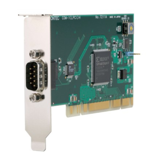
Board ID setting switch (SW1) BOARD ID COM-1(LPCI)H BOARD ID - PCI bus slot power voltage setting jumper 1 2 3 Figure 2.2. Component Locations < COM-1(LPCI)H > COM-2(LPCI)H - Interface connector (CN1) Board ID setting switch (SW1) BOARD ID COM-2(LPCI)H... - Page 20 2. Setup COM-4(LPCI)H - Interface connector (CN1) Board ID setting switch (SW1) BOARD ID COM-4(LPCI)H BOARD ID - PCI bus slot power voltage setting jumper 1 2 3 Figure 2.4. Component Locations < COM-4(LPCI)H > COM-1(LPCI)H, COM-2(LPCI)H, COM-4(LPCI)H...
-
Page 21: Setting The Board Id
When 5 V power is supplied, set the JP1 to the 2-3 connected state (factory default). If 5 V power is not supplied, set the JP1 to the 1-2 connected state. If outputting 5V power supply If not outputting 5V power supply 1 2 3 1 2 3 (Factory setting) Figure 2.6. Setting the Supply Voltage COM-1(LPCI)H, COM-2(LPCI)H, COM-4(LPCI)H... -
Page 22: Plugging The Board
Doing so could cause trouble. Be sure that the personal computer or the I/O expansion unit power is turned off. Make sure that your PC or expansion unit can supply ample power to all the boards installed. Insufficiently energized boards could malfunction, overheat, or cause a failure. COM-1(LPCI)H, COM-2(LPCI)H, COM-4(LPCI)H... -
Page 23: Step 2 Installing The Hardware
If you remove two or more boards that have already been installed and then remount one of them on the computer, it is unknown that which one of the sets of resources previously assigned to the two boards is assigned to the remounted board. In this case, you must check the resource settings. COM-1(LPCI)H, COM-2(LPCI)H, COM-4(LPCI)H... -
Page 24: Windows 8, 7
[Properties] button. *1 Please search for “Devices and Printers” case of Windows 8. * The category of the board you have just added is displayed. - PCI Serial Port (or “PCI Simple Communication Controller”) COM-1(LPCI)H, COM-2(LPCI)H, COM-4(LPCI)H... - Page 25 (3) The Driver Installation Wizard is open. Click “Browse my computer for driver software”. (4) Specify that folder on the CD-ROM which contains the setup information (INF) file to register the board. - Source folder \PCI \ComDrv You have now finished installing the hardware. COM-1(LPCI)H, COM-2(LPCI)H, COM-4(LPCI)H...
-
Page 26: Windows Server 2008, Windows Vista
- PCI Serial port (2) When the “Found New Hardware” window is displayed, insert the accompanying CD-ROM “COM Setup Disk” into the CD-ROM drive. After a while, the device installation process begins. You have now finished installing the hardware. COM-1(LPCI)H, COM-2(LPCI)H, COM-4(LPCI)H... -
Page 27: Windows Server 2003, Windows Xp, Windows 2000
(2) Specify that folder on the CD-ROM which contains the setup information (INF) file to register the board. - Source folder \PCI\ComDrv * The name of the board you have just added is displayed. - COM-1(LPCI)H - COM-2(LPCI)H - COM-4(LPCI)H COM-1(LPCI)H, COM-2(LPCI)H, COM-4(LPCI)H... -
Page 28: The Check Method Of The Completion Of Hardware Installation
(1) Select "System" from "Control Panel" and open [Device Manager]. (2) Check that the names of the boards you are using are registered correctly in the [Multifunction adapters] folder. (3) Similarly, confirm that the COM ports have been added in the [Ports] folder. COM-1(LPCI)H, COM-2(LPCI)H, COM-4(LPCI)H... -
Page 29: Step 3 Initializing The Software
(1) Select "System" from "Control Panel" and start [Device Manager]. * The name of the board you have just added is displayed. - COM-1(LPCI)H - COM-2(LPCI)H - COM-4(LPCI)H (2) Check that the new COM ports are displayed in the [Ports] folder. COM-1(LPCI)H, COM-2(LPCI)H, COM-4(LPCI)H... - Page 30 - By selecting the “Compulsion Half-Duplex”, the software settings are forced to switch from full-duplex communication to half-duplex. - By selecting the “Used Serial Mice”, support for the serial mouse devices is enabled. You have now finished installing the initial setting of Software. COM-1(LPCI)H, COM-2(LPCI)H, COM-4(LPCI)H...
-
Page 31: For Use Under Windows Nt, Me, 98 Or 95
(1) Select “Save settings to registry…” from the “File” menu. (2) After rebooting, the registered COM ports are now able to be used as standard COM ports. You have now finished installing the initial setting of Software. COM-1(LPCI)H, COM-2(LPCI)H, COM-4(LPCI)H... -
Page 32: Step 4 Checking Operations With The Diagnosis Program
Obtain an RS-232C cross cable. If you do not have a cross cable, you can use a switch on the board to perform testing of a single COM port using loopback communications. See the figure below for the switch settings. Switch setting for using a cross cable < 9pin > < 25pin > Board side Board side COM-1(LPCI)H, COM-2(LPCI)H, COM-4(LPCI)H... -
Page 33: Using The Diagnosis Program
When performing loopback communications on a single COM port, set the same port number in both [Device 1] and [Device 2]. Communication Settings: Specify the [Bits / Second], [Data bits] and other settings you wish to use. COM-1(LPCI)H, COM-2(LPCI)H, COM-4(LPCI)H... - Page 34 2. Setup Start test Click the [Start] button to start the test using the specified conditions. View test result The test result is displayed in the [Message] window. A successful completion message appears if the test completed OK. COM-1(LPCI)H, COM-2(LPCI)H, COM-4(LPCI)H...
-
Page 35: Setup Troubleshooting
Please only use the software that is applicable for your intended use. If the incorrect software is installed by mistake, please uninstall the incorrect software then install the correct software. If your problem cannot be resolved Contact your retailer. COM-1(LPCI)H, COM-2(LPCI)H, COM-4(LPCI)H... -
Page 36: External Connection
TxD1 Transmit Data Clear to Send CTS1 DTR1 Data Terminal Ready Ring Indicator Signal Ground Figure 3.2. Pin Assignments of Interface Connector < COM-1(LPCI)H > Cable (Option) RS-232C Straight Cable with D-SUB9P (1.8m) RSS-9M/F RS-232C Cross Cable with D-SUB9P (1.8m) -
Page 37: In The Case Of Com-2(Lpci)H
Connection Conversion Cable (44M→9M x 2, 250mm) PCE44/9P2S Cable (Option) RS-232C Straight Cable with D-SUB9P (1.8m) RSS-9M/F RS-232C Cross Cable with D-SUB9P (1.8m) RSC-9F RS-232C Connection Conversion Straight Cable (25M→9F, 1.8m) RSS-25M/9F RS-232C Connection Conversion Cross Cable (25F→9F, 1.8m) RSC-25F/9F COM-1(LPCI)H, COM-2(LPCI)H, COM-4(LPCI)H... -
Page 38: Connecting It Directly From The On-Board Connector
103A-44FGTBBB3 (mfd. by COXOC)equivalent - Applicable connector 101A-44MGTAAA3 (mfd. by COXOC, Male) CN5-D44M (mfd. by CONTEC, Male) (Five connector set) Figure 3.4. Interface Connector < COM-2(LPCI)H > Pin No. Signal name Pin No. Signal name Pin No. Signal name DCD1... -
Page 39: In The Case Of Com-4(Lpci)H
Connection Conversion Cable (44M→9M x 4, 250mm) PCE44/9P4S Cable (Option) RS-232C Straight Cable with D-SUB9P (1.8m) RSS-9M/F RS-232C Cross Cable with D-SUB9P (1.8m) RSC-9F RS-232C Connection Conversion Straight Cable (25M→9F, 1.8m) RSS-25M/9F RS-232C Connection Conversion Cross Cable (25F→9F, 1.8m) RSC-25F/9F COM-1(LPCI)H, COM-2(LPCI)H, COM-4(LPCI)H... -
Page 40: Connecting It Directly From The On-Board Connector
103A-44FGTBBB3 (mfd. by COXOC)equivalent - Applicable connector 101A-44MGTAAA3 (mfd. by COXOC, Male) CN5-D44M (mfd. by CONTEC, Male) (Five connector set) Figure 3.7. Interface Connector < COM-4(LPCI)H > Pin No. Signal name Pin No. Signal name Pin No. Signal name DCD1... -
Page 41: Types Of Cable And Example Connections
(Data Terminal Ready) (Data Set Ready) (Signal Ground) External device Figure 3.9. Example Connection to a Modem (Straight cable) External device Figure 3.10. Example Connection to a PC (Cross cable) External device Figure 3.11. Example Connection to a Device COM-1(LPCI)H, COM-2(LPCI)H, COM-4(LPCI)H... -
Page 42: Functions
Alternatively, setting a small FIFO trigger size or disabling FIFO operation increases the speed of data sending and receiving but increases the load on the CPU and risks received data being missed. As the FIFO trigger size is variable, you can adjust this setting to achieve optimum performance for your system. COM-1(LPCI)H, COM-2(LPCI)H, COM-4(LPCI)H... -
Page 43: Setting The Baud Rate
MSComm functionalities limits the rate to 115,200bps maximum. For setting the baud rate higher than 115,200bps using Visual Basic, refer to the VB sample program included in the accompanying CD-ROM “Standard COM Driver Software COM Setup Disk”. COM-1(LPCI)H, COM-2(LPCI)H, COM-4(LPCI)H... - Page 44 134.5 0.058 1713 0.0006 3426 0.0006 6852 0.0006 1536 3072 6144 1536 3072 1536 1200 1800 2000 0.68 0.17 0.17 0.04 2400 3600 4800 7200 9600 14400 19200 28800 38400 57600 76800 115200 153600 230400 460800 921600 COM-1(LPCI)H, COM-2(LPCI)H, COM-4(LPCI)H...
- Page 45 4. Functions COM-1(LPCI)H, COM-2(LPCI)H, COM-4(LPCI)H...
-
Page 46: About Software
Sends data entered from the keyboard and displays received data on the screen. Source folder: \Samples\VB.NET folder Visual C# 2005 sample programs (1) Transmit/Receive sample Sends data entered from the keyboard and displays received data on the screen. Source folder: \Samples \VCS folder COM-1(LPCI)H, COM-2(LPCI)H, COM-4(LPCI)H... - Page 47 5. About Software Visual C++ sample programs (1) Transmit sample Sends data entered from the keyboard. Execute from the command prompt. Source folder: \Samples\Vc\Comsend.c file (2) Receive sample Displays received data on the screen. Source folder: \Samples \Vc\Comread.c file COM-1(LPCI)H, COM-2(LPCI)H, COM-4(LPCI)H...
-
Page 48: Uninstalling The Driver Software
(2) Expand [Multifunction adapters] and delete [CONTEC Co., Ltd-XXXXXXXXXX] (installed hardware name). (3) Start [Add/Remove Programs] from the Control Panel. (4) Select [CONTEC COM-DRV(WDM) driver] from the list of applications, then click the [Add/Remove] button to automatically start the uninstall procedure. Windows 8, 7, Server 2008, Vista (1) Open the Control Panel and launch Device Manager from the [System] applet. -
Page 49: Windows Nt
Environment (1) Run SETUP.EXE from the API-PAC(W32) CD-ROM or from the file (* hereafter API-PAC(W32)) downloaded from the Contec's download site to install the API-SIO driver. (2) Reboot your OS, and the Hardware Wizard will be started. (3) During the installation, you will be prompted for an INF file. Specify the API-PAC(W32) INF folder designated for the OS and device type in use. -
Page 50: Cd-Rom Directory Structure
| |– VCS Sample program for VisualC.NET (for SerialPortClass) |– USB USB related files |– UsersGuide Manual of hardware (PDF) |– UTILITY Various utilities |– CommChk Self diagnostic program (Loopback communication test) |– CTstCom Self diagnostic program (Terminal utility) COM-1(LPCI)H, COM-2(LPCI)H, COM-4(LPCI)H... - Page 51 5. About Software COM-1(LPCI)H, COM-2(LPCI)H, COM-4(LPCI)H...
-
Page 52: About Hardware
This chapter provides hardware specifications and hardware-related supplementary information. For detailed technical information For further detailed technical information (“Technical Reference” including the information such as an I/O map, configuration register, etc.), visit the Contec's web site (http://www.contec.com/support/) to call for it. COM-1(LPCI)H, COM-2(LPCI)H, COM-4(LPCI)H... -
Page 53: Hardware Specification
The interrupt signals from all channels are connected as a single interrupt signal on the PCI bus. Boards with different board numbers are different in these specifications. See Table 6.4 "Different in the specification" at the end of this document. COM-1(LPCI)H, COM-2(LPCI)H, COM-4(LPCI)H... - Page 54 The interrupt signals from all channels are connected as a single interrupt signal on the PCI bus. Boards with different board numbers are different in these specifications. See Table 6.4 "Different in the specification" at the end of this document. COM-1(LPCI)H, COM-2(LPCI)H, COM-4(LPCI)H...
- Page 55 The interrupt signals from all channels are connected as a single interrupt signal on the PCI bus. Boards with different board numbers are different in these specifications. See Table 6.4 "Different in the specification" at the end of this document. Board Dimensions [ COM-1(LPCI)H, COM-2(LPCI)H, COM-4(LPCI)H ] 121.69(L) [mm]...
-
Page 56: Differences Between The Com-1(Lpci)H, Com-2(Lpci)H And Com-4(Lpci)H
6. About Hardware Differences between the COM-1(LPCI)H, COM-2(LPCI)H and COM-4(LPCI)H The COM-1(LPCI)H, COM-2(LPCI)H, and COM-4(LPCI)H are different in specifications, depending on the board number as listed below. Table 6.4. Different in the specification COM-1(LPCI)H Board No. No.7211 No.7211A No.7211B PCI bus specification... - Page 57 3-9-31, Himesato, Nishiyodogawa-ku, Osaka 555-0025, Japan Japanese http://www.contec.co.jp/ English http://www.contec.com/ Chinese http://www.contec.com.cn/ No part of this document may be copied or reproduced in any form by any means without prior written consent of CONTEC CO., LTD. [08302013] [04112003] Management No. A-46-740 [08302013_rev6] Parts No.