Table of Contents
Advertisement
Quick Links
Advertisement
Table of Contents

Related Manuals for Star Micronics BSC10 Series


Summary of Contents for Star Micronics BSC10 Series
- Page 1 THERMAL PRINTER BSC10 Series Hardware Manual...
- Page 2 Federal Communications Commission Radio Frequency Interference Statement This device complies with part 15 of the FCC Rules. Operation is subject to the following two conditions: (1) This device may not cause harmful interference, and (2) this device must accept any interference received, including interference that may cause undesired operation. FCC CAUTION: Changes or modifications not expressly approved by the party responsible for compliance could void the user's authority to operate the equipment.
- Page 3 • All efforts have been made to ensure the accuracy of the contents of this manual at the time of going to press. However, should any errors be detected, STAR would greatly appreciate being informed of them. • The above notwithstanding, STAR can assume no responsibility for any errors in this manual. © Copyright 2011-2017 Star Micronics Co., Ltd.
-
Page 4: Table Of Contents
TABLE OF CONTENTS 1. Unpacking and Installation .................1 1-1. Unpacking ........................1 1-2. Notes about Installation ....................1 2. Parts Identification and Nomenclature ..............2 3. Setup ........................4 3-1. Connecting the Interface Cable to the PC ..............4 3-2. Connecting the Interface Cable to the Printer ..............5 3-3. -
Page 5: Unpacking And Installation
1. Unpacking and Installation 1-1. Unpacking After unpacking the unit, check that all the necessary accessories are included in the package. Safety Instructions Printer * Accessories vary depending on the model and the region where the printer was purchased. 1-2. Notes about Installation 1. Choose a firm, level surface where the printer will not be exposed to vibration. -
Page 6: Parts Identification And Nomenclature
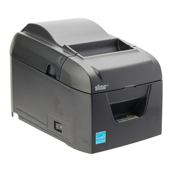
2. Parts Identification and Nomenclature Rear cover Open to replace paper. Do not open while printing. Control panel Features lamps that indicate printer status and a button for operating the printer. FEED button When the printer is online, pressing this button feeds the paper roll. POWER lamp (green) Lights when the printer is online. - Page 7 BSC10UC / BSC10UD ● DC24V BSC10LAN ● 100/10BASE DC OUT 5V/0.5A DIPSW DC24V 11 12 13 Power switch Turns the printer on and off. Interface connector Connects to a host PC through a cable. USB port Connects to a host PC through a USB cable. Power inlet Connects to an optional AC adapter.
-
Page 8: Setup
3. Setup 3-1. Connecting the Interface Cable to the PC 3-1-1. USB Cable Connect the USB cable to the USB port on your PC. 3-1-2. Parallel Cable Connect the parallel cable to the parallel port on your PC. 3-1-3. RS-232C Cable Connect the RS-232C cable to the RS-232C port on your PC. -
Page 9: Connecting The Interface Cable To The Printer
3-2. Connecting the Interface Cable to the Printer Printer cables are not included in the package. Obtain an appropriate cable that complies with the specifications beforehand. Because the appropriate interface cable differs depending on the system that you are connecting the printer to, contact the dealer that you bought the product from if you are unsure about what cable to use. Before connecting or disconnecting an interface cable, be sure to disconnect the AC adapter’s power cord from the outlet. - Page 10 3-2-2. Parallel Cable To connect a parallel cable, follow the procedure given below. 1) Make sure that the AC adapter’s power cord is not connected to the outlet. 2) Connect the parallel cable to the connector on the parallel interface board, and fasten the connector clasps. Parallel cable 3-2-3.
- Page 11 3-2-4. Ethernet Cable To connect the cable, follow the procedure given below. 1) Make sure that the AC adapter’s power cord is not connected to the outlet. 2) Connect the Ethernet cable to the Ethernet port. Ethernet cable ■ Link disconnection detection feature The Ethernet interface model is equipped with a link disconnection detection feature.
- Page 12 ■ About the Dip Switches You can use the dip switches to make the following settings for the Ethernet functions. Dip switch Function Set DHCP address acquisition timeout 20 seconds No Timeout Reset network settings (*1) Do not reset Reset By default, all settings are set to ON.
-
Page 13: Connecting The Ac Adapter
3-3. Connecting the AC Adapter Note: Before connecting or disconnecting the AC adapter, make sure that the printer and all the devices connected to it are turned off. Then remove the power cord from the outlet. 1) Connect the AC adapter to the power cord. Note: We recommend that you use the standard AC adapter and power cord. -
Page 14: Turning The Power On
3-4. Turning the Power On Connect the power cord according to the procedure in section 3-3, “Connecting the AC Adapter”. Turn on the power switch, which is on the left side of the printer. The POWER lamp on the control panel will light. Power switch 3-5. -
Page 15: Loading A Paper Roll
3-6. Loading a Paper Roll Use a paper roll that complies with the printer specifications. (See section 3-6-1, “Compliant Paper Roll Specifications”.) 1) Put your fingers in the grooves on either side of the printer, and open the rear cover. Rear cover Groove 2) Load the paper roll into the printer in the direction indicated by the figure, and pull the leading edge of the paper straight toward you. Note 1: Pull the paper straight as you pull it out. 2: Be careful not to pull the paper out at an angle, because doing so may cause the paper to jam or skew. Paper roll 3) Push on both sides of the rear cover to close it. - Page 16 3-6-1. Compliant Paper Roll Specifications Paper thickness 65 μm to 85 μm Paper width 79.5 ± 0.5 mm 57.5 ± 0.5 mm Note: Never change the paper width while the printer is in use. External dimensions • Roll diameter Max. 102 mm • Take up paper roll width +0.5 +0.5 mm / 58...
-
Page 17: Changing The Paper Width
3-7. Changing the Paper Width Move the paper roll guide to match the paper roll width. When you change the effective print width (paper roll width), change the printer utility’s memory switch setting. For details, see the printer utility help. * The following procedure is for changing the paper width from 80 mm to 58 mm. 1) Remove the paper roll guide. Paper roll guide 2) As shown in the figure, insert the paper roll guide in the groove. -
Page 18: Setup Precautions
3-8. Setup Precautions Caution Symbol These symbols are located near the thermal print head. Because the thermal print head is hot immediately after printing, do not touch it. Static electricity can damage the thermal print head. To protect the thermal print head from static electricity, do not touch it. - Page 19 Do not open the printer covers while the printer is printing or cutting. Do not pull out paper when the printer cover is closed. If liquid or foreign objects (such as coins and paper) enter the inside of the printer, turn the power switch off, disconnect the power cord from the AC outlet, and consult the dealer that you bought the product from. Continuing to use the printer may lead to a short-circuit, which may cause electric shock or fire.
-
Page 20: Led Display
4. LED Display 4-1. Error Indicators (1) Recoverable errors Check the recovery conditions. The printer can be recovered while maintaining its current status. Error description POWER ERROR Recovery condition Thermal head high temperature Flashes at The printer recovers automatically when the ther- detection error 1-second intervals mal head cools. -
Page 21: Preventing And Removing Paper Jams
5. Preventing and Removing Paper Jams 5-1. Preventing Paper Jams When you set the paper roll into the printer, do not pull out the end of the paper at an angle. Do not touch the paper roll when the printer is printing or feeding paper or before the cut operation has finished completely. Holding or pulling the paper while it is being fed may cause paper jams, improper cutting, or improper line breaks. Note: Do not remove the paper while it is being cut. -
Page 22: Releasing The Cutter Lock
5-3. Releasing the Cutter Lock If the auto cutter locks up, restart the printer by turning the power switch off and then back on. A typical locked cutter will be restored when you restart the printer. If restarting the printer does not release the locked cutter, follow the procedure below. Note: Be sure to turn off the printer before performing maintenance on the cutter. -
Page 23: Maintenance
6. Maintenance Accumulation of paper dust and dirt may cause the printer to not print portions of characters. To prevent such problems, perform periodic maintenance, such as removing paper dust from the paper transport section and removing the blackened paper dust from the thermal head surface. Note: Turn the printer’s power switch off before performing maintenance. - Page 24 Rev. 2.2 http://www.starmicronics.com/support/...