Zanussi ZGG66424 User Manual
Hide thumbs
Also See for ZGG66424:
- User manual (16 pages) ,
- User manual (16 pages) ,
- User manual (16 pages)
Table of Contents
Advertisement
Quick Links
Advertisement
Table of Contents

Related Manuals for Zanussi ZGG66424


Summary of Contents for Zanussi ZGG66424
- Page 1 User Manual GETTING STARTED? EASY. ZGG66424 EN User Manual...
-
Page 2: Safety Information
SAFETY INFORMATION Before the installation and use of the appliance, carefully read the supplied instructions. The manufacturer is not responsible for any injuries or damages that are the result of incorrect installation or usage. Always keep the instructions in a safe and accessible location for future reference. -
Page 3: Safety Instructions
CAUTION: The cooking process has to be supervised. A short • term cooking process has to be supervised continuously. WARNING: Danger of fire: Do not store items on the cooking • surfaces. Metallic objects such as knives, forks, spoons and lids should •... -
Page 4: Electrical Connection
appliance and the upper drawer, is sufficient for • Use only correct isolation devices: line air circulation. protecting cut-outs, fuses (screw type fuses • The underside of the appliance can get hot removed from the holder), earth leakage trips when in use. If an oven has not been fitted and contactors. - Page 5 • The vapours that very hot oil releases can cause • Discoloration of the enamel or stainless steel spontaneous combustion. has no effect on the performance of the • Used oil, that can contain food remnants, can appliance. cause fire at a lower temperature than oil used CARE AND CLEANING for the first time.
-
Page 6: Product Description
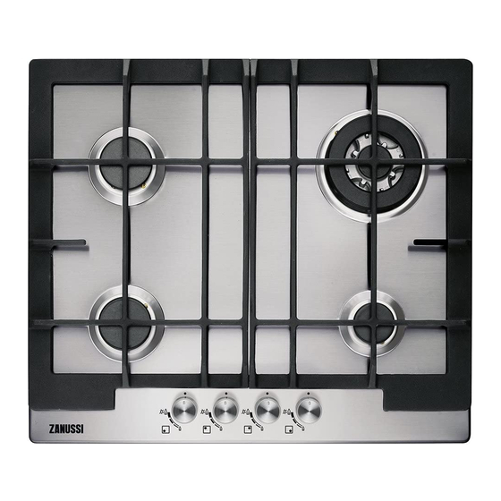
PRODUCT DESCRIPTION COOKING SURFACE LAYOUT Semi-rapid burner Triple Crown burner Auxiliary burner Control knobs CONTROL KNOB Symbol Description Symbol Description minimum gas supply no gas supply / off position ignition position / maximum gas supply DAILY USE WARNING! Refer to Safety chapters. -
Page 7: Burner Overview
BURNER OVERVIEW WARNING! Be very careful when you use open fire in the kitchen environment. The manufacturer declines any responsibility in case of the flame misuse. 1. Push the control knob down and turn it counterclockwise to the maximum gas supply position ( 2. -
Page 8: Hints And Tips
HINTS AND TIPS WARNING! Refer to Safety chapters. CAUTION! Make sure that the pots are placed centrally on the burner in order to get maximum stability and to get lower gas consumption. COOKWARE DIAMETERS OF COOKWARE CAUTION! Do not use cast iron pans, potstones, earthenware, grill or toaster Use cookware with diameters plates. -
Page 9: Periodic Maintenance
CLEANING THE HOB 4. For the burner to operate correctly, make sure that the arms of the pan supports are aligned • Remove immediately: melted plastic, plastic with the centre of the burner. foil, sugar and food with sugar. If not, the dirt can cause damage to the hob. -
Page 10: Labels Supplied With The Accessories Bag
Problem Possible cause Remedy The flame extinguishes immedi- Thermocouple is not heated up After lightning the flame, keep ately after ignition. sufficiently. the knob pushed for equal or less than 10 seconds. The flame ring is uneven. Burner crown is blocked with Make sure that the injector is food residues. -
Page 11: Important Safety Requirements
Model ........Make sure that, once the hob is installed, it is easily PNC ......... accessible for the engineer in the event of a Serial number ......breakdown. The manufacturer will not accept liability, should the IMPORTANT SAFETY REQUIREMENTS above instructions or any of the other safety This hob must be installed in accordance with the instructions incorporated in this instruction booklet Gas Safety (Installation and Use) Regulations... -
Page 12: Injectors Replacement
INJECTORS REPLACEMENT should be guided by means of clamps fixed to the side of the cabinet, in order to avoid any 1. Remove the pan supports. contact with the equipment beneath the 2. Remove the caps and crowns of the burner. cooktop. -
Page 13: Replacement Of The Connection Cable
1. Connect the green and yellow (earth) wire to the terminal which is marked with the letter 'E', or the earth symbol , or coloured green and yellow. 2. Connect the blue (neutral) wire to the terminal which is marked with the letter 'N' or coloured blue. - Page 14 min. 600 mm min. 650 mm min. 100 mm min. 55 mm 30 mm 560 mm 400 mm 50 mm If a furniture unit is installed at a distance of 400 mm above the hob, there must be a minimum safety distance of 50 mm to the left or right from the edge of the hob.
-
Page 15: Technical Data
POSSIBILITIES FOR INSERTION min 30 mm The panel installed below the hob must be easy to remove and let an easy access in case a technical assistance intervention is necessary. Kitchen unit with door or drawer min 5 mm (max 150 mm) 60 mm A. -
Page 16: Energy Efficiency
GAS BURNERS FOR NATURAL GAS G20 20 MBAR BURNER NORMAL POWER kW MINIMUM POWER kW INJECTOR MARK Triple Crown Semi-rapid 0,45 Auxiliary 0,33 GAS BURNERS FOR LPG G30/G31 28-30/37 MBAR NOMINAL GAS FLOW g/h NORMAL MINIMUM INJECTOR BURNER POWER kW POWER kW MARK G30 28-30 mbar... -
Page 17: Environmental Concerns
ENVIRONMENTAL CONCERNS the symbol with the household waste. Return the Recycle the materials with the symbol . Put the product to your local recycling facility or contact packaging in applicable containers to recycle it. your municipal office. Help protect the environment and human health and to recycle waste of electrical and electronic appliances. - Page 20 WWW.ZANUSSI.COM/SHOP...