Table of Contents
Advertisement
Available languages
Available languages
Quick Links
Advertisement
Table of Contents

Related Manuals for Hitachi Koki C 12LSH


Summary of Contents for Hitachi Koki C 12LSH
- Page 1 Slide Compound Miter Saw 滑動式多角度鋸機 슬라이드 콤파운드쏘 C 12LSH C 12RSH • Handling instructions 使用說明書 취급 설명서 Read through carefully and understand these instructions before use. 使用前務請詳加閱讀 본 설명서를 자세히 읽고 내용을 숙지한 뒤 제품을 사용하십시오.
-
Page 2: General Operational Precautions
18. Use outdoor extension leads. When tool is used GENERAL OPERATIONAL PRECAUTIONS outdoors, use only extension cords intended for outdoor use. WARNING! When using electric tools, basic safety 19. Stay alert. Watch what you are doing. Use common precautions should always be followed to reduce the risk sense. - Page 3 Gloves for handling saw blades (saw blades shall 44. Always cease operating the saw at once, if you be carried in a holder wherever practicable) and notice any abnormality whatsoever. rough material. 45. Always confirm that all components are mounted 15.
-
Page 4: Name Of Parts
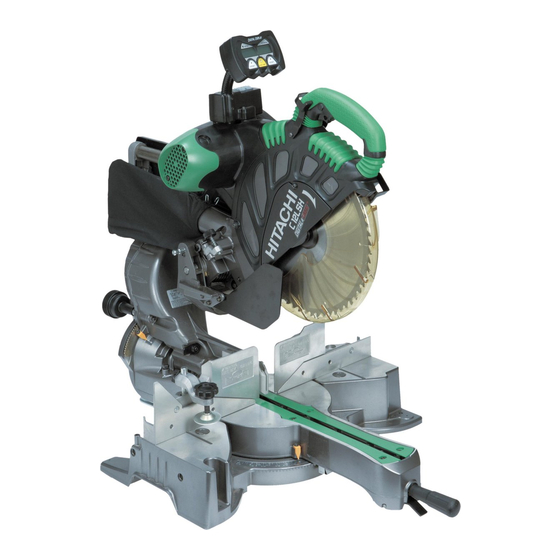
NAME OF PARTS Digital display Motor Nameplate Gear case (only C12LSH) Motor head Dust bag Handle Locking pin Hinge Spindle cover Holder (A) Rotation Clamp lever direction Laser marker Lower guard Knob (B) Indicator (For right bevel scale) Saw blade Sub fence (A) Set pin (A) Fence (A) -
Page 5: Specifications
SPECIFICATIONS Item Model C 12LSH / C 12RSH Motor Type Series commutator motor Voltage (Volts) (110V, 220V) Power input 1520 W Laser Marker Maximum output <1mW CLASS II Laser Product Wave length 400-700 nm Laser medium Laser Diode Precision ±0.5°... -
Page 6: Preparation Before Operation
When cutting the workpiece which has the dimension of PREPARATION BEFORE OPERATION “*” there might be some possibility of the lower end of the circular saw to touch with the workpiece, even if the Make the following preparations before operating the motor head is located at the lower limit position. -
Page 7: Before Using
2. Releasing the locking pin When the power tool is prepared for shipping, its main parts are secured by a locking pin. Move the handle slightly so that the locking pin can be disengaged. Handle Lower guard Fig. 7 Locking pin WARNING NEVER OPERATE THE POWER TOOL if the lower Pull... -
Page 8: Before Cutting
Table inserts are installed on the turntable. When BEFORE CUTTING shipping the tool from the factory, the table inserts are so fixed that the saw blade does not contact them. 1. Cutting a groove on the guard The burr of the bottom surface of the workpiece is Holder (A) has a guard (see Fig. - Page 9 (1) Turn the 8 mm depth adjustment bolt, change the Turn Right bevel angle cutting Left bevel angle height where the bolt head and the hinge contacts, Direct angle cutting cutting and adjust the lower limit position of the saw blade. NOTE Confirm that the saw blade is adjusted so that it will not cut into the turntable.
- Page 10 9. Installing the holders (Optional accessory) (2) Miter cutting and compound cutting The holders help keep longer workpieces stable and (Miter cutting + bevel cutting) in place during the cutting operation. Upon lowering the motor section, the lower guard is (1) As indicated in Fig.
- Page 11 (1) Light up the laser marker and make a groove of about 5 mm deep on the workpiece that is about 20 mm in height and 150 mm in width. Hold the grooved workpiece by vise as it is and do not move it. For grooving work, refer to “13.Groove cutting procedures”...
- Page 12 NOTE Check and make sure on a periodic basis if the position of the laser line is in order. As regards the checking method, draw a right-angle ink line on the workpiece with the height of about 20 mm and the width of 150 mm, and check that the laser line is in line with the ink line [The deviation between the ink line and the laser line should be less than the ink line width (0.5...
-
Page 13: Practical Applications
WARNING PRACTICAL APPLICATIONS Always firmly clamp or vise to secure the workpiece to the fence; otherwise the workpiece might be thrust WARNING from the table and cause bodily harm. To avoid personal injury, never remove or place a CAUTION workpiece on the table while the tool is being Always confirm that the motor head (see Fig. - Page 14 1 Pull forward Continued cutting operation can result in overload of the motor. Touch the motor and if it's hot, stop your 3 Push rearward cutting operation once and rest for 10 minutes or so, to cut Handle and then restart your cutting operation. Do not operate the head section or lift up the main unit while grasping the digital display (Fig.
- Page 15 Loosen Tighten Clamp Lever Clamp lever Pull Knob (B) Holder (A) Indicator Bevel scale Set pin (A) (for right bevel scale) Fig. 35 Fig. 33 (1) Grip the handle on the motor head and position it at the bevel angle you need. Temporarily tighten the WARNING clamp lever.
- Page 16 (3) The miter scale (Fig. 37) indicates both the cutting angle 11. Compound cutting procedures on the angle scale and the gradient on the grade scale. Compound cutting can be performed by following the (4) The gradient, which is the ratio of the height to the instructions in 10 and 11 above.
- Page 17 Head To process crown To process crown molding at positions molding at positions Type of 1 and 4 in Fig. 41. 2 and 3 in Fig. 41. Crown Molding Miter Angle Bevel Angle Miter Angle Bevel Angle Setting Setting Setting Setting 45°...
- Page 18 • Crown molding Stopper (L) Head • Crown molding Stopper (R) Crown molding Bevel angle scale stopper (R) Crown molding vise ass’y (optional accessories) (optional accessories) 6mm knob bolt 6mm knob bolt Fence (A) Miter angle scale Turntable Base Crown molding stopper (L) Fig.
- Page 19 Position crown molding with its WALL CONTACT EDGE 14. Cutting easily-deformed materials, such as aluminum against the guide fence and its CEILING CONTACT EDGE sash against the crown molding Stoppers as shown in Fig. 50-b. Materials such as aluminum sash can easily deform Adjust the crown molding Stoppers according to the size when tightened too much in a vise assembly.
-
Page 20: Saw Blade Mounting And Dismounting
CAUTION Empty the dust bag frequently to prevent the duct and Washer (B) Tighten the lower guard from becoming clogged. 10 mm bolt Sawdust will accumulate more quickly than normal during bevel cutting. Loosen SAW BLADE MOUNTING AND DISMOUNTING WARNING To prevent an accident or personal injury, always turn off Fig. -
Page 21: Maintenance And Inspection
MAINTENANCE AND INSPECTION Guard WARNING To avoid an accident or personal injury, always confirm the trigger switch is turned OFF and that the power plug has been disconnected from the receptacle before performing any maintenance or inspection of this tool. 1. -
Page 22: Service And Repairs
SERVICE AND REPAIRS All quality power tools will eventually require servicing or replacement of parts because of wear from normal use. To assure that only authorized replacement parts will be used and that the double insulation system will be protected, all service (other than routine mainte- nance) must be performed by an AUTHORIZED HITACHI POWER TOOL REPAIR CENTER ONLY. - Page 23 13. 作業時腳步要站穩,身體姿勢要保持平衡。 作業上的一般注意事項 14. 工具應維護妥善,經常保持鋒利、清潔才能充分發 揮性能,落實作業安全的要求。應按規定加注潤滑 警告﹗ 警告﹗ 警告﹗當使用電動工具時,為了減少造成火災、電擊 警告﹗ 警告﹗ 脂、更換附件。線纜應定期檢查,如發現損傷應即 和人身傷害,必須時刻遵守基本注意事項,以及下述操 委託專業性的服務單位加以修復。延伸電纜如有損 作注意事項。 傷應予更換。手柄要保持乾燥,並防止沾附油脂 在操作本機之前,請通讀本說明書,並予以妥善保管。 類。 安全操作注意事項︰ 15. 不使用時,維修前以及更換附件(如:刀具、鑽 1. 工作場所應打掃乾淨,清理妥當,雜亂無章將導致 頭、鋸具等)之前,都必須拆卸電源插頭才行。 事故。 16. 開動前務必把調整用鍵和扳手類拆除下來。這一點 2. 確保妥適的作業環境。電動工具不可任其風吹雨 與安全有關。應養成習慣,嚴格遵守。 打。不得在潮濕的地方作業。工作場所需保持充分 17. 謹防誤開動。插頭一插上電源插座,指頭就不可隨 的亮度。請勿在有可能造成火災或爆炸的地方使用 便接觸電源開關。插接電源之前,應先確認:開關 電動工具。 是否切斷。 3. 謹防觸電事故。應避免身體同接地表面接觸。(例 18. 屋外延伸線纜的使用。屋外作業時,必須使用專用 如︰管道、散熱器、爐灶、冰箱等)...
- Page 24 4. 維修僅能由有資格的維修人員進行。製造廠商對因 27.確保工件上無任何異物(如鐵釘等)。 非專業維修人員進行維修及使用不當而造成的損壞 28.導板磨損時請予更換。 和損傷概不負責。 29.請勿使用鋸條切割鋁材、木材或類似材料以外的材 5.為了保證設計的完整性,電動工具的蓋罩和螺釘類 料。 不可隨便拆除。 30.請僅使用製造商所推薦的複合鋸切割材料。 6.除非電線插頭已從電源插座拆下,絕不可接觸轉動 31.鋸條更換程序,包括重置方法以及關於務必正確進 部分或附件。 行此程序的警告。 7.應以低於銘牌上的額定輸入功率進行作業。否則電 32.在切割木頭時,將滑動式多角度鋸機與集塵裝置相 動機將過載而影響工作精度,並降低效率。 連接。 8.不可使用溶劑擦拭塑料零件。因為:汽油、沖淡 33.開槽時要小心。 劑、輕質汽油、四氯化碳、酒精等都會使塑料損傷 34.在搬運此電動工具時,請勿抓住其支架。應抓住手 或發生龜裂,所以應避免使用。擦拭塑料製品,可 柄而不要抓住支架。 以使用稍微沾濕了肥皂水的柔布。 35.須在電動機達到最大轉速時才開始切割。 9.只能使用日立指定的更換零件。 36.發現異常情況時應迅速斷開開關。 10.本電動工具只在更換炭刷時才可拆解。 37.在切斷電源並等到鋸條停止之後,方可對工具進行 11.本使用說明書中的組裝分解圖僅用於經授權的維修 維修或調整。 店。 38.在進行斜接切割或斜角切割中,在鋸條完全停止轉 12.切勿切割鐵金屬或磚瓦材料。 動之後,方能升高鋸條。 13.提供充足的總體或局部照明。原料與成品工件應位 39.務必考慮切割操作中所有可能產生的遺留風險,如 於操作員的正常工作位置附近。 激光輻射對眼睛的傷害、無意中接觸機器滑動機械...
- Page 25 53.請務必不要將手置於鋸條運行的路線上。 54.在使用複合鋸之前,請務必確認其下部安全罩鎖位 於正確位置上。 55.在嘗試滑動切割之前,請務必確認下部安全罩鎖不 會妨礙滑動動作。 56.線纜應定期檢查。 57.在使用該工具之前,請務必確認電動機排氣孔完全 打開。 58.在開始切割之前,請務必耐心等待至電動機達到全 速運轉。 59.切勿將本電動工具用於使用說明書中所規定之外的 其他用途。 60.當穿著鬆散衣物、佩帶領帶或珠寶,或者未罩籠頭 發時,切勿操作該工具,以防捲入轉動的機器中。 61.使用該工具時切勿卸除防護裝置及鋸條安全罩,否 則將十分危險。 62.切勿鎖定下部安全罩,在使用該工具之前請務必確 認下部安全罩能夠平滑地移動。 63.切勿損壞工具線纜。 64.當手指位於觸發器上時,切勿試圖移動已連接電源 的電動工具。 65.切勿在易燃液體或氣體附近使用該電動工具,因為 火花可能導致爆炸。 66.不可使用溶劑擦拭塑料零件,因為塑料可能發生溶 解。 67.在鋸條完全停止之前,切勿提起鋸條。 68.在進行滑動切割時,切勿將手柄拉向操作員,否則 可能導致鋸條從工件中跳出。操作員請務必以單 一、平滑的動作將手柄向外推。...
- Page 26 部件名稱 數字顯示器 銘牌 電動機 齒輪箱 (僅C12LSH有) 電動頭 防塵袋 手柄 插銷 主軸蓋 回轉支架 支架(A) 旋轉方向 夾緊杆 鐳射標記器 下部安全罩 旋鈕(B) 鋸片 指針(用於右斜角尺) 小擋板(A) 固定銷(A) 擋板(A) 小擋板(B) 導板 虎鉗組件 5 mm機器螺絲 擋板(B) 回轉台 側手柄 指針 底座 連杆 (用於斜接尺) 圖1 開關 滑動固定旋鈕(A) 5 mm機器螺絲 滑動固定旋鈕(B)...
- Page 28 在切割“*”尺寸的工件時,即使將電動頭置於下限 作業前準備 位置,也務必使圓鋸的下端能夠接觸工件。切割工 件時務必謹慎。有關詳情,請參見第36頁的“實際 在操作該電動工具之前,請做好以下準備: 應用”。請將輔助板安裝到擋板表面(關於輔助板 1. 安裝 厚度,參見())。參見第37頁(見圖31)的“5 切割大工件”。 標 準 附 件 3 孔 244 mm 281 mm 底座 8mm 螺栓 圖3 1 305 mm TCT 鋸條(1根)(針對木材) 工作臺 8 mm 螺母 2 防塵袋(1根) 關於使用詳情,請參見第44頁。 圖4 3 虎鉗組件W/ K旋鈕螺栓(1顆) 按照圖4所示,將該電動工具安裝到水平的工作臺...
- Page 29 警告 確認所使用的電源與工具銘牌上標示的規格是否 相符,如不相符則切勿將該電動工具連接到該電 源上。 6 mm 螺栓 切勿將該電動工具連接到直流電源上。 2. 確認電源開關已切斷。 警告 移動 支架 調節支架直至其底面接觸工作臺表面。 若電源開關接通,則插頭插入電源插座時電動工 具將出其不意地立刻轉動,從而招致嚴重事故。 圖5 3. 檢查鋸條是否有可見缺損。 2. 鬆開鎖定插銷 請確認鋸條無裂縫或其他可見損壞。 當準備運輸電動工具時,其主要部件須用鎖定插銷 4. 請確認鋸條已穩固地安裝到該電動工具上。 固定。 使用所提供的17mm套筒扳手將10mm螺栓擰緊到鋸 稍稍移動手柄,可使鎖定插銷脫落。 條主軸上以固定鋸條。 手柄 有關詳情,請參見“鋸條的安裝及拆卸”部分的圖 55-a、圖55-b、圖55-c以及圖55-d。 5. 為了安全作業,請檢查下部安全罩。 下部安全罩設計于保護操作員在操作該工具時不接 觸鋸條。 請務必檢查下部安全罩能夠平滑地移動並正確地籠 插銷 罩鋸條。 拔 圖6 注...
- Page 30 7. 請檢查鋸條的下限位置。 注 儘管鋸條的下限位置在出廠時已進行調節,仍須仔 請勿過快切割凹槽,否則安全罩可能會受損。 細檢查鋸條高度。請確認鋸條能夠降到導板以下的 2. 放置導板 9mm至11mm位置。有關詳情,請參見“檢查鋸條下限 位置”部分。 5 mm機器螺絲 工件 鋸條 8. 檢查電源插座。 為防止過熱、意外停機或間歇性作業,請確認電源 導板 線插頭已正確地連接到電源插座,並在插入後不會 掉出。如電源插座有問題,請對其進行修理或更 換。 9. 請確認該工具的電源線無損壞。 如通過檢查發現電源線損壞,請對其進行修理或更 [直角切割] 圖9-a 換。 5 mm機器螺絲 工件 鋸條 將電源插頭連接到適當的交流電源後,請按照以下各條 導板 檢查該工具的作業情況: 10.試運行 在嘗試切割作業以前,請在確認身後沒有站人後, 運行該電動工具並確認沒有作業異常。 [左斜角切割] 11.檢查鋸條的旋轉穩定性。 圖9-b 為了能夠精確切割,請旋轉鋸條並檢查是否偏斜,...
- Page 31 (2)左右斜角切割 4. 切割較大工件時鋸條的下限位置 按照直角切割相同的步驟,以圖9-b和圖9-c所示方 注 式調節導板。 直角切割工件的高度超過107 mm,左斜角切割工 注意 件的高度超過70 mm 或者右斜角切割工件的高度 將導板調節於進行直角切割之後,如果用於斜角 超過45 mm時,請按照電動頭底座(見圖10-a) 切割,則導板將被部分切除。 不會與工件接觸的原則調節下限位置。 需要斜角切割操作時,請調節導板進行斜角切 如需調節鋸條的下限位置,請遵照圖10 - a所示的第 割。 (1)步。 3. 檢查鋸條的下限位置 (1)降低電動頭,然後轉動8 mm深度調節螺栓,並且按 照電動頭下限位置和位於鋸條下限位置(8 mm深度 8 mm深度調節 齒輪箱 調節螺栓頭碰到回轉支架的位置)時工件頂部之間 螺栓 回轉支架 的間隙為2 mm至3 mm的原則進行調節。 5. 確認使用副擋板(A) 鋸條...
- Page 32 8. 固定工件 左斜角切割 右斜角切割 轉動 直接角度 直接角度 警告 務必夾緊或用虎鉗將工件固定到擋板上,否則工 件可能從臺上沖出並造成人身傷害。 9. 安裝支架(選購件) 在切割操作中,支架可用于延長工件台並使之保持 擋板(B) 小擋板(B) 正確位置。 (1)如圖14所示,使用方鋼來對齊支架的上緣與底座 圖12 面。鬆開6 mm翼狀螺母。旋轉高度調節螺栓6 mm, 7. 斜角 並調節支架的高度。 電動工具在出廠裝運之前,已使用8 mm固定螺絲、 (2)調節後,旋緊6mm翼狀螺母並用6mm旋鈕螺栓(選 8 mm螺栓(A)和8 mm螺栓(B)調節為0°、直 購件)固定支架。如高度調節螺栓6 mm 的長度不 角、左45°斜角切割角度和右45°斜角切割角度。 足,則在其下方放置一塊薄板。高度調節螺栓6 mm 改變調節時,通過轉動8 mm固定螺絲、8 mm螺栓 的末端不得從支架中突出。 (A)或8 mm螺栓(B)改變其高度。...
- Page 33 11.使用墨線 12.激光線的位置調節 (1)直角切割 警告 鬆開6 mm旋鈕螺栓並讓安全罩的尖端與工件接觸。 將工件上的墨線與安全罩凹槽對齊的同時,在墨線 在將電源插頭插入插座之前,確保主體與激光標 上切割工件(圖16)。 記器均關閉。 在使用開關調節激光線的位置時應極為小心,因 為操作時電源插頭已插入插座。 鋸條凹槽 6 mm旋鈕螺栓 如在無意中拉動了開關,則鋸條會旋轉,並造成 事故。 不要卸下激光標記器用於其他目的。 注意 標誌(預先標記) 安全罩 工件 圖16 (2)斜接切割和複合切割 (斜接切割+斜角切割) 降低電動機部分時,下部安全罩升起,而出現鋸 條。 將墨線與鋸條對齊(圖17)。 下部安全罩 向後移動 6 mm旋鈕螺栓 安全罩 小擋板(B) 標誌 (預先標記) 圖18 圖17 注意 圖19 在某些配置情況下,旋轉回轉台時,安全罩會從...
- Page 34 (2)然後轉動調節器並移動激光線。(如果順時針轉動 注 調節器,則激光線將向右移動;如果逆時針轉動調 將墨線與激光線重疊以進行切割。 節器,則激光線將向左移動。)如果使用時墨線與 當墨線與激光線重疊時,光的強弱會發生變化, 鋸條的左側對齊,則將激光線與凹槽的左端對齊 使切割操作穩定。因為這樣可以方便地分辨線的 (圖22)。如果墨線與鋸條的右側對齊,則將激光 一致性。這確保了最小的切割誤差。 線與凹槽的右側對齊。 在室外或靠近窗戶的操作中,可能由於日光的原 因而難以看清激光線。此時應移至不直接暴露於 虎鉗組件 日光的地點,並進行操作。 不要拖動電動頭後方的電線或用手指、木頭等鉤 轉動 住,否則電線可能脫落,使激光標記器不能點 亮。 移動 可以方便地在本工具上畫墨線以進行激光標記器。 通過一個開關點亮激光標記器(圖20)。 激光線 調節器 凹槽 根據您所選擇的切割方式,激光線可與切割寬度 (鋸條)的左側或位於右側的墨線對齊。 圖22 出廠時激光線被調節至鋸條寬度。請按照您的使用 (3)調節激光線的位置之後,在工件上畫出一條直角墨 選擇,進行下列步驟以調節鋸條及激光線的位置。 線,並將墨線與激光線對齊。對齊墨線時,應一點 一點地滑動工件,並在激光線與墨線重疊的位置將 開關 其用虎鉗固定。再次進行凹槽操作,並檢查激光線 的位置。如需改變激光線的位置,則按照第(1)至 (3)步再次進行調節。 激光線 激光線 圖20 標誌(預先標記)...
- Page 35 13. 數字顯示器面板(適用於C12LSH) 斜角角度窗口 斜接角度窗口 (顯示箭頭表明電動頭斜角角度和斜 (顯示箭頭表明回轉台旋轉的角度和 角方向。向左←,向右→。) 方向。向左←,向右→。) 斜接角度复位按鈕 斜角角度复位按鈕 背光開/關開關(按下開關點亮,再次按下燈光熄滅。) 圖24 注 開始切割前,請將電動工具與斜接角度(0°)和 斜角角度(0°)對準,並按住它們的复位按鈕至 少0.2秒。如果在沒有將電動工具對準到0°時按下 數字顯示器的開關,則數字顯示器上顯示的數字 與電動工具角度將不匹配。 數字顯示器開關 激光標記器開關 如果數字顯示器開關關閉,激光標記器將不會亮 (僅C12LSH有) 起。(僅C12LSH有) (同時也是激光標記器電源開關) 請勿在會產生電氣噪聲的設備,如發電機等附近 圖25-a 使用電動工具。電氣噪聲可能引起數字顯示器讀 數或操作錯誤。 (1)打開數字顯示器開關,顯示斜接和斜角角度均0°, 而不管電動工具的角度為多少。 注意 (2)將電動工具角度與傾斜角度(0°)和斜接角度(0°) 如果斜接角度數字顯示器上顯示的數字與前擋板 對準,並按住它們的复位按鈕至少0.2秒。 角度不同(例如,45.0°→45.5°, 31.6°→32. (3)在數字顯示器開關處在開位置時打開激光標記器開 0°),則前擋板可能已經稍微偏離了其正確位 關,點亮激光標記器(C12RSH上只有激光標記器開 置。此時,請執行以下步驟。 關)。...
- Page 36 觸發器開關 側手柄 圖27 回轉台 2. 使用虎鉗組件(標準附件) (1)可擰松6 mm 翼栓(A),將虎鉗組件安裝在左擋板 將回轉台左右移動,鬆開側手柄並將其調到合適位 〔擋板(B)〕或右擋板〔擋板(A)〕。 置。 (2)根據工件的高度,可擰松6 mm 翼栓(B)來升高或 圖25-b 降低螺栓支架。調節結束後,須擰緊6 mm 翼栓 (B)並固定螺栓支架。 (3)轉動上旋鈕並將工件固定於適當位置。(圖28) 實際應用 螺絲支架 6 mm 翼栓 旋鈕 警告 (B) 為避免人員受傷,使用工具時切勿從臺上移走工 虎鉗板 件或把工件放在臺上。 擋板 使用工具時切勿使四肢進入警告標誌旁邊的線 虎鉗軸 內,否則可能發生危險(見圖26)。 直線 線警告標誌 警告標誌 直線 6 mm 翼栓(A)...
- Page 37 如使用激光標記器,則將激光線與鋸條的左側對 4. 切割窄工件(按壓切割) 齊,然後將墨線與激光線對齊。 如圖30所示,將回轉支架向下滑動至支架(A),然後 (2)鋸條達到最大速度後,小心地壓下手柄,直至鋸條 旋緊滑動固定旋鈕(A)/(B)(見圖2)。 接近工件。 降低手柄來切割工件。 (3)鋸條接觸工件後,逐漸壓下手柄,以切入工件。 以該方式使用電動工件允許切割最大107 mm2的工 (4)切入工件至所需的深度後,關閉電動工具,讓鋸條 件。 完全停止,再從工件中提起手柄,使其回到完全收 回轉支架 手柄 回位置。 調節器線 按壓 工件 標誌(預先標記) 標誌(預先標記) 支架(A) (正面視圖) 圖30 圖29 5. 切割大工件 注意 根據工件高度的不同,可能會出現無法進行完整切 在手柄上加大壓力並不能提高切割速度。相反, 割的情況。此時,借助擋板面上的7 mm孔(每側各 壓力過大可能使電動機過載與/ 或降低切割效 有兩個孔),使用6 mm平頭螺絲和6 mm螺母安裝輔 率。 助板。(圖31)...
- Page 38 1 向前拉 3 向後推 夾緊杆 進行切割 手柄 拉 2 按壓 支架 工件 指針(用於右斜角尺) 角尺 固定銷(A) 圖32 圖33 注意 切割高度為120 mm的工件時,按照處於下限位置 警告 時電動頭下邊緣和工件之間的間隙為2至3 mm的 工件固定於鋸條左側或右側時,短小的切除部分 原則調節電動頭的下限位置。 會相應停留在鋸條右側或左側。在從工件上抬起 如果用力或者橫向按壓手柄,則鋸條在切割作業 手柄之前,務必先切斷電源並讓鋸條完全停止轉 時可能會震動,並在工件上留下不必要的切割標 動。 記,導致切割品質降低。 如果鋸條仍在轉動時抬起手柄,則被切除的碎片 因此,請輕輕地且緩慢地按壓手柄。 可能會卡住鋸條,導致碎片撒開,非常危險。 在滑動切割時,以單一、平滑的操作輕輕地向後 中途停止斜角切割作業時,應將電動頭拉回初始 推手柄。 位置,再開始切割。 切割期間停止手柄移動會在工件上留下不必要的 如未拉回而從中途開始切割,則可能造成下部安 切割標記。...
- Page 39 8. 斜角角度微調 注意 須始終檢查夾緊杆是否緊固以及電動頭是否夾 手柄 緊。如果沒有夾緊電動頭就試圖進行角度切割, 則電動頭可能發生意想不到的偏移,從而引起傷 害。 9. 斜接切割程序 (1)鬆開側手柄,然後拉起角度止動片的連杆。然後 調節回轉台,直至指針與斜接尺上的所需設定 夾緊杆 對齊(圖36)。 旋鈕(B) 指針 (用於接斜尺) 8 mm螺栓 側手柄 圖34 旋緊 鬆開 回轉台 轉動回轉台 斜接尺 連杆 鬆開 夾緊杆 拉起 旋鈕(B) 圖36 (2)重新擰緊側手柄,確保回轉台處於所需位置。 (3)斜接尺(圖37)指示角尺的切割角度和分級尺上的 傾斜度。 圖35 (4)傾斜度是指高度相對要移動三角形底邊的比例,根 據需要,可能用於設定斜接尺而不是切割角度(見 (1)握緊電動頭上的手柄,將它定位在所需的斜角角 圖37)。 度。臨時緊固夾緊杆。...
- Page 40 注意 務必用右手或左手固定工件,然後用左手滑動鋸 的圓形部分進行切割。 由於鋸條可能會接觸到固定工件的手,因此複合 切割期間將回轉台旋轉向左旋轉是非常危險的。 左斜角進行複合切割(角度+斜角)時,逆時針 轉動副擋板(B),並進行切割操作。 圖38 右斜角進行複合切割(角度+斜角)時,逆時針 注 轉動副擋板(A),並進行切割操作。 在0°中心設定的右側與左側,15°、22.5°、31.6° 12.冠狀模塑切割步驟 與45°設定的位置,回轉台均會停止轉動。 圖40顯示兩種通常角度為(q) 38°和45°的冠狀模塑 檢查斜接尺與指針的尖端是否對齊。 類型。 在斜接尺與指針未對齊、或側手柄未正確擰緊的 關於典型的冠狀模塑裝配,參見圖41。 情況下使用複合鋸,會造成切割精度低下。 上表面頂 10.斜接角度微調 (1)將回轉台旋轉至所需的斜接角度。 (2)對斜接角度進行微調時,請拉起連杆的同時轉動旋 鈕(A)(圖39)。 下表面 壁 圖40 旋鈕(A) 頂 側手柄 回轉台 壁 圖39 注 內角 外角 順時針轉動旋鈕(A)時,可以向右微調回轉臺。 圖41 逆時針轉動旋鈕(A)時,可以向左微調回轉臺。...
- Page 41 斜角切割設定注意事項 電動頭 將斜角部分上的夾緊杆向左傾斜,並檢查位置是否 穩定,以及角尺和指針尖端是否對齊。然後擰緊夾 緊杆。 角尺 如需在圖41中 如需在圖41中的 冠狀 的位置1和4 的位置2和3 擋板(A) 模塑 加工冠狀模塑 加工冠狀模塑 類型 斜接角度 斜角角度 斜接角度 斜角角度 設定 設定 設定 設定 斜接角尺 45° 右35.3° 左30° 左35.3° 左30° 底座 回轉台 類型 ( 標記)( 標記) ( 標記) ( 標記) 38°...
- Page 42 (3)在圖41中的位置1和4切割冠狀模塑的設定(參見 電動頭 圖46,將電動頭向右傾斜): 1 將回轉台向右轉動並按以下要求設定斜接角 角尺 度: * 對於45°類型的冠狀模塑:35.3°( 標記) * 對於38°類型的冠狀模塑:31.6°( 標記) 擋板(B) 2 將電動頭向右轉動並按以下要求設定斜角角 度: * 對於45°類型的冠狀模塑:30°( 標記) 斜接角尺 * 對於38°類型的冠狀模塑:33.9°( 標記) 3 放置冠狀模塑,如圖48所示,使上表面(圖40 底座 回轉台 中的B)接觸擋板。 (4)在圖41中的位置2和4切割冠狀模塑的設定(參見 圖47 圖47,將電動頭向右傾斜): 1 將回轉台向右轉動並按以下要求設定斜接角 擋板 度: * 對於45°類型的冠狀模塑:35.3°( 標記) * 對於38°類型的冠狀模塑:31.6°( 標記) 2 將電動頭向右轉動並按以下要求設定斜角角...
- Page 43 注意 冠狀模塑止動片 注意 (R)(選購件) 冠狀模塑虎鉗組件 (選購件) 務必確認電動頭(見圖1)在降低進行切割時不 6 mm 旋鈕螺栓 6 mm 旋鈕螺栓 會接觸冠狀模塑虎鉗組件。如有發生接觸的危 險,則鬆開6 mm旋鈕螺栓,並移動冠狀模塑虎鉗 組件至不會接觸鋸條的位置。 放置冠狀模塑時,使其壁接觸緣貼緊導引擋板, 而其頂接觸緣貼緊冠狀模塑止動片,如圖50-b所 示。根據冠狀模塑的大小來調節冠狀模塑止動 冠狀模塑止動片 片。 6 mm翼栓 (L)(選購件) 旋緊6 mm翼栓以固定冠狀模塑止動片。 關於斜接角度,請參考下表。 圖50-a 2) 冠狀模塑虎鉗(B)(選購件)可安裝在左擋板(擋 圖41中 斜接 成品工件 板(B))或右擋板(擋板(A))上。它可與冠狀 的位置 角度 模塑的斜角結合,並可按下虎鉗。 對於 除去鋸條 右45 內角...
- Page 44 6 mm深度調 虎鉗組件 夾具 節螺栓 止動片支架 擋板 回轉支架 木板 回轉台 木板 鋁框格 凹槽的底線 圖53-a 圖52 15.如何使用防塵袋(標準附件) 如圖51所示,工件上的凹槽可通過調節6 mm深度調節 (1)防塵袋裝滿鋸末後,鋸條旋轉時鋸末會被吹出防塵 螺栓刻出。 袋。 定期檢查防塵袋,並在裝滿前清空。 調節刻入深度的步驟: (2)在斜角與複合切割時,按照圖54所示,將防塵袋與 (1)按照圖52所示的方向轉動止動片支架。 底座面成直角安裝。 降低電動頭,然後用手轉動6 mm深度調節螺栓(6 mm深度調節螺栓頭接觸回轉支架。) 防塵袋 (2)通過設定鋸條與回轉台表面之間的距離調節至想要 的刻入深度(參見圖51中的b)。 管 注意 在工件兩端各刻出一條凹槽時,請用鑿子鑿去不 需要的部分。 14.切割易變形材料,如鋁框格 右斜角 底座表面 鋁框格等材料在虎鉗組件中被過於拉緊時很容易發 生變形。這將導致切割效率低下,並可能導致電動...
- Page 45 墊圈(B) 鋸條的安裝及拆卸 擰緊 10mm螺栓 警告 為了防止事故或人體傷害的發生,在拆卸或安裝 鋸條之前必須首先關閉開關並從電源插座拔下插 頭。 如進行切割時10mm螺栓未充分旋緊,則10mm螺 圖55-c 栓可能鬆動,鋸片可能脫落,而下部安全罩可能 受損,從而引起傷害。 鋸條 此外,在將電源插頭插入插座前,應檢查10mm 螺栓是否正確旋緊。 螺栓 如使用17 mm套筒扳手(標準附件)以外的其他 工具來連接或拆除10mm螺栓,則會過度或錯誤 地旋緊,從而引起傷害。 1. 安裝鋸條(圖55-a,圖55-b,圖55-c與圖55-d) (1)使用十字螺絲起子鬆開固定主軸蓋的5 mm螺絲,然 墊圈(B) 墊圈(A) 後轉動主軸蓋。 (2)按下主軸鎖並用17 mm套筒扳手(標準附件)鬆開 10mm螺栓。 圖55-d 由於螺栓為左側螺紋,需向右旋轉將其鬆開,如圖 55-c所示。 (4)提起下部安全罩並安裝鋸條。 注 警告 如難以按下主軸鎖以鎖定主軸,則在於主軸鎖上 安裝鋸片時,確認鋸片上的旋轉指針標誌與主軸 施加壓力的同時用17 mm套筒扳手(標準附件) 蓋(見圖1)的轉動方向一致。...
- Page 46 2. 拆卸鋸條 5. 檢查下部安全罩是否操作無誤 按照上述第1段所述安裝程序的相反順序拆卸鋸條。 在每次使用工具之前,測試下部安全罩(見圖7)以 提起下部安全罩後可方便地拆下鋸條。 確保其狀態良好且運動自如。 除非下部安全罩操作正常、且機械狀態良好,否則 注意 切勿使用工具。 切勿試圖安裝直徑大於305mm的鋸條。 6. 儲藏 請務必安裝直徑為305mm或更小的鋸條。 工具使用後,應進行下列各項的檢查: (1)開關處於關閉(OFF)位置。 (2)電源插座從插座中拔出。 維 護 和 檢 查 不使用工具時,將其儲藏在兒童無法接觸的乾燥場 所。 警告 7. 更換安全罩 為了避免發生事故和人體傷害,在對本電動工具 經過長期使用後,安全罩上的鋸條槽可能變寬並需 進行任何維修和檢查之前,必須先確認已關閉開 要更換。如果鋸條槽變寬,請更換新的安全罩。更 關及已從電源插座拔下電源插頭。 換後在新的安全罩上開一條槽。參見第3 0 頁上的 “1.在安全罩上開槽”。 1. 檢查鋸條 發現變質或損壞後應立即更換鋸條。 損壞的鋸條可引起人身傷害,而磨損的鋸條則可導...
- Page 47 橡膠V型皮帶 皮帶輪(A) 皮帶輪(B) 圖57 9. 潤滑油 每月應潤滑以下滑動面一次,以使電動工具長時間 保持良好的工作狀態(圖1與圖2)。 請使用推薦的機油。 注油位置: * 回轉支架的轉動部分 * 虎鉗組件的轉動部分 * 支架(A)的轉動部分 10.清潔 定期用蘸有肥皂水的濕布除去電動工具表面上(尤 其是下部安全罩內)的碎屑、灰塵以及其他廢料。 為了避免電動機發生故障,切勿使其接觸油或水。 如由於碎屑等粘在激光標記器發光部分的窗口上而 無法看清激光線,則用幹布或以肥皂水等蘸濕的軟 布擦拭並清潔窗口。 11.更換電源線 如果工具的電源線破損,必須將工具送回日立授權 的服務中心來更換電源線。 維修及修理 由於正常使用的磨損,所有合格的電動工具最終都 需要維修或更換零件。為確保僅使用經授權的更換 零件及雙重絕緣系統,所有維修(除了日常維修) 必須僅由經授權的日立電動工具修理中心進行。 注 規格若有變更,恕日立方面不另行通知。...
- Page 48 15. 공구를 분리하십시오. 사용하지 않을 때, 수리하기 전에, 일반 조작 주의사항 블레이드와 비트와 커터 같은 부속품을 교환할 때. 16. 조정 키와 렌치를 탈거하십시오. 공구를 켜기 전에 키와 경고! 전동 툴을 사용할 때, 항상 다음을 포함한 기본적 안전 조정 렌치가 공구에서 탈거되어 있는지 확인하는 습관을 주의사항을...
- Page 49 46. 톱날을 교체할 때에는 새날의 rpm 속도가 도구에 맞는지 13. 적절한 전체 조명 또는 부분 조명이 제공됩니다. 확인하십시오. 재고 및 완성된 작업물은 작업자의 정상적 작업 위치 47. 조절 및 유지보수 점검을 하기 전에는 항상 전원을 끄고 가까이에 놓입니다. 톱날이 완전히 정지할 때까지 기다리십시오. 14.
- Page 50 부품 이름 디지털 디스플레이 기어 케이스 모터 명판 (C12LSH만 해당) 모터 헤드 분진 주머니 핸들 잠금 핀 힌지 스핀들 커버 홀더(A) 회전 방향 클램프 레버 레이저 마커 하부 보호대 노브(B) 표시등 톱날 (우측 베벨 눈금용) 서브 펜스(A) 핀 세트(A) 펜스(A) 서브...
- Page 51 사양 항목 모델 C 12LSH / C 12RSH 유형 시리즈 정류자 모터 모터 전압(볼트) (110V, 220V) 전원 입력 1520 W 최대 출력 <1mW CLASS Ⅱ레이저 제품 레이저 마커 파장 400 700 nm 레이저 매질 레이저 다이오드 디지털 디스플레이(C12LSH 모델만 해당) 정확도...
- Page 52 “*” 표시가 있는 제품을 커팅할 때에는 모터 헤드가 하부 사용 전 준비사항 한계 위치에 있다 하더라도 순환 톱의 하부 끝 부 분이 도구에 닿을 가능성이 있습니다. 제품을 커팅 할 때에는 전동 공구를 사용하기 전에 다음을 준비하십시오. 주의하십시오. 세부 정보는 58페이지에 있는 “실제적인 1.
- Page 53 2. 잠금 핀 풀기 경고 전동 공구를 발송할 때에는 주요 부품을 잠금 핀으로 하부 보호대가 제대로 기능하지 않으면 도구를 절대로 고정합니다. 사용하지 마십시오. 손잡이를 살짝 이동하여 잠금 핀을 풉니다. 6. 도 구 를 사 용 하 기 전 에 스 핀 들 잠 금 의 위 치 를 확인하십시오.
- Page 54 2. 테이블 삽입 위치하기 3. 톱날 하한 위치 확인 5 mm 톱날 작업물 기어 케이스 기계 나사 8 mm 깊이 조정 볼트 힌지 테이블 인서트 톱날 턴테이블 그림 10-a [직각 커팅] 그림 9-a 돌리기 5 mm 톱날 작업물 8 mm 깊이 기계...
- Page 55 왼쪽 베벨각 커팅 교각 커팅 세트 핀(A) 돌리기 오른쪽 베벨각 커팅 표시등 잡아 당김 (좌측 베벨 눈금용) 펜스(A) 서브 펜스(A) 8 mm 볼트(A) (스토퍼용 왼쪽 45° 베벨 각도) 그림 13-b 그림 11 8. 제품 고정시키기 6. 하부 펜스(B) 사용을 위한 확인 경고...
- Page 56 11. 잉크선 사용 주의 (1) 직각 커팅 6 mm 노브 볼트를 풀고 제품을 가드의 끝에 댑니다. 제품의 잉크선과 가드의 그루브를 정렬하면 제품이 잉크선 대로 커팅됩니다(그림 16). 톱날 그루브 6 mm 노브 볼트 마킹(사전 마킹) 작업물 보호대 그림 16 (2) 마이터 커팅 및 컴파운드 커팅 (마이터...
- Page 57 스위치 바이스 어셈블리 돌림 이동 레이저 라인 레이저 라인 홈 조절장치 그림 22 (3) 레이저 선 위치를 조정한 후에는 제품에 직각 잉크선을 그리고 레이저 선과 잉크선을 정렬합니다. 잉크선을 정렬할 그림 20 때에는 제품을 조금씩 밀어 레이저 선과 잉크선이 겹치는 곳에 바이스로 고정시킵니다. 그루브에서 다시 작업하고 (1) 레이저...
- Page 58 사이드 핸들 디지털 디스플레이 스위치 레이저 마커 스위치 (C12LSH용) 턴테이블 (레이저 마커 전원 스위치 역할도 함.) 측면 핸들이 풀린 턴테이블을 왼쪽 및 오른쪽으로 움직인 후 보정 위치에 설치합니다. 그림 25-a 그림 25-b (1) 디지털 디스플레이 스위치를 켜면 마이터각 및 베벨각이 메인...
- Page 59 깊은 커팅이 끝날 때마다 스위치를 끄고 톱날이 정지되어 나사 홀더 노브 있는지 확인하십시오. 그리고 나서 핸들을 올려 원래 6 mm 윙 볼트(B) 위치로 돌리십시오. 턴테이블 상단에서 절단 재료가 완전히 제거되었는지 바이스 플레이트 확인하고 다음 단계를 진행하십시오. 커팅 작업을 연속으로 하면 모터에 과부하가 발생할 펜스...
- Page 60 1 앞으로 잡아 당김 경고 작업물이 톱날의 좌측 또는 우측에 고정된 경우, 짧은 3 후방으로 절단부가 톱날의 우측 또는 좌측이 지지됩니다. 핸들을 모터 헤드 밀어 커팅 작업물에서 올리기 전에 항상 전원을 끄고 톱날을 완전히 정지시키십시오. 2 아래로 톱날이 여전히 회전하는 동안 핸들을 올린 경우, 절단물이 누름...
- Page 61 참고 참고 노 브 ( B ) 를 시 계 방 향 으 로 돌 리 면 메 인 장 치 가 포지티브 중단이 15° , 22.5° , 31.6° 및 45° 에 0° 왼쪽으로(앞에서 보았을 때) 미세 조정됩니다. 중앙 설정의 오른쪽 및 왼쪽에 제공됩니다. 마이터 범위 및 노브...
- Page 62 헤드 천장 베벨 각도 범위 벽 내부 코너 외부 코너 그림 41 펜스(A) 아래 표는 2가지 크라운 몰딩 유형에 이상적인 마이터 및 베벨 각도 설정을 나타냅니다. 경고 편리상 마이터 설정(왼쪽 및 오른쪽 31. 6°) 위치용 마이터 각도 범위 포지티브 중단이 제공됩니다. 턴테이블...
- Page 63 2 헤드를 오른쪽으로 기울이고 베벨 각도를 다음과 같이 설정합니다: 펜스 * 45° 유형 크라운 몰딩용: 30° ( 표시) * 38° 유형 크라운 몰딩용: 33.9° ( 표시) 3 크 라 운 몰 딩 을 그 림 4 8 과 같 이 상 단 표 면 (그림...
- Page 64 크라운 몰딩 바이스 어셈블리 돌리기 6 mm 깊이 (옵션 부속품) 조절 볼트 6 mm 스토퍼 홀더 노브 볼트 노브 힌지 펜스 턴테이블 그루브 밑면 선 그림 52 크라운 몰딩 6 mm 윙 볼트 제품의 그루브는 그림 51과 같이 6 mm 깊이 조절 볼트로 크라운...
- Page 65 15. 먼지 주머니 사용법(기본 품목) (1) 먼지 주머니가 톱밥으로 가득 차면 톱날이 회전할 때 먼지가 먼지 주머니 밖으로 날립니다. 먼지 주머니를 정기적으로 점검하여 가 득 차기 전에 비우십시오. (2) 베벨 및 컴파운드 커팅 중에는 그림 54와 같이 베이스 표면의 직각에 먼지 주머니를 부착하십시오. 먼지...
- Page 66 8. 폴리-V-벨트 교환 유지보수 및 검사 모터 전원은 폴리-V-벨트에 의해서 톱날에 전달됩니다. 폴리-V-벨트가 끊어지거나 손상되면, 네 개의 5 m m 경고 나사(그림 2 참조) 를 풀고 손상된 벨트를 새것으로 사고 및 인체 상 해를 피하려면 공 구 를 유지보수 및 교환하십시오.
- Page 76 Code No. C99141333 G Printed in China...