Citizen CT-S751 User Manual
Line thermal printer
Hide thumbs
Also See for CT-S751:
- User manual (67 pages) ,
- Programming manual (114 pages) ,
- User manual (362 pages)
Table of Contents
Advertisement
Quick Links
Advertisement
Table of Contents

Related Manuals for Citizen CT-S751


Summary of Contents for Citizen CT-S751
- Page 1 LINE THERMAL PRINTER MODEL CT-S751 User’s Manual...
- Page 2 WEEE MARK If you want to dispose of this product, do not mix it with general household waste. There is a separate collection systems for used electronics products in accordance with legislation under the WEEE Directive and is effective only within European Union. Wenn Sie dieses Produkt entsorgen wollen, dann tun Sie dies bitte nicht zusammen mit dem Haushaltsmüll.
- Page 3 (2011/65/EU) Full text of the EU declaration of conformity is available at the following internet address: http://www.citizen-systems.co.jp/en/printer/download/eu_doc.html IMPORTANT: This equipment generates, uses, and can radiate radio frequency- energy and if not installed and used in accordance with the instruction manual, maycause interference to radio communications.
- Page 4 Note that Citizen Systems is not responsible for any operation results regardless of omissions, errors, or misprints in this manual. Note that Citizen Systems is not responsible for any trouble caused as a result of using options or consumables that are not specified in this manual.
- Page 5 CITIZEN is a registered trademark of Citizen Watch Co., Ltd. All other trademarks are the property of their respective owners. Citizen Systems use these trademarks in accordance with the license of relevant owners. Copyright© CITIZEN SYSTEMS JAPAN CO., LTD. 2019 —...
- Page 6 SAFETY PRECAUTIONS ...WHICH SHOULD BE STRICTLY OBSERVED Before using this product for the first time, carefully read these SAFETY PRECAU- TIONS. Improper handling may result in accidents (fire, electric shock or injury). In order to prevent injury to operators, third parties, or damage to property, special warning symbols are used in the User’s Manual to indicate important items to be strictly observed.
- Page 7 Should it occur, immediately turn the printer off, unplug it from the supply outlet, and call your local Citizen Systems dealer. Do not handle the printer in the following ways: Do not subject the printer to strong impacts or hard jolts (e.g., being stepped on, dropped or struck).
- Page 8 CAUTION Do not use the printer under the following conditions. Avoid locations subject to vibration or instability. Avoid locations where the printer is not level. Ÿ The printer may fall and cause an injury. Ÿ The quality of printing may deteriorate. ...
- Page 9 Ÿ Neglecting these cautions may cause wires or insulation to break, which could result in electric leakage, electric shock, or printer failure. If the power cord sustains damage, contact your Citizen Systems dealer. Do not leave things around the electric outlet.
- Page 10 CAUTION Caution label is attached in the position shown in the following figure. Carefully read the handling precautions before using the printer. These labels indicate that the head becomes hot, so touching it may cause burns, and touching the auto cutter when opening the paper cover may cause cuts on hands.
- Page 11 Do not touch any of the moving parts (e.g., paper cutter, gears, active electric parts) while the printer is working. In case of trouble do not attempt to repair the printer. Ask Citizen Systems ser- vice for repair.
-
Page 12: Table Of Contents
THE TABLE OF CONTENTS 1. GENERAL OUTLINE ..............13 1.1 Features .................... 13 1.2 Unpacking ..................14 1.3 Model Classification ................15 1.4 Basic Specifications ................15 2. EXPLANATION OF PRINTER PARTS ...........17 2.1 Printer Appearance ................17 2.2 Inside the Paper Cover ..............19 2.3 Other Built-in Functions .............. -
Page 13: General Outline
1. GENERAL OUTLINE The CT-S751 line thermal printer series is designed for use with a broad array of termi- nal equipment including data, POS, and kitchen terminals. These printers have extensive features so they can be used in a wide range of applica- tions. -
Page 14: Unpacking
1.2 Unpacking Make sure the following items are included with your printer. QUAN- NAME ILLUSTRATION TITY Printer AC Adapter (37AD5) AC power cord Partition Cable clamp *1 L-shaped USB cable *2 Cable cover Sample paper roll 1 roll Quick Start Guide *1: Provided with the RS model *2: Included with the HET, HBT and LT models —... -
Page 15: Model Classification
Contact us in advance for special combinations, some of which may not be available. 1.4 Basic Specifications Item Specifications Model CT-S751 Print method Line thermal dot print method Print widths 72 mm/576 dots, 68.25 mm/546 dots, 64 mm/512 dots, 52.5 mm/420 dots, 48.75 m/390... - Page 16 Item Specifications Character type Alphanumeric characters, international characters, PC437/850/852/857/858/860/863/86 4/865/866, WPC1252, WPC1258, Katakana, ThaiCode 11/18 (1Pass/3Pass), TCVN-3, Kanji (JIS first, second, third, and fourth level), Kana, extended characters, JIS X0213, GB18030, BIG5, KS Hangul, EUC Hangul User memory 384 KB (capable of storing user-defined characters and logos) Bar code types UPC-A/E, JAN(EAN) 13 digits/8 digits, ITF, CODE39, CODE128, CODABAR (NW-7), CODE93, PDF417, QR Code, GS1-DataBar...
-
Page 17: Explanation Of Printer Parts
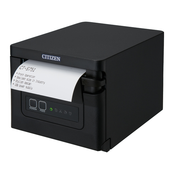
2. EXPLANATION OF PRINTER PARTS 2.1 Printer Appearance Names of parts 1. Paper cover Open to load paper. Also open to clear a cutter error. * The paper cover cannot be used for manual cutting. Refer to 4.2 Clearing a Cutter Error 2. - Page 18 Operation panel The operation panel has five LEDs and two buttons. LED name Color Description POWER LED Green Lights when the power is on, turns off when the power is off. Lights or flashes when no paper or low paper is detected. PAPER LED Green May also light or flash when other abnormalities are detected.
-
Page 19: Inside The Paper Cover
2.2 Inside the Paper Cover 2, 3 1. Print head (thermal) Prints characters and graphic data on paper (paper rolls). 2. Paper near-end (PNE) sensor Detects when the paper is near the end of the roll. Adjust the position of the sensor to determine when it detects the end of the paper is near. -
Page 20: Other Built-In Functions
2.3 Other Built-in Functions Buzzer Buzzes when errors occur or when operations or command operations are performed. Refer to 4.5 Error Indications User memory You can save user-defined logo and character data in this memory. Data remains stored in this memory even if the printer is turned off. For information on how to save data, refer to the Command Reference. - Page 21 Paper saving functions Memory switches MSW8-3 through MSW8-4 can be used to configure the settings below, which save paper. Ÿ Top margin suppression The printer back feeds the paper before printing which reduces the blank space at the top edge of the paper. The back feed amount can be specified.
-
Page 22: Setup
3. SETUP 3.1 Connecting the AC Power Cord Turn off the power. Connect the power connector to the AC adapter cable connector. Next, connect the AC power cord to the AC inlet, and insert the plug into an electric outlet. 1. -
Page 23: Serial Interface Board
3.2 Serial Interface Board Data can be exchanged by serial communication. Connecting the Interface Cable Turn off the power. Confirm the orientation of the interface cable and connect it to the port. Insert the other connector firmly into the interface port of the host computer. CAUTION ... -
Page 24: Usb Interface
3.3 USB Interface Data can be exchanged by USB communication. Specifications Standard USB 2.0 specification-compliant Communication speed Supports 12 Mbps (Full-Speed) transfer Connecting the Interface Cable Turn off the power. Confirm the orientation of the interface cable and connect it to the port. Insert the other connector firmly into the interface port of the host computer. -
Page 25: Bluetooth Interface Board
3.4 Bluetooth Interface Board Names of parts Status LED The Bluetooth communication/connection/error status is indicated by this LED. USB connector Data can be exchanged by USB communication. CAUTION When using this interface board as a USB interface, do not connect USB cables to both the main unit side and interface board side. - Page 26 1. Detecting Bluetooth devices Confirm that Bluetooth is enabled on the host PC before searching for Bluetooth devices. This product will show up as "CT-S751_XX"(XX is last 2 digits of unique BD address.) when it is detected. Select this product from among the detected devices. Note: You can search for devices and change the names.
- Page 27 CAUTION This function is enabled when shipped from the factory. (MSW13-6) Auto reconnection can take some time to connect when the host is not an iOS device. Even if the partner device is an iOS device, the conditions below can interfere with the auto reconnection function.
-
Page 28: Bluetooth Usb Host Interface Board
3.5 Bluetooth USB host interface board In addition to printer control via Bluetooth communication, Bluetooth USB host inter- faces can control peripheral devices connected via a USB port. Connecting a Peripheral Device Turn off the power. Connect the cable of a peripheral device to this port. CAUTION A peripheral device cannot be controlled if it is connected to the USB power supply port. - Page 29 Connecting a USB Device The function assigned to each USB port differs. Connect the USB device to be connected to the correct place in reference to the fol- lowing figure. For peripheral device control Connect a peripheral device. The connected peripheral device can be controlled. For host computer communication Connect with a host computer.
- Page 30 Names of parts Panel button Control this interface board. USB 2 port Connect a peripheral device. CAUTION Only connect peripheral devices specified by our company to the USB port. Only plug in/remove peripheral devices when the printer power is turned off. Pairing operation You need to perform the operations below the first time you establish a Bluetooth con- nection for Bluetooth data communication.
- Page 31 2. Configuring pairing settings Normally, selecting the printer during device detection will transition directly to pairing settings. CAUTION Some host PC configurations and models may not transition directly to pairing settings after the printer is selected during device detection. The operation required to configure pairing settings depends on whether SSP (secure simple pairing) is enabled on the host PC.
- Page 32 Enabling and disabling auto reconnect During self test, press the FEED button 3 times -> Auto reconnect = Valid During self test, press the FEED button 4 times -> Auto reconnect = Invalid At the end of self test, new setting will be printed as Auto reconnect [Valid] or [Invalid]. Refer to 4.3 Self Test Panel button operation Use the panel button on the rear of the Bluetooth board to operate this board.
- Page 33 Print the interface board state After starting the printer, pressing the panel button once prints the interface board state. Print example 1. Board firmware version 2. Address of equipped Bluetooth module 3. Bluetooth name 4. Response profile in Bluetooth transmission 5.
-
Page 34: Ethernet (Lan)/Wireless Lan Interface Board
3.6 Ethernet (LAN)/Wireless LAN Interface Board This section provides an overview of the interface board. For details on this board, in- cluding explanations about the USB host function and XML peripheral device support, refer to the separate manual. Connecting the Interface Cable Turn off the power. - Page 35 Connecting a Peripheral Device Turn off the power. Connect the cable of a peripheral device to this port. CAUTION A peripheral device cannot be controlled if it is connected to the USB power supply port. Be sure to connect it to the USB port of the interface board. Connecting a USB Device The function assigned to each USB port differs.
- Page 36 For supplying power Connect a mobile device or other USB device. Power can be supplied to a connected USB device. * This port does not support USB data communication. Refer to 3.8 USB Power Supply Port For wireless LAN adapter connection Connect a wireless LAN adapter.
- Page 37 LED Functions The tables below explain how to interpret LED indications. Ethernet Wireless LAN Ethernet USB host model 1. Wired LAN transmission speed Transmission speed LED (green) 100 Mbps 10 Mbps/Not connected Unlit 2. Wired LAN connection/transmission status Connection status LED (yellow) Connected Not connected...
- Page 38 Web Manager The interface board has a Web Manager function that can be used to connect to the board with a web browser and change board settings. Starting up Web Manager Start up a web browser. In the address field, input the board's IP address and then press [Enter]. HOME Screen This is the Web manager home screen.
- Page 39 CONFIG Screen This will display the Login dialog box shown below. Log in as an administrator and then configure interface board settings. User Name Input a board administrator user name. (Initial setting: admin) Password Input the administrator user password. (Initial setting: admin) ...
-
Page 40: Lightning Usb Host Interface Board
3.7 Lightning USB host interface board In addition to printer control via USB (Lightning) communication, Lightning USB host interfaces can control peripheral devices connected via a USB port. Connecting the Interface Cable Turn off the power. Confirm the orientation of the interface cable and connect it to the port. Connect the other connector to the interface connector of an Apple device. - Page 41 Connecting a Peripheral Device Turn off the power. Connect the cable of a peripheral device to this port. CAUTION A peripheral device cannot be controlled if it is connected to the USB power supply port. Be sure to connect it to the USB port of the interface board. —...
- Page 42 Connecting a USB Device For peripheral device control Connect a peripheral device. The connected peripheral device can be controlled. For Apple device connection Connect with an Apple device. The printer and Apple device will communicate via the Lightning cable. Fast charging of the Apple device can also be carried out. For host computer communication Connect with a host computer.
- Page 43 Names of parts Panel button Control this interface board. USB port for peripheral device connection (3 ports) Connect a peripheral device. USB port for Apple device connection (1 port) Connect an Apple device. Data can be transmitted even during fast charging of Apple devices. Green LED This LED indicates the communication status with the printer.
- Page 44 Panel button operation Use the panel button on the rear of the Lightning board to operate this board. 1. Print the interface board state After starting the printer, pressing the panel button once prints the interface board state. 1. System information of this interface board 2.
- Page 45 LED Functions The tables below explain how to interpret LED indications. 1. Communication status with the printer Communicating LED (green) Not connected Unlit Connected Communication in Flashing progress 2. Connection status with an Apple device Communicating LED (red) Not connected Unlit Connected Communication failed...
-
Page 46: Usb Power Supply Port
3.8 USB Power Supply Port Power (max. 2.1 A) can be supplied to a mobile device or other USB device by con- necting the cable of the USB device to the power supply port. Connecting Mobile Device or Other Device Turn off the power. - Page 47 For supplying power Connect a mobile device or other USB device. Power can be supplied to a connected USB device. * This port does not support USB data communication. Refer to 3.8 USB Power Supply Port CAUTION This port does not support USB data communication. ...
-
Page 48: Connecting The Cash Drawer
3.9 Connecting the Cash Drawer Turn off the power. Confirm the orientation of the cash drawer kick-out cable connector and connect it to the cash drawer kick-out connector at the back of the printer. Remove the screw for the ground wire. Screw the cash drawer’s ground wire to the body of the printer. - Page 49 (2) Electric characteristics 1) Drive voltage: 24 VDC 2) Drive current: Approx. 1 A max. (not to exceed 510 ms.) 3) DRSW signal: Signal levels: “L” = 0 to 0.5 V, “H” = 3 to 5 V (3) DRSW signal Status can be tested by commands.
-
Page 50: Precautions For Installing The Printer
3.10 Precautions for Installing the Printer This printer can only be positioned horizontally. It cannot be positioned vertically or on a wall. Horizontal position Vertical position CAUTION Do not use the printer under the following conditions. Avoid locations subject to vibration or instability. ... -
Page 51: Adjusting The Paper Near-End Sensor
3.11 Adjusting the Paper Near-end Sensor Change the settings of the paper near-end sensor to set the position at which the near- end of the paper is detected. Gently press the paper near-end sensor with your finger. Keep the paper near-end sensor pressed as you move it left and right. The sensor posi- tions are shown below for the various diameters of the paper roll used. -
Page 52: Loading Paper
3.12 Loading Paper Turn on the power. Push down the cover open lever to open the paper cover. CAUTION When pushing down on the lever, take care that you do not pinch your fingers in the gap below the bottom of the lever. Load the paper roll so that the printable side of the paper is facing up, as shown by arrow A. - Page 53 CAUTION When opening the paper cover, be careful not to touch the entrance of the blade of the auto cutter. The print head is very hot immediately after printing. Be careful not to touch it with your hands. ...
-
Page 54: 58-Mm Width Roll Paper Partition
3.13 58-mm Width Roll Paper Partition Turn off the power. Push down the cover open lever to open the paper cover. Mount the supplied partition to the groove. When using the 80-mm width roll paper, remove the partition. Change the print area width while referring to “Manual Setting of Memory Switches” in Section 5.3. -
Page 55: Mounting The Cable Cover
3.14 Mounting the Cable Cover Align the claws of the cable cover with the grooves in the printer main unit and then insert them. 1. Cable cover — —... -
Page 56: Precautions For Creating Applications And Practical Operations
If this is the case, try using a cable with ferrite cores on both ends, which are very ef- fective at eliminating EMI. 3.16 Download Site for Various Electronic Files You can view support information and download the latest documents, drivers, utilities, etc. from the following site. http://www.citizen-systems.co.jp/en/printer/download/ — —... -
Page 57: Maintenance And Troubleshooting
4. MAINTENANCE AND TROUBLESHOOTING 4.1 Periodic Cleaning A dirty print head or platen may reduce printing quality or cause malfunctions. We rec- ommend cleaning the printer periodically (every 2 to 3 months) as shown below. Turn off the power. Push down the cover open lever to open the paper cover. Wait a few minutes until the print head cools. -
Page 58: Clearing A Cutter Error
4.2 Clearing a Cutter Error If the auto cutter stops during the auto cutter operation with the blade of the auto cutter in the open position due to foreign matter entering, paper jamming, etc., the CUTTER LED flashes. When a cutter error occurs, resolve the cutter error with the following procedure. -
Page 59: Self Test
4.3 Self Test You can use self test to check for printer problems. Performing a self test operation While paper is loaded, press and hold the FEED button and turn on the power. Hold the FEED button down for about one second until the buzzer sounds. Release the button to start self test. -
Page 60: Hexadecimal Dump Printing
4.4 Hexadecimal Dump Printing Print received data in hexadecimal. If problems such as missing or duplicated data occur, this function allows you to check whether or not the printer is receiving data cor- rectly. How to do hexadecimal dump printing Load paper. -
Page 61: Error Indications
4.5 Error Indications Paper end, paper near-end The end of the roll of paper is detected at two stages, paper near-end and paperend. When paper near-end is detected, the PAPER LED flashes. Prepare a new paper roll. When paper end is detected, the PAPER LED lights and the buzzer sounds. Load a new paper roll. - Page 62 The status display for various messages is shown below. Status PAPER LED CUTTER LED COVER LED SERVICE LED Buzzer*1 Paper near-end Unlit Unlit Unlit Paper-end Unlit Unlit Unlit Yes*2 Cover open*3 Unlit Unlit Unlit Yes*2 Cover open II*4 Unlit Unlit Unlit Yes*2 Cutter locked...
-
Page 63: Paper Jams
4.6 Paper Jams Take care to avoid obstruction of the paper outlet and paper jamming around the outlet during printing. If paper cannot get out of the printer, it can roll up on the platen inside the printer and cause an error. If the paper wraps around the platen, open the paper cover and carefully pull the paper out. -
Page 64: Other
5. OTHER 5.1 External Views and Dimensions (Unit: mm) — —... -
Page 65: Printing Paper
5.2 Printing Paper Use the paper shown in the following table or paper of the same quality. Paper type Product name Recommended Nippon Paper TP50KR-2Y, TP50KJ-R, TL69KS-LH thermal roll paper Oji Paper PD150R, PD160R, PD160R-63 Mitsubishi Paper Mills HP220AB-1, P220AB Koehler KT48-FA (Unit: mm) (Unit: mm) -
Page 66: Manual Setting Of Memory Switches
Press the FEED button three and close the paper cover. The printer enters memory switch quick setting mode. The selectable item “Model” and the selection are printed. Model ( CITIZEN CT-S310 ) Selection Selectable item Press the FEED button. A selection is printed in order through the cycle each time the FEED button is pressed. - Page 67 Manufacturer Full Col CBM1000 Character width space Print Width Print Mode Space 58 mm WaitData Invalid 384 dots CITIZEN CT-S310 80 mm WaitData Invalid 576 dots 0 dot WaitData Invalid 360 dots 0 dot 58 mm 1 dot WaitData Invalid...
- Page 68 Individual setting mode Set the memory switches individually. Do the settings while confirming the memory switch function and settings on the print- out. Load paper. While the paper cover is open, press and hold the FEED button and turn on the power. Press the FEED button twice and close the paper cover.
- Page 69 Repeat steps 5 to 7 to change different functions for the current memory switch num- ber. Open the paper cover and close it. The changed memory switch settings are printed. 10. Repeat steps 4 to 9 to change functions for a different memory switch number. 11.
- Page 70 The function of each memory switch is shown in the following table. (Shaded values are factory settings.) Switch no. Function MSW1-1 Power ON Info Valid Not Send MSW1-2 Buffer Size 4K bytes 45 bytes MSW1-3 Busy Condition Full/Err Full MSW1-4 Receive Error Print“?”...
- Page 71 Switch no. Function MSW5-1 Buzzer Valid Invalid MSW5-2 Line Pitch 1/360 1/406 MSW5-3 USB Mode Virtual COM Printer Class MSW5-4 Reserved Fixed — MSW5-5 Reserved Fixed — MSW5-6 Reserved Fixed — MSW5-7 Reserved Fixed — MSW5-8 Reserved Fixed — MSW6-1 Act.
- Page 72 Switch no. Function Initial setting Setting value MSW9-1 Code Page PC437 PC 437, Katakana, PC 850, PC 858, PC 860, PC 863, PC 865, PC 852, PC 866, PC 857, WPC1252, Space page, PC 864, ThaiCode11 1Pass, ThaiCode11 3Pass, ThaiCode18 1Pass, ThaiCode18 3Pass, TCVN-3, WPC1258 MSW9-2 Int’Char Set...
- Page 73 CT-S751_UM_110_EN PMC-2008 August 2020...