Table of Contents
Advertisement
Available languages
Available languages
Quick Links
Page 1 of 23
LP0300BK
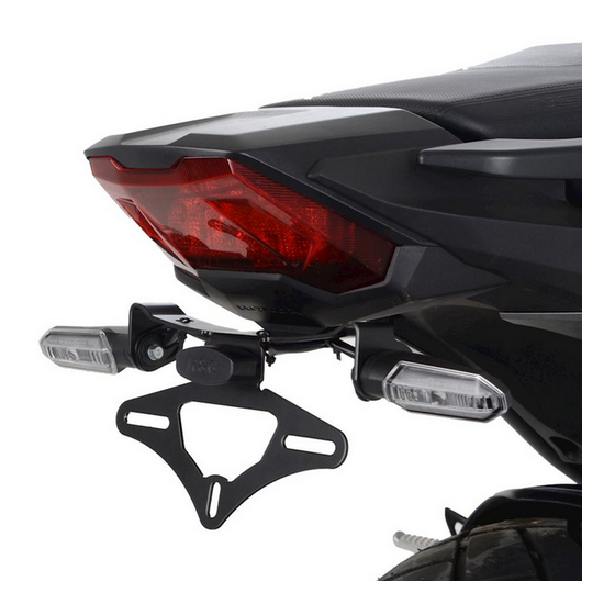
FITTING INSTRUCTIONS FOR LP0300BK LICENCE PLATE BRACKET
FOR HONDA CB650R & CBR650R 2021
FOR ORIGINAL AND AFTERMARKET M8 INDICATORS
T
.
HIS KIT CONTAINS THE ITEMS PICTURED AND LABELLED OVER PAGE
S
.
OME PARTS MAY BE SHOWN FOR CLARITY OF INSTRUCTIONS ONLY
D
.
O NOT PROCEED UNTIL YOU ARE SURE ALL PARTS ARE PRESENT
P
.
LEASE READ ALL INSTRUCTIONS BEFORE PROCEEDING
IF IN ANY DOUBT WHEN FITTING OUR PRODUCTS, CONSULT ONE OF OUR DEALERS
OR HAVE FITTED BY A QUALIFIED TECHNICIAN.
P
LEASE NOTE THAT THE WAY THE KIT IS PACKED DOES NOT NECESSARILY REPRESENT THE WAY OF
.
MOUNTING TO THE BIKE
I
,
N THE EVENT OF RUBBER WASHERS BEING USED TO HOLD COMPONENTS ONTO BOLTS
.
THESE RUBBER WASHERS CAN BE THROWN AWAY
DIGITAL COPIES OF THESE INSTRUCTIONS ARE AVAILABLE FROM:
WWW.RG-RACING.COM
R&G
Unit 1, Shelley's Lane, East Worldham, Alton, Hampshire, GU34 3AQ
Tel: +44 (0)1420 89007 Fax: +44 (0)1420 87301
www.rg-racing.com
Email:
info@rg-racing.com
Advertisement
Table of Contents

Related Manuals for R&G LP0300BK


Summary of Contents for R&G LP0300BK
- Page 1 Page 1 of 23 LP0300BK FITTING INSTRUCTIONS FOR LP0300BK LICENCE PLATE BRACKET FOR HONDA CB650R & CBR650R 2021 FOR ORIGINAL AND AFTERMARKET M8 INDICATORS HIS KIT CONTAINS THE ITEMS PICTURED AND LABELLED OVER PAGE OME PARTS MAY BE SHOWN FOR CLARITY OF INSTRUCTIONS ONLY...
-
Page 2: Tools Required
Page 2 of 23 LP0300BK TOOLS REQUIRED GENERAL TORQUE SETTINGS • M4 BOLT = 8Nm Set of metric Allen keys to include 5mm A/F size. M5 BOLT = • 6, 12 & 13mm spanners or socket and wrench. M6 BOLT = •... - Page 3 Page 3 of 23 LP0300BK Component Diagram PICTURE 1 PICTURE 2 R&G Unit 1, Shelley’s Lane, East Worldham, Alton, Hampshire, GU34 3AQ Tel: +44 (0)1420 89007 Fax: +44 (0)1420 87301 www.rg-racing.com Email: info@rg-racing.com...
- Page 4 Page 4 of 23 LP0300BK PICTURE 3 PICTURE 4 PICTURE 5 PICTURE 6 PICTURE 7 PICTURE 8 R&G Unit 1, Shelley’s Lane, East Worldham, Alton, Hampshire, GU34 3AQ Tel: +44 (0)1420 89007 Fax: +44 (0)1420 87301 www.rg-racing.com Email: info@rg-racing.com...
- Page 5 Page 5 of 23 LP0300BK PICTURE 9 PICTURE 10 PICTURE 11 PICTURE 12 PICTURE 13 PICTURE 14 R&G Unit 1, Shelley’s Lane, East Worldham, Alton, Hampshire, GU34 3AQ Tel: +44 (0)1420 89007 Fax: +44 (0)1420 87301 www.rg-racing.com Email: info@rg-racing.com...
- Page 6 Page 6 of 23 LP0300BK PICTURE 15 PICTURE 16 PICTURE 17 PICTURE 18 PICTURE 19 PICTURE 20 R&G Unit 1, Shelley’s Lane, East Worldham, Alton, Hampshire, GU34 3AQ Tel: +44 (0)1420 89007 Fax: +44 (0)1420 87301 www.rg-racing.com Email: info@rg-racing.com...
- Page 7 Page 7 of 23 LP0300BK PICTURE 21 PICTURE 22 PICTURE 23 PICTURE 24 PICTURE 25 PICTURE 26 R&G Unit 1, Shelley’s Lane, East Worldham, Alton, Hampshire, GU34 3AQ Tel: +44 (0)1420 89007 Fax: +44 (0)1420 87301 www.rg-racing.com Email: info@rg-racing.com...
-
Page 8: Fitting Instructions
Page 8 of 23 LP0300BK PICTURE 27 PICTURE 28 PICTURE 29 PICTURE 30 FITTING INSTRUCTIONS • Remove the pillion seat, using the lock under the tail for the passenger seat (arrowed in picture 1). Then using a 5mm Allen key, remove the 2 rider seat bolts as shown in picture 2. - Page 9 Page 9 of 23 LP0300BK If using OEM indicators: If you are re-using the original indicators these will need to be removed from the original licence plate unit following the steps here, if using Mini indicators, skip this section. •...
- Page 10 Page 10 of 23 LP0300BK • If using RGR0002 Resistors they should be connected at this point using the colour chart below: Yellow – Yellow Black – Black Licence plate illuminator • Once indicators are fitted, the licence plate illuminator (item 2) can be assembled and fitted to the Tail bracket (item 1) •...
- Page 11 Page 11 of 23 LP0300BK ISSUE 1 18/01/2021 (NSY) CONSUMER NOTICE The catalogue description and any exhibition of samples are only broad indications of the Products and R&G may make design changes which do not diminish their performance or visual appeal and supplying them in such state shall conform to the order.
- Page 12 Page 12 of 23 LP0300BK NOTICE DE MONTAGE POUR LP0300BK SUPPORT DE PLAQUE POUR HONDA CB650R & CBR650R 2021 CLIGNOTANTS D’ORIGINE ET NON D’ORIGINE M8 E KIT CONTIENT LES ARTICLES ILLUSTRES ET ETIQUETES SUR LA PAGE ERTAINES PARTIES PEUVENT ETRE PRESENTES UNIQUEMENT POUR LA CLARTE DES INSTRUCTIONS...
-
Page 13: Outils Requis
Page 13 of 23 LP0300BK OUTILS REQUIS VALEURS DE SERRAGE • M4 BOULON = 8Nm Clés Allen 5mm M5 BOULON = • Clé à cliquet + douilles 6, 12 & 13mm. M6 BOULON = • Tournevis cruciforme. M8 BOULON = 20Nm •... -
Page 14: Notice De Montage
Page 14 of 23 LP0300BK NOTICE DE MONTAGE • Retirez le siège passager en utilisant le verrou sous le support du siège passager (flèche sur la photo 1). Puis à l'aide d'une clé Allen de 5 mm, retirez les 2 boulons du siege du pilote comme indiqué... - Page 15 Page 15 of 23 LP0300BK • Retirez les quatre boulons fléchés sur les photos 13 et 8, puis abaissez-les soigneusement loin de la moto tout en faisant passer les 3 fils déconnectés à travers les ouvertures en plastique de l'unité arrière en prenant note du chemin de câblage.
- Page 16 Page 16 of 23 LP0300BK • Enfilez un couvercle de câblage de clignotant (article 8) sur chaque paire de fils de clignotant (une petite quantité de lubrifiant ou de liquide vaisselle vous aidera) comme indiqué sur la photo 27. •...
- Page 17 Page 17 of 23 LP0300BK • Utilisez les serre-câbles (article 10) et les clips autocollants (article 12) pour fixer les fils de clignotant et de feu et assurez-vous qu'ils soient propres et cachés de la vue. • Rangez le câblage à l'intérieur de la moto à l'aide du serre-câble d’origine, assurez-vous que les fils n'interfèrent pas avec les supports de siège.
- Page 18 Page 18 of 23 LP0300BK MONTAGEANLEITUNG FÜR LP0300BK KENNZEICHENHALTER FÜR HONDA CB650R & CBR650R 2021 FÜR ORIGINALBLINKER & M8-BLINKER AUS DEM ZUBEHÖRMARKT EILE SIND UNTEN ABGEBILDET UND GEKENNZEICHNET IE ABGEBILDETEN EILE DIENEN LEDIGLICH ZUR RKLÄRUNG Ü BERPRÜFEN IE ZUERST DASS ALLE...
-
Page 19: Sie Benötigen Folgendes Werkzeug
Page 19 of 23 LP0300BK SIE BENÖTIGEN FOLGENDES WERKZEUG ALLGEM ANZUGSDREHMOMENT • M4 SCHRAUBE = 8Nm Satz Inbusschlüssel inkl. Gr. 5mm A/F M5 SCHRAUBE = • 6, 12 & 13mm Schraubenschlüssel oder Steckschlüssel M6 SCHRAUBE = M8 SCHRAUBE = 20Nm •... - Page 20 Page 20 of 23 LP0300BK MONTAGEANLEITUNG • Entfernen Sie den Beifahrersitz - das Schloss ist am Heck unter dem Beifahrersitz (siehe Abbildung 1). Danach Die zwei Schrauben am Fahrersitz mit einem 5mm Inbusschlüssel entfernen – siehe Abbildung 2. • Die original Verbindungen für die Blinker und die Kennzeichenbeleuchtung unter dem Sitz orten.
- Page 21 Page 21 of 23 LP0300BK • Entfernen Sie die vier Schrauben, die in Abbildungen 13 und 8 abgebildet sind, dann den original Kennzeichenhalter vom Motorrad herabsetzen und die 3 abgetrennten Kabel vorsichtig durch die Öffnungen am Heck führen. Notieren Sie die Verlegung der Kabel.
- Page 22 Page 22 of 23 LP0300BK abgebildet. Mit der Sicherungsmutter, die im Lieferumfang des Blinkers enthalten ist befestigen. NICHT ÜBERZIEHEN. • Jeweils eine Blinker-Abdeckung (Artikel 8) über jedes Kabelpaar führen (eine kleine Menge Spülmittel kann hierbei helfen) wie in Abbildung 27 abgebildet.
- Page 23 Page 23 of 23 LP0300BK • Es empfiehlt sich, zu diesem Zeitpunkt die Zündung einzuschalten und die ordnungsgemäße Funktion der kompletten Beleuchtung zu überprüfen. Falls die Beleuchtung nicht funktionieren sollte, tauschen Sie die Kabelverbinder untereinander. • Die Kabelbinder (Artikel 10) und die selbstklebenden Kabelclips (Artikel 12) benutzen, um die Kabel für die Blinker und die Beleuchtung zu befestigen und ordentlich zu verstauen.