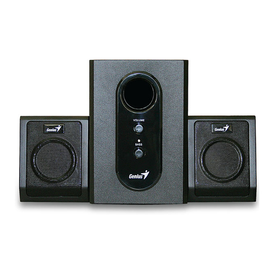
Summary of Contents for Genius SW-2.1 355
- Page 1 S S e e rvi rvice G ce Gui uide SW-2.1 355 SW-2.1 355 SERVICE VICE GUIDE GUIDE K K EY SYSTEM CO EY SYSTEM CORP Version Version 1.0 Page Page 1 1 of of 20...
-
Page 2: Revis Io N Histo Ry
S S e e rvi rvice G ce Gui uide SW-2.1 355 SW-2.1 355 R R e e visi vision on H H isto istory ry Version Version Date Date Change Change 15/11/2007 15/11/2007 Version Version 1.0 Page Page 2 2 of of 20... -
Page 3: Table Of Contents
Service Guide SW-2.1 355 Table of Contents Revis io n Histo ry………………………………………………………………….2 Tabl e of cont ents……………………………………………………………...…3 Getti ng Start …………………………………………………….………………...4 Conventions Used in this Guide…………………………………………….…4 Safety Precautions……………………………………………………………… Chapter 1. How t o Handle Defecti ve Retur ns ……………………………….5 1.2 Problem ………………………………………………………………………6... -
Page 4: Getti Ng Start
Service Guide SW-2.1 355 Getting Started Conventions Used in the Guide Pay Special Attention: Instructions that are important to remember and may prevent mistakes. Caution: Information that, if not followed, may result in damage to the product. Safety Precautions The following precautions should be observed in handing the speaker described in this guide: Place the speakers on a flat, level and stable surface. -
Page 5: Chapter 1. How To Handle Defective Return S
Service Guide SW-2.1 355 Chapter 1. How to Handle Defective Return s 1.1 Overvi ew Receiving Defective speaker from customers Verifying problems Proceeding Necessary tests Function NG Function OK Function NG Analyzing possible Malfunction cause Deciding & proceeding the Rectification methods... -
Page 6: Problem
Service Guide SW-2.1 355 1.2 Problems Item Probl em Descrip tion , ( ) 1.2.1 No power indicator no light 1.2.2 No sound 1.2.3 Right channel no sound 1.2.4 Left channel no sound 1.2.5 Woofer no sound 1.2.6 Noise 1.2.7 LED indicators no light Version 1.0... -
Page 7: No Power , Led ( Indicator ) Unlighted
Service Guide SW-2.1 355 *Attention Please follow the numbered sequence marked within parenthesis given in individual Flow chat in that this is the best-recommended sequence to rectify the problems. 1.2.1 No power indicator unlighted , ( ) No power indicator ... -
Page 8: No Sound
Service Guide SW-2.1 355 1.2.2 no sound No sound Problem 8P assembled line Defective Input cable defectively short-circuited, dry components damaged or connected between soldered or of VR1, JK1, Analyze and defective CON1 and CON2 damaged U1, U2, identify the... -
Page 9: Right Channel No Sound
Service Guide SW-2.1 355 1.2.3 Right channel no sou nd Right channel no sound Problem Input cable Right Speaker PCB damaged, 1. Defective JK1, JK2 damaged or cable damaged or dry-soldered or Defective assembled line defective defective short-circuited between CON1 and CON2 Analyze and... -
Page 10: Left Channel No Sound
Service Guide SW-2.1 355 1.2.4 Left chann el no so und Problem Left channel no sound Left Speaker cable damaged, Input cable 1. Defective JK1, JK2 damaged or dry-soldered or damaged or Defective assembled line Analyze and defective short-circuited defective... -
Page 11: Woofer No Sound
Service Guide SW-2.1 355 1.2.5 Woofer no sou nd Problem Woofer no sound Defective assembled line between Woofer driver unit Analyze and CON1 and CON2 dry-soldered or identify the , , , , , R14VR2 R15, defective causes , ,... -
Page 12: Noise
Service Guide SW-2.1 355 1.2.6. Noise Problem Noise , 1. D1-D4 C29 dry-soldered Vibration from too Driver units or defective long lead wire of damaged Analyze and driver units identify the components around causes dry-soldered or defective 3. PCB broken or dry-soldered... -
Page 13: Led Indicators No Light
Service Guide SW-2.1 355 1.2.7. LED indicators no l igh t Problem LED indicators no light 1. Defective, dry-soldered, or broken PCB Analyze and 2. R18 , LED defective or dry-soldered identify the causes Check and replace Solutions Version 1.0... -
Page 14: Chapt Er 2. Speci Fi Cation
Service Guide SW-2.1 355 Chapter 2. Specifications Satellite DESCRIPTION NO UNIT NOMINAL LIMIT @ THD 10% ≥ 2.3 RATED OUTPUT POWER SENSITIVITY ( 1KHz )@ RATED O/P POEWR 440±44 SENSITIVITY ( 1KHz )@ 1W O/P POWER 200±20 MAX INPUT LEVEL @ 1% THD 230±23... -
Page 15: Chapter 3 Bloc K Diagram
Service Guide SW-2.1 355 Chapter 3 Bloc k diagram Version 1.0 Page 15 of 20... -
Page 16: Chapter 4 Exploded View
Service Guide SW-2.1 355 Chapter 4 Exploded view Subwoofer Version 1.0 Page 16 of 20... -
Page 17: Satellite
Service Guide SW-2.1 355 Chapter 4 Explod ed view Satellite Version 1.0 Page 17 of 20... -
Page 18: Woofer
Service Guide SW-2.1 355 Cha ter 5 Part list Woofer Ref. NO Description Part NO. Knob EP40711156 Woofer front panel EP40910362 Woofer foot mat, 8*3MM EP73050003 wood cabinet EP53355J01 volume switch, 16KG-B50K-L15 EP1B010070 Paper tube EP41590051 woofer unit , 4” 4ohms 10W EP16050049 Transformer;... -
Page 19: Chapter 6 Important Notes
Service Guide SW-2.1 355 Cha ter 6. Im ortant Notes 6.1 Packing requirement for sending the PCB assembly by post PCB assembly is a kind of sophisticated electronic circuit board. Well packing will be required when sending them by post. -
Page 20: Chapter 7 Schematic Diagram
Service Guide SW-2.1 355 Cha ter 7. Schematic dia ram Version 1.0 Page 20 of 20...


