
Related Manuals for Viessmann ESS VITOBLOC 200


Summary of Contents for Viessmann ESS VITOBLOC 200
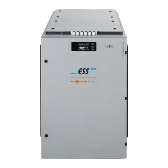
- Page 1 Operating instructions for contractors VITOBLOC 200 Type EM-20/39 Part no. 7519058 CHP unit for operation with natural gas Please retain 5783 171-1 GB 03/2014...
- Page 2 Imprint This appliance meets all basic requirements of the applicable standards and guidelines. Conformity has been verified. All associated documents and the original Declaration of Conformity are available from the manufacturer. NOTE The Vitobloc 200 CHP unit is not suitable for 60 Hz operation.
-
Page 3: Table Of Contents
Table of contents Introduction ..................4 Structure of the safety instructions ................4 Depiction of safety instructions ................... 4 Safety signs ........................5 Trademarks ........................5 Intended use ..................6 Safety ....................7 Legal disclaimer ......................7 Safety equipment ......................7 Personnel ........................ -
Page 4: Introduction
Introduction Introduction content its own. This declaration applies to all external This document applies to the Vitobloc 200 EM-20/39 links and references to the internet specified within combined heat and power (CHP) unit - also referred this document. to hereinafter as the "machine". This document must always be stored within easy reach of the system. -
Page 5: Safety Signs
Introduction Safety signs The following signs (safety signs) are attached to the machine or must be affixed on/in the plant room by the operator: 1.3.1 Prohibition signs 1.3.2 Warning signs Access for unauthorised persons Warning of dangerous electrical forbidden! voltage! Areas identified in this way may only Means "stop"... -
Page 6: Intended Use
Intended use Intended use Incorrect use The operator of the Vitobloc 200 EM-20/39 CHP unit must observe country-specific legislation and All applications deviating from the intended use are regulations. deemed to be impermissible incorrect use. This Target group includes: ● This document is intended solely for use by Application areas not listed under "Application". -
Page 7: Safety
Safety Safety Legal disclaimer Safety equipment The CHP unit is built in accordance with the latest The installer protects the CHP unit from unauthorised engineering standards and recognised safety access by installing it in a locked plant room. The regulations. Nevertheless, impermissible use can still installer is also responsible for ensuring that all safety result in risk to life and limb or to machine impairment equipment is fully installed and fully functional. -
Page 8: Personnel
Safety Personnel All personnel working on the CHP unit must be trained in its use. They must also have read and The installer is responsible for the following tasks: understood the documentation, including the chapter ● Installing the CHP unit. concerning safety. -
Page 9: General Safety Regulations
Safety General safety regulations The CHP unit may only be used in technically flawless ● In the event of any functional faults, shut down the condition, in accordance with its intended application machine and make it safe. Correct all faults and with awareness of all safety-relevant factors. -
Page 10: Special Safety Regulations
Safety Special safety regulations ● 3.5.1 Siting and storage Installation of the machine and its peripheral connection systems may only be carried out by authorised personnel from a specialist company, ATTENTION who have been instructed in these tasks by the manufacturer. -
Page 11: Information Regarding Particular Types Of Hazard
Safety Information regarding particular types of hazard 3.6.1 Thermal hazards 3.6.2 Radiation WARNING DANGER In the event of a fault, safety pressure The generator's electromagnetic fields limiters can be triggered and discharge can cause faults in active implants hot coolant. (e.g. - Page 12 Safety 3.6.4 Hazards during transportation 3.6.5 Electrical energy/equipment DANGER DANGER Suspended loads. Live components! Falling loads can cause death or Death by electrocution on contact serious injury ► Only trained, authorised, specialist ► Never stand under suspended personnel may perform work on the loads.
- Page 13 Safety 3.6.6 Gas, dust, steam, smoke WARNING Dust and dirt. Restricted visibility ► Cover machine adequately. ► Close or cover control panels. ► Wear personal protective equipment (e.g. protective gloves, safety goggles) during welding and grinding/polishing work. 3.6.7 Oils, greases and other chemical substances WARNING Take care when handling oils, greases...
-
Page 14: Product Description
Product description Product description Overview The Vitobloc 200 EM-20/39 CHP unit consists of the following components assembled on a base frame: ● Gas engine ● Gas supply unit ● Synchronous generator ● Lubricating oil system ● Sealed unvented cooling circuit with heat extraction ●... -
Page 15: Casing
Product description 4.4.2 Display Casing After switching on the machine, the standard screen The casing of the EM-20/39 consists of a frame with appears on the LCD display, showing the current noise attenuating elements for the engine/generator outputs of the EM-20/39. unit. -
Page 16: Type Plate
Product description Type plate The type plate is located on the connection side of the CHP unit. Fig. 7 Vitobloc 200 EM-20/39 type plate Operating instructions VITOBLOC 200 EM-20/39 ESS Energie Systeme & Service GmbH... -
Page 17: Operation
Operation Operation (3) Press the START button ( F ig. 8/2). The EM-20/39 DANGER starts up in automatic mode. Leaks in the exhaust system can cause (4) Operating values are updated and shown on the gas to escape. display. Risk to life due to explosion or poisoning ►... -
Page 18: Optimising Operation
Operation Optimising operation ● Faults and consequential losses resulting from Foil keypad functions prohibited operating conditions are not covered by the warranty or any service contract. ● Always avoid shutting down on full load, as this would subject the components to the highest mechanical loads. - Page 19 Operation 5.3.2 Overview of the control levels Fig. 12 Control levels As the start screen, the standard screen is control level 1. All other control levels are based on the standard screen. The next level is displayed in each case by pressing ...
- Page 20 Operation 5.3.3 Standard screen (level 1) 5.3.4 Menu screen (level 2) After switching on, the control unit standard screen This menu screen represents control level 2 and is displays the current operating status. displayed when the Menu key ( F ig.
- Page 21 Operation 5.3.5 Calling up module parameters (level 3) (1) Select "Modulwerte" (module parameters) in the The following values are shown as an example of operation: menu screen ( F ig. 14). (2) Confirm selection by pressing OK. The module Values Description parameters menu screen opens.
- Page 22 Operation 5.3.6 Calling up info values (level 3) (5) Select the "MinMax" window and confirm by (1) Select "Info" in the menu screen ( F ig. 14). pressing OK. (2) Confirm selection by pressing OK. The "MinMax" menu screen opens (level 4). The "Info"...
- Page 23 Operation Select the "Archiv" (archive) window and confirm by (8) Select the "Wartung" (service) window and pressing OK. confirm by pressing OK. The "Archiv" menu screen opens (level 4). The "Wartung" (service) menu screen opens (level 4). Fig. 19 "Archiv" menu screen Fig.
- Page 24 Operation 5.3.7 Calling up controller values (level 3) (1) Select "Regler" (controller) in the menu screen When the menu screen appears, the "Regler" (controller) window is already marked for F ig. 13). selection. (2) Confirm selection by pressing OK. (3) Confirm "Regler"...
- Page 25 Operation 5.3.8 Calling up enable values (level 3) (1) Select "Freigabe" (enable) in the menu screen The enable settings are displayed in this menu screen. F ig. 13). (2) Confirm selection by pressing OK. After selection, the values can be changed using the arrow keys.
- Page 26 Operation Setting example for continuous operation Daily operation from 08:00 to 18:00: A = 0 00:01 00:01 B = 1 08:00 18:00 C = 0 00:00 00:00 D = 0 00:00 00:00 Setting example for time-differentiated operation Daily operation apart from Tuesday 20:00 to Wednesday 08:00 (legionella pasteurisation) A = 0 00:01...
-
Page 27: Emergency Operation
Operation Emergency operation 5.4.1 EMERGENCY STOP 5.4.2 What to do if gas escapes ● In an emergency, press the EMERGENCY STOP DANGER button on the control panel. Gas is escaping due to a leak in the This shuts down the engine, but the pumps and exhaust system. -
Page 28: Faults And Troubleshooting
Operation 5.4.4 What to do if there may be a leak Faults and troubleshooting In the event of an operational fault, the fault indicator DANGER F ig. 28/1) lights up on the programming and display Leaks in the exhaust system can release field. -
Page 29: Information Regarding Service And Maintenance
Information regarding service and maintenance Information regarding service and maintenance Service and maintenance work must always be carried out by authorised service personnel in accordance with the manufacturer's service list. The service list is maintained as a binding verification document and the original must be retained by the operator. -
Page 30: Shutdown And Decommissioning
Shutdown and decommissioning Shutdown and decommissioning Temporary decommissioning amount of oil in the reservoir in such a way that the oil level is virtually zero by the time of shutdown. In order to maintain any warranty claims, the operator Actions to be taken during shutdown: must protect the EM-20/39 through preservation ●... -
Page 31: Appendix
Appendix 8 Appendix Operating log form The completed forms must be retained. Operating log booklets with forms for 1 year (52 weekly tables) are available from ESS (tel. +49 (0)8191 9279-60) on request. System ID Module - type Serial number System address Tel: Daily checks... - Page 32 Subject to technical modifications. ESS Energie Systeme & Service GmbH Celsiusstrasse 9 D-86899 Landsberg am Lech Telephone: +49 (0)8191 9279-0 Fax: +49 (0)8191 9279-23 info@ess-landsberg.de www.ess-landsberg.de Operating instructions VITOBLOC 200 EM-20/39 ESS Energie Systeme & Service GmbH...