Advertisement
Quick Links
Installation instructions
for contractors
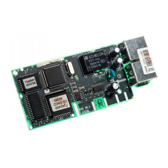
LON communication module
Safety instructions
Please follow these safety instructions closely to prevent accidents
and material losses.
Safety instructions explained
!
Please note
This symbol warns against the
risk of material losses and envi-
ronmental pollution.
Note
Details identified by the word "Note"
contain additional information.
Installation, initial start-up, inspection,
maintenance and repairs must only be
carried out by a competent person
(heating engineer/installation contrac-
tor).
Before working on the equipment/heat-
ing system, isolate the power supply
(e.g. by removing a separate mains
fuse or by means of a mains isolator)
and safeguard against unauthorised
reconnection.
5780 510 GB
8/2017
VIESMANN
When using gas as fuel, also close the
main gas shut-off valve and safeguard
against unauthorised reopening.
Repairing components which fulfil a
safety function can compromise the
safe operation of your heating system.
For replacements, use only original
spare parts supplied or approved by
Viessmann.
Dispose after installation.
Advertisement

Related Manuals for Viessmann 7172173


Summary of Contents for Viessmann 7172173
- Page 1 For replacements, use only original Installation, initial start-up, inspection, spare parts supplied or approved by maintenance and repairs must only be Viessmann. carried out by a competent person (heating engineer/installation contrac- tor). Before working on the equipment/heat- ing system, isolate the power supply (e.g.
- Page 2 Application LON communication module, part number 7172173 7172174 7179113 ■ Boiler with the following ■ Cascade control unit in ■ Oil/gas condensing boiler and heating circuit multi boiler systems: boilers with the fol- control units: – Vitotronic 300-K, lowing weather-com- –...
-
Page 3: Installation
Installation Please note For opening the control units Electronic assemblies can be and position A in the following damaged by electrostatic dis- diagrams, see the correspond- charge. ing installation and service Prior to commencing any work, instructions. touch earthed objects such as heating or water pipes to dis- charge static loads. - Page 4 Installation (cont.) A Main control unit PCB B LON communication module ■ Vitotronic 100, type CC1I ■ Vitotronic 200, type CO1I ■ Vitotronic 300, type CM1I A Main control unit PCB B LON communication module...
- Page 5 Installation (cont.) Vitotronic 200, type KO1B, KO2B Type KO1B is shown A Main control unit PCB B LON communication module Vitotronic 050 and 200-H, type HK1M A Main control unit PCB B LON communication module...
- Page 6 Installation (cont.) Heat pump control units Vitotronic 200, type WO1... A Controller and sensor PCB B LON communication module...
- Page 7 Installation (cont.) WPR300 A Sensor PCB B LON communication module...
- Page 8 Installation (cont.) Vitotronic 200, type HO2B, HO1... A Main PCB B LON communication module...
- Page 9 Installation (cont.) Vitotronic 200, type KW6... A Main PCB B LON communication module...
-
Page 10: Making The Lon Connection
Vitotronic 200, type FO1 and Vitotronic 300, type FW1 A PCB heat distribution control B LON communication module Making the LON connection The Viessmann LON is designed for Observe the requirements for cabling "line" bus topology with a terminator at and operation of the LON interface FTT both ends (accessories). -
Page 11: Connection Versions
Making the LON connection (cont.) Connection versions Connection with LON cable Installation spacing ≤ 7 m A Control unit or communication B LON cable, 7 m long product C Terminator Connection with LON cable and LON coupling Installation spacing 7 to 21 m A Control unit or communication C Terminator product... -
Page 12: Commissioning And Adjustment
F Up to 30 subscribers C Terminator Commissioning and adjustment Service and installation instruc- tions and service instructions for the relevant appliance Viessmann Werke GmbH & Co. KG Viessmann Limited D-35107 Allendorf Hortonwood 30, Telford Telephone: +49 6452 70-0 Shropshire, TF1 7YP, GB...