Advertisement
Quick Links
Advertisement

Related Manuals for LG WB21LMB


Summary of Contents for LG WB21LMB
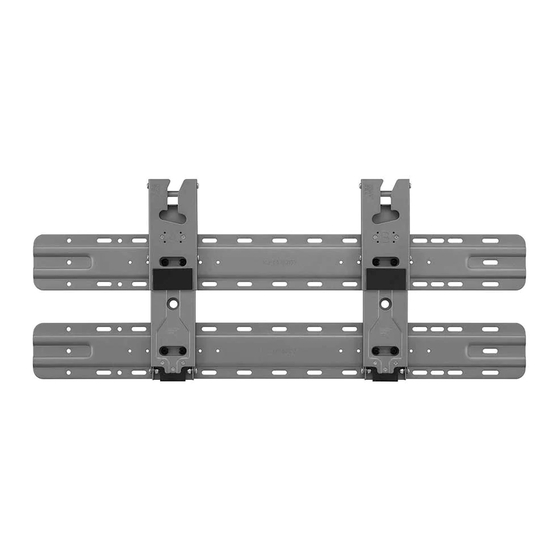
- Page 1 OWNER’S MANUAL Safety and Reference Wall Mount Bracket Please read this manual carefully before operating your set and retain it for future reference. WB21LMB WB21LMC Printed in Korea *MFL71772403* www.lg.com Copyright 2021 LG Electronics Inc. All Rights Reserved. (2106-REV02)
-
Page 2: Precautions For Safety
Accessories 3-2) 39 mm (1.5 inches) (Concrete wall) 2-2) 45 mm (1.7 inches) (Wood stud) TV protection Guide Spacer Wall mount fixing Wall mount fixing cushion B Fixing Screws 2 pcs. anchors 8 pcs. screws 8 pcs. 2 pcs. (M6 x L45) Guide Spacer 2 pcs. - Page 3 Warning Caution Install the product according to the instructions Ask a professional installer appointed by the in the installation manual. store for installation of the product. Failure to install the product according to the Installation by someone other than a professional instructions in the installation manual can result in installer is extremely dangerous and may result in serious personal injury or product damage.
-
Page 4: Before Installation
Unplug the product’s power cord from the wall standards or on the heavily titled wall or ceiling. outlet before installing. LG is not responsible for problems caused by improp- Installing the product while the power cord is er installation of the product, e.g., heavily tilted walls plugged in may result in electric shock or fire. -
Page 5: How To Install
How to install For installation on concrete wall • The appearance of tools may differ from the en- closed images. • Always consult a professional when installing a wall 1. Drill holes in anchor locations with a drill bit of Ø 8 mount. - Page 6 1. Attaching the guide paper to the 2. Install the wall mount support at the location marked on the guide paper. wall - Install after checking the VESA size for the model you purchased. Attach the guide paper to the wall when determining the TV’s installation site.
- Page 7 3. Attaching the TV to the Wall 3. After attaching the TV to the mount on the wall, fasten the screws fixed to the TV to the wall mount. Support Depending on the model, those with horizontal termi- nals are recommended to follow Method 3-2 models without horizontal terminals should follow Method 3-1 and, when installing by Method 3-2, it is recommended to use the side terminal for HDMI...
- Page 8 3-2) Separation distance between TV and 5. Adjust the product’s position by hand so it’s hori- zontal. Hold the left and right bottom sides of the wall: 39 mm (1.5 inches) TV and adjust it to the desired direction. 1. Fasten the enclosed TV guide spacers and guide spacer fixing screws to both sides of VESA.
- Page 9 3. After attaching the TV to the mount on the wall, 5. Adjust the product’s position by hand so it’s hori- fasten the screws fixed to the TV to the wall mount. zontal. Hold the left and right bottom sides of the TV and adjust it to the desired direction.
- Page 10 4. Plugging Additional Cables in 3. Push the TV close to the wall. Be sure to gently push the upper and lower parts of the TV so that While Using the TV the pushing doesn’t affect the TV. Gently push the upper center of the TV once again until it’s com- pletely pressed against the wall.
- Page 11 For installation on wood stud 1. Check the type of wall where the installation will take place. - When installing on a wooden wall, mark the left and right center positions of the wood studs. 2. Assemble by referring to the assembly guide paper which is provided as an accessory. 3.
- Page 12 - When installing on a wooden wall (VESA Size 400) Australia - When installing on a wooden wall (VESA Size 200) - When installing on a wooden wall (VESA Size 300)
- Page 13 - When installing on a wooden wall (VESA Size 400) North America - When installing on a wooden wall (VESA Size 200) - When installing on a wooden wall (VESA Size 300)
- Page 14 - When installing on a wooden wall (VESA Size 400)
- Page 15 1. How to Assemble Support 4. Align the hole in the wall mount support with the hole in the Wall mounting supporter. 1. Place the assembly guide on the box. 2. Align the Wall mounting supporter on the assembly guide paper with the outer line. 5.
- Page 16 Japan 3. Using a Ø 4 mm wood drill bit, drill a hole 76 mm (2.9 inches) or deeper into the screw locations marked on the wall for the wall mount. (Clean the 1. Use the stud finder to locate and mark the center drill holes) of the wall stud.
- Page 17 Australia 3. Using a Ø 4 mm wood drill bit, drill a hole 76 mm (2.9 inches) or deeper into the screw locations 1. Use the stud finder to locate and mark the center marked on the wall for the wall mount. (Clean the of the wall stud.
- Page 18 North America 3. Using a Ø 4 mm wood drill bit, drill a hole 76 mm (2.9 inches) or deeper into the screw locations 1. Use the stud finder to locate and mark the center marked on the wall for the wall mount. (Clean the of the wall stud.
- Page 19 2. Attaching the TV to the Wall 3. After attaching the TV to the mount on the wall, fasten the screws fixed to the TV to the wall mount. Support Depending on the model, models with horizontal ter- minals are recommended to follow Method 2-2 models without horizontal terminals should follow Method 2-1 and, when installing by Method 2-2, it is recommended to use the side terminal for HDMI...
- Page 20 2-2) Separation distance between TV and 5. Adjust the product’s position by hand so it’s hori- zontal. Hold the left and right bottom sides of the wall: 45 mm (1.7 inches) TV and adjust it to the desired direction. 1. Fasten the enclosed TV guide spacers and guide spacer fixing screws to both sides of VESA.
- Page 21 3. After attaching the TV to the mount on the wall, 5. Adjust the product’s position by hand so it’s hori- fasten the screws fixed to the TV to the wall mount. zontal. Hold the left and right bottom sides of the TV and adjust it to the desired direction.
-
Page 22: Specifications
Specifications [Unit: mm (inches)] 73.7 (2.9) 13 (0.5) 9.2˚ 93.3 (3.6) 25 (0.9) Model Name WB21LMB Width 73.7 (2.9) (mm (inches)) Height 285.9 (11.2) (mm (inches)) Depth 13 (0.5) (mm (inches)) Product Weight 0.6 (1.3) x 2 (kg (lbs)) Screws Distance 200/300/400 (mm) (65’’ ) Max. - Page 23 Australia, Japan When not removing the wall mount support [VESA 200] 700 (27.5) 200 (7.8) [VESA 300] 700 (27.5) 300 (11.8)
- Page 24 [VESA 400] 700 (27.5) 400 (15.7) 19 (0.7) 9.2˚ 99.3 (3.9)
- Page 25 North America When not removing the wall mount support [VESA 200] 460 (18.1) 200 (7.8) [VESA 300] 460 (18.1) 300 (11.8)
- Page 26 [VESA 400] 700 (27.5) 400 (15.7) 19 (0.7) 9.2˚ 99.3 (3.9)
- Page 27 [When removing the wall mount support] <North America> [When not removing the wall mount support] Model Name WB21LMB Model Name WB21LMB Width (mm (inches)) 73.7 (2.9) Width (mm (inches)) 460 (18.1) Height (mm (inches)) 285.9 (11.2) Height (mm (inches)) 285.9 (11.2) Depth (mm (inches)) 13 (0.5) Depth (mm (inches))