Table of Contents
Advertisement
Quick Links
Advertisement
Table of Contents

Related Manuals for ASROCK 4X4 BOX-R1000V


Summary of Contents for ASROCK 4X4 BOX-R1000V
- Page 1 Questo manuale d’istruzione è fornito da trovaprezzi.it. Scopri tutte le offerte per AsRock 4X4 BOX R1000V o cerca il tuo prodotto tra le migliori offerte di PC Desktop e Workstation 4X4 BOX-V1000 4X4 BOX-R1000 User Manual Version 1.0 Published October 2019...
- Page 2 (including damages for loss of profits, loss of business, loss of data, interruption of business and the like), even if ASRock has been advised of the possibility of such damages arising from any defect or error in the documentation or product.
- Page 3 DISPOSE OF USED BATTERIES ACCORDING TO THE INSTRUCTIONS Contact Information If you need to contact ASRock or want to know more about ASRock, you’re welcome to visit ASRock’s website at www.ASRock.com; or you may contact your dealer for further information.
-
Page 4: Table Of Contents
Contents Chapter 1 Introduction Package Contents Product Specifications Chapter 2 Product Overview Front View Rear View Inside View Chapter 3 Hardware Installation How to Remove the Bottom Case How to Install the WiFi Module How to Install the M.2 SSD How to Install the 2.5-inch Hard Drive How to Install the Memory Modules (DDR4 Low Voltage (1.2V)) - Page 5 Main Screen Advanced Screen Hardware Health Event Monitoring Screen Security Screen Boot Screen Exit Screen Chapter 6 Software Support Install Operating System Support CD Information...
-
Page 7: Chapter 1 Introduction
4X4 BOX-V1000/R1000 Chapter 1 Introduction Because the hardware specifications might be updated, the content of this documentation will be subject to change without notice. 1.1 Package Contents • 4X4 BOX-R1000/V1000 • NUC-8365UE/NUC-8665UE (pre-installed motherboard) • 1 x SATA 1 to 1 Power Cable • 4 x HDD Screws (M3x4) • 1 x WiFi Module Screw • 1 x Screw for M.2 slot... -
Page 8: Product Specifications
1.2 Product Specifications 4X4 BOX-V1000/ Barebone R1000 AMD Ryzen™ Embedded R-Series 4X4 BOX-R1000M (R1606G, DC, 2.6GHz, 12-25W) 4X4 BOX-R1000V (R1505G, DC, 2.4GHz, 12-25W) AMD Ryzen™ Embedded V-Series V1605B, QC, 2GHz, 12-25W Chipset AMD Ryzen™ R1505G DC/R1606G DC/V1605B QCSoC Memory Supports Dual Channel DDR4 2400 MHz, 2 x SO-DIMM slots, Max. - Page 9 4X4 BOX-V1000/R1000 Power Unit 96W Adapter Dimension 110.mm (W)x 118.5mm (D) x 67.3mm (H) VESA Bracket included , supports 75 x 75 and 100 x 100 mm Volume 0.6L (Liters) Operating 0°C~40°C Temperature * For 4X4 BOX-V1000/R1000, it is not recommended to install 2.5” HDD. If you install the 2.5” HDD, please keep the 4X4 BOX-V1000/R1000 in a vertical position to ensure better cooling performance.
-
Page 10: Chapter 2 Product Overview
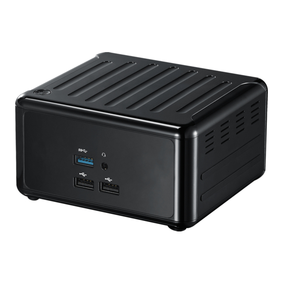
Chapter 2 Product Overview This chapter provides diagrams showing the location of important components of the 4X4 BOX-V1000/R1000. 2.1 Front View Description USB 3.0 (Type A) Audio(Mic-in, Line-out) 2 x USB 2.0 (Type A) Power Button... -
Page 11: Rear View
4X4 BOX-V1000/R1000 2.2 Rear View Description DC-IN HDMI 2 x USB 3.0 (Type A) 2 x DisplayPort 2 x RJ-45 * There are two LEDs on the LAN port. Please refer to the table below for the LAN port LED indications. ACT/LINK LED SPEED LED LAN Port... -
Page 12: Inside View
2.3 Inside View Description Mini PCIe Slot M.2 Slot SATA 3.0 Connectors SO-DIMM Slot Hard disk drive tray (compatible with 2.5" SATA HDD/SSD) SO-DIMM memory, hard drive and mSATA SSD are not included with this system. -
Page 13: Chapter 3 Hardware Installation
4X4 BOX-V1000/R1000 Chapter 3 Hardware Installation This chapter helps you install or remove important components. 3.1 How to Remove the Bottom Case 1. Remove the four screws on the bottom case. 2. Then lift up and remove the bottom panel.. -
Page 14: How To Install The Wifi Module
3.2 How to Install the WiFi Module 1. Locate the WiFi Module slot on the motherboard. 2. Carefully insert the WiFi Module into the slot. 3. Tighten the screw to secure the WiFi Module to the motherboard. -
Page 15: How To Install The M.2 Ssd
4X4 BOX-V1000/R1000 3.3 How to Install the M.2 SSD 1. Locate the M.2 slot on the motherboard. 2. Carefully insert the M.2 SSD into the slot. 3. Tighten the screw to secure the M.2 SSD to the motherboard. -
Page 16: How To Install The 2.5-Inch Hard Drive
3.4 How to Install the 2.5-inch Hard Drive 1. Remove the four screws on the bottom case. Then lift up and remove the bottom panel. 2. Attach the HDD to the hard drive mounting bracket and secure it using the four screws. - Page 17 4X4 BOX-V1000/R1000 3. Attach the HDD assembly to the bottom panel and secure it using the four screws. Connect the SATA Data and Power Cable to the HDD. 4. Then reinstall the bottom panel.
-
Page 18: How To Install The Memory Modules (Ddr4 Low Voltage (1.2V))
3.5 How to Install the Memory Modules (DDR4 Low Voltage (1.2V)) 1. The 4X4 BOX-V1000/R1000 requires DDR4 SO-DIMM (1.2V). 2. For dual channel configuration, you always need to install identical (the same brand, speed, size and chip-type) DDR4 SO-DIMM pairs. The SO-DIMM only fits in one correct orientation. -
Page 19: How To Install The M.2 Heatsink
4X4 BOX-V1000/R1000 3.6 How to Install the M.2 Heatsink 1. Gently insert the M.2 module, along the guiding tabs, into the heatsink bracket. 2. Remove the membranes from both sides of the thermal pad. Then paste the thermal pad onto the M.2 module. 3. -
Page 20: Chapter 4 Motherboard
Chapter 4 Motherboard 4.1 Motherboard Layout USB2_0_5 PANEL1 PLED PWRBTN BIOS USB 3.1: USB3_3 HDLED RESET AUDIO1 COM1 SATA_PWR1 Industrial SATA3_1 DDR4_B1 (Support DDR4 Only) DC_IN1 DDR4_A1 (Support DDR4 Only) 1 : M.2 Key-M Socket (M2M_1) 2 : M.2 Key-E Socket (M2E_1) 3 : COM Port Header (RS232/422/485) 4 : System Panel Header (PANEL1) 5 : USB2.0 Connector (USB2_0_5) -
Page 21: Motherboard Specifications
4X4 BOX-V1000/R1000 4.2 Motherboard Specifications Form Dimensions NUC 4.09" x 4.02" (104 x 102mm) Factor AMD Ryzen™ Embedded R-Series (R1606G, DC, 2.6GHz, 12-25W) (4X4-R1000M) Processor (R1505G, DC, 2.4GHz, 12-25W) (4X4-R1000V) System AMD Ryzen™ Embedded V-Series (V1605B, QC, 2GHz, 12-25W) (4X4-V1000M) Chipset 1 x Key M (2242/2260/2280 by BRACKET) with Expansion... - Page 22 2 x USB 2.0 Serial 1 x COM (RS-232/422/485) Internal SATA 1 x SATA3 (6.0Gb/s) Connector SATA PWR Output 1 x Header Watchdog Output From Super I/O to drag RESETCON# Timer Interval 256 segments, 0,1,2…255sec Input PWR 12V only (DC Jack) AT/ATX Supported Power AT: Directly PWR on as Power input ready...
-
Page 23: Jumpers Setup
4X4 BOX-V1000/R1000 4.3 Jumpers Setup The illustration shows how jumpers are setup. When the jumper cap is placed on pins, the jumper is “Short”. If no jumper cap is placed on pins, the jumper is “Open”. The illustration shows a 3-pin jumper whose pin1 and pin2 are “Short”... -
Page 24: Onboard Headers And Connectors
4.4 Onboard Headers and Connectors Onboard headers and connectors are NOT jumpers. Do NOT place jumper caps over these headers and connectors. Placing jumper caps over the headers and connectors will cause permanent damage of the motherboard! SATA3 Connector This Serial ATA3 (SATA3) connector supports SATA data (SATA3_1: see p.16, No. - Page 25 4X4 BOX-V1000/R1000 RESET (Reset Switch): Connect to the reset switch on the chassis front panel. Press the reset switch to restart the computer if the computer freezes and fails to perform a normal restart. PLED (System Power LED): Connect to the power status indicator on the chassis front panel. The LED is on when the system is operating.
- Page 26 Back Side: Power Button Header (PWR_BTN3) Fan Connector +12V (FAN1) FAN_SPEED FAN_SPEED_CONTROL...
-
Page 27: Expansion Slots (M.2 Slots)
4X4 BOX-V1000/R1000 4.5 Expansion Slots (M.2 Slots) There are 2 M.2 slots on this motherboard. M.2 for SSD: Key M (M2_1) (2242/2260/2280 by BRACKET) supports PCIe x4 and SATA3 for SSD. M.2 for Wi-Fi: Key E (M2_2) (2230) supports PCIe x1 and USB 2.0 for Wireless. M.2 Key-M Socket (M2M_1) M.2 Key-E Socket (M2E_1) -
Page 28: Chapter 5 Uefi Setup Utility
Chapter 5 UEFI Setup Utility 5.1 Introduction This section explains how to use the UEFI SETUP UTILITY to configure your system. The UEFI chip on the motherboard stores the UEFI SETUP UTILITY. You may run the UEFI SETUP UTILITY when you start up the computer. Please press <F2> or <Del> during the Power-On-Self-Test (POST) to enter the UEFI SETUP UTILITY, otherwise, POST will continue with its test routines. -
Page 29: Main Screen
4X4 BOX-V1000/R1000 5.1.2 Navigation Keys Please check the following table for the function description of each navigation key. Navigation Key(s) Function Description Moves cursor left or right to select Screens Moves cursor up or down to select items + / - To change option for the selected items <Enter>... -
Page 30: Advanced Screen
5.3 Advanced Screen In this section, you may set the configurations for the following items: CPU Configu- ration, Chipset Configuration, Storage Configuration, Super IO Configuration, ACPI Configuration, USB Configuration and Trusted Computing. Setting wrong values in this section may cause the system to malfunction. Instant Flash Instant Flash is a UEFI flash utility embedded in Flash ROM. This conve- nient UEFI update tool allows you to update system UEFI without entering ® operating systems first like MS-DOS or Windows . - Page 31 4X4 BOX-V1000/R1000 5.3.1 CPU Configuration Cool ‘n‘ Quiet Use this item to enable or disable AMD’s Cool ‘n’ QuietTM technology. The default value is [Enabled]. Configuration options: [Enabled] and [Dis- ® abled]. If you install Windows OS and want to enable this function, please set this item to [Enabled]. Please note that enabling this function may re- duce CPU voltage and memory frequency, and lead to system stability or compatibility issue with some memory modules or power supplies.
- Page 32 5.3.2 Chipset Configuration Share Memory Configure the size of memory that is allocated to the integrated graphics processor when the system boots up. Onboard HD Audio Select [Enabled] or [Disabled] for the onboard HD Audio feature. Onboard LAN 1 This allows you to enable or disable the Onboard LAN 1. Onboard LAN 2 This allows you to enable or disable the Onboard LAN 2.
- Page 33 4X4 BOX-V1000/R1000 5.3.3 Storage Configuration SATA Controller(s) Use this item to enable or disable the SATA Controller feature. SATA Mode Selection Use this to select SATA mode. The default value is [AHCI Mode]. AHCI (Advanced Host Controller Interface) supports NCQ and other new features that will improve SATA disk perfor- mance but IDE mode does not have these advantages.
- Page 34 5.3.4 Super IO Configuration COM1 Configuration Use this to set parameters of COM1. Type Select Use this to select COM3 port type: [RS232], [RS422] or [RS485]. WDT Timeout Reset Use this to set the Watch Dog Timer.
- Page 35 4X4 BOX-V1000/R1000 5.3.5 ACPI Configuration Suspend to RAM Use this item to select whether to auto-detect or disable the Suspend-to- RAM feature. Select [Auto] will enable this feature if the OS supports it. ACPI HPET Table Enable the High Precision Event Timer for better performance. Onboard LAN Power On Use this item to enable or disable onboard LAN to turn on the system from the power-soft-off mode.
- Page 36 5.3.6 USB Configuration Legacy USB Support Use this option to select legacy support for USB devices. There are two configuration options: [Enabled] and [UEFI Setup Only]. The default value is [Enabled]. Please refer to below descriptions for the details of these two options: [Enabled] - Enables support for legacy USB. [UEFI Setup Only] - USB devices are allowed to use only under UEFI setup and Windows / Linux OS.
- Page 37 4X4 BOX-V1000/R1000 5.3.7 Trusted Computing Security Device Support Enable or disable BIOS support for security device.
-
Page 38: Hardware Health Event Monitoring Screen
5.4 Hardware Health Event Monitoring Screen In this section, it allows you to monitor the status of the hardware on your system, including the parameters of the CPU temperature, motherboard temperature, CPU fan speed, chassis fan speed, and the critical voltage. Fan 1 Setting This allows you to set fan 1’s speed. Configuration options: [Full On] and [Automatic Mode]. -
Page 39: Security Screen
4X4 BOX-V1000/R1000 5.5 Security Screen In this section, you may set, change or clear the supervisor/user password for the system. Supervisor Password Set or change the password for the administrator account. Only the ad- ministrator has authority to change the settings in the UEFI Setup Utility. Leave it blank and press enter to remove the password. -
Page 40: Boot Screen
5.6 Boot Screen In this section, it will display the available devices on your system for you to config- ure the boot settings and the boot priority. Boot From Onboard LAN Use this item to enable or disable the Boot From Onboard LAN feature. Setup Prompt Timeout This shows the number of seconds to wait for setup activation key. 65535(0XFFFF) means indefinite waiting. - Page 41 4X4 BOX-V1000/R1000 CSM (Compatibility Support Module) Enable to launch the Compatibility Support Module. Please do not disable unless you’re running a WHCK test. If you are using Windows 8.1 64-bit and all of your devices support UEFI, you may also disable CSM for faster boot speed.
-
Page 42: Exit Screen
5.7 Exit Screen Save Changes and Exit When you select this option, it will pop-out the following message, “Save configuration changes and exit setup?” Select [OK] to save the changes and exit the UEFI SETUP UTILITY. Discard Changes and Exit When you select this option, it will pop-out the following message, “Discard changes and exit setup?” Select [OK] to exit the UEFI SETUP UTILITY without saving any changes. -
Page 43: Chapter 6 Software Support
4X4 BOX-V1000/R1000 Chapter 6 Software Support 6.1 Install Operating System ® ® This motherboard supports various Microsoft Windows operating systems: 10 64-bit. Because motherboard settings and hardware options vary, use the setup procedures in this chapter for general reference only. Refer your OS documentation for more information.