Table of Contents
Advertisement
Quick Links
SERVICE MANUAL
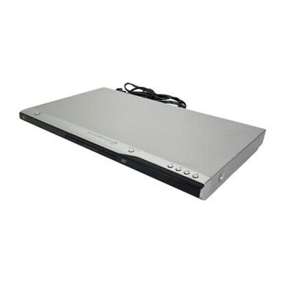
Product Type: DVD VIDEO PLAYER
Chassis: DP-10 (MD)
Manual Series: DVB611
Manual Part #: 3829RHP051M
Model Line: D
Product Year: 2006
CONTENTS
....................................................
Summary
Cabinet & Main Chassis
Electrical
....................................................
Parts List
....................................................
Published March 2006
by Technical Publications
Zenith Electronics Corporation
201 James Record Road
Huntsville, Alabama 35824-1513
Copyright © 2006 by Zenith Electronics Corporation
Printed in U.S.A
Model Series:
DVB611
1
.............................
2
3
4
Advertisement
Chapters
Table of Contents

Related Manuals for Zenith DVB611


Summary of Contents for Zenith DVB611
- Page 1 Product Year: 2006 CONTENTS ............ Summary Cabinet & Main Chassis ......Electrical ............ Parts List ............ Published March 2006 by Technical Publications Zenith Electronics Corporation 201 James Record Road Huntsville, Alabama 35824-1513 Copyright © 2006 by Zenith Electronics Corporation Printed in U.S.A...
- Page 2 CONTENTS SECTION 1 ..SUMMARY SECTION 2 ..CABINET & MAIN CHASSIS SECTION 3 ..ELECTRICAL SECTION 4 ..REPLACEMENT PARTS LIST...
-
Page 3: Table Of Contents
SECTION 1 SUMMARY CONTENTS PRODUCT SAFETY SERVICING GUIDELINES FOR VIDEO PRODUCTS ......1-3 SERVICING PRECAUTIONS ....................1-4 • General Servicing Precautions • Insulation Checking Prodedure • Electrostatically Sensitive Devices SERVICE INFORMATION FOR EEPROM ................1-5 SPECIFICATIONS ........................1-6... -
Page 4: Product Safety Servicing Guidelines For Video Products
PRODUCT SAFETY SERVICING GUIDELINES FOR VIDEO PRODUCTS CAUTION : DO NOT ATTEMPT TO MODIFY THIS PRODUCT IN ANY WAY, SUBJECT : X-RADIATION NEVER PERFORM CUSTOMIZED INSTALLATIONS WITHOUT MANUFAC- 1. BE SURE PROCEDURES AND INSTRUCTIONS TO ALL SERVICE PER- TURER’S APPROVAL. UNAUTHORIZED MODIFICATIONS WILL NOT ONLY SONNEL COVER THE SUBJECT OF X-RADIATION. -
Page 5: Servicing Precautions
SERVICING PRECAUTIONS CAUTION : Before servicing the DVD covered by this service Electrostatically Sensitive (ES) Devices data and its supplements and addends, read and follow the Some semiconductor (solid state) devices can be damaged SAFETY PRECAUTIONS. NOTE : if unforeseen circum- easily by static electricity. -
Page 6: Service Information For Eeprom
SERVICE INFORMATION FOR EEPROM POWER ON DETECT NEW EEPROM DVD LOGO Status (NO Disk status) (OPTION EDIT SCREEN) MODEL DVB611 NAME Remotecontrol OPT 1 55(U) Pause key-->1-->4-->7-->2 in order. OPT 2 53(S) OPT 3 00(ENG) OPT 4 OPT 5 Press number 0~9, Press charater... -
Page 7: Specifications
SPECIFICATIONS • GENERAL Power requirements: AC 120V , 60Hz Power consumption: Dimensions (Approx.): 430 x 35 x 242 mm (17 x 1.4 x 9.5 inches) (W x H x D) with- out foot Weight (Approx.): 1.7 kg (3.7 lbs) Operating temperature: 5 °C to 35 °C (41 °F to 95 °F) Operating humidity: 5 % to 90 %... - Page 8 SECTION 2 CABINET & MAIN CHASSIS CONTENTS EXPLODED VIEWS ........................2-2 1. Cabinet and Main Frame Section ...................2-2 2. Deck Mechanism Section(DP-10) ...................2-3 3. Packing Accessory Section ....................2-4 7 2-1...
-
Page 9: Exploded Views
EXPLODED VIEWS 1. Cabinet and Main Frame Section NOTES) THE EXCLAMATION POINT WITHIN AN EQUILATERAL TRIANGLE IS INTENDED TO ALERT THE SERVICE PERSONNEL TO THE PRESENCE OF IMPORTANT SAFETY INFORMATION IN SERVICE LITERATURE. 8 2-2... -
Page 10: Deck Mechanism Section(Dp-10)
2. Deck Mechanism Section(DP-10) -
Page 11: Packing Accessory Section
3. Packing Accessory Section RF CABLE 810 CABLE SET ASS’Y PLUG ASS’Y 1WAY(YELLOW) PLUG ASS’Y 2WAY BATTERY PLUG ASS’Y 1WAY(BLACK) REMOCON OWNER’S MANUAL PACKING SHEET PACKING PACKING BOX CARTON OPTIONAL PARTS... - Page 12 SECTION 3 ELECTRICAL CONTENTS ELECTRICAL TROUBLESHOOTING GUIDE ..............3-2 1. Power check flow........................3-2 2. System operation flow ......................3-3 3. Test & debug flow ........................3-4 DETAILS AND WAVEFORMS ON SYSTEM TEST AND DEBUGGING ....3-10 1. SYSTEM 27MHz CLOCK, RESET SIGNAL................3-10 2. SDRAM CLOCK ........................3-12 3.
-
Page 13: Electrical Troubleshooting Guide
ELECTRICAL TROUBLESHOOTING GUIDE 1. Power check flow No 5V No 3.4VA. Is 3.4VA section working? Is 3.4VA section working? Is 5.6V present at collector Is 3.4V present at emitter No 3.4VA of Q126? of Q121? Replace Q126. Check FR101 Replace Q121. Check D105/D106/D107/ Is there a DC voltage at Cathode of D105 or D107? -
Page 14: System Operation Flow
2. System operation flow Power On 1. 186 CPU initializes SERVO,DSP & RISC registers 2. Write RISC code to SDRAM 3. Reset RISC Show LOGO Tray Closed ? Tray Close to Closed position SLED at Inner Side ? SLED Moves to Inner Position 1. -
Page 15: Test & Debug Flow
3. Test & debug flow TEST Check the AC Voltage Replace power PCBA or AC transformer. Power PCBA(110V or 220V) Switch on the Power PCBA Is the DC Voltage outputs OK? Repair or Replace Power PCBA (5V, 3.3V, 12V, 5.6V MOTOR) Make sure the main PCBA don't short on VCCs and switch it on. - Page 16 RESET or Power On. Check connection lines between Flash Memory operates Show LOGO? FLASH & ZR336888 and the FLASH properly? access time whether is suitable or not. Check connection lines SDRAM works properly? between SDRAM & ZR36882 and the SDRAM is damaged. ZR36882 VIDEO outputs Check the related circuit of properly?
- Page 17 Does the SLED move to Motor Driver MUTE Pin is Check the connection line of inner side when it is at outter High? MUTE signal. position? Is SLED_S DC Level higher Check the related circuit of than 1.65V? FMSO. SLED+ and SLED- output Check the amp circuit on properly? motor driver.
- Page 18 Check the laser power circuit Laser turns on when LD_DVD or LD_CD on ZR36882 and connecting reading disc? output properly? to power transistor. Collector voltage of power Check the related circuit on transistor is OK? laser power transistor Check cable connection between transistor ouput and pick-up head.
- Page 19 Proper signals on A,B,C,D Check connections between Focus ON OK? of ZR36882 ZR36882 and pick-up head. Check the FOCUS_S Check FE signal on connection on ZR36882 ZR36882 and motor driver. Check FOCUS_S signal on ZR36882 Normal TE Signal on Check the related Track On OK? ZR36882? circuit on ZR36882...
- Page 20 Normal Audio output Audio DAC received Check connection between when disc playback? correct data stream? ZR36882 & Audio DAC. Check the related circuit of Normal Audio DAC out? Audio DAC. Check Audio filter, amplify, mute circuit. Communications between Normal IR.VFD & Front Check communication lines IR.VFD Front panel key &...
-
Page 21: Details And Waveforms On System Test And Debugging
DETAILS AND WAVEFORMS ON SYSTEM TEST AND DEBUGGING 1. SYSTEM 27MHz CLOCK, RESET SIGNAL 1) ZR36882 main clock is at 27MH(X601) 3.1V,27MHz FIG 1-1 2) ZR3682 reset is low active 3.3VA PWR_CTL RESET Reset Time FIG 1-2 3-10... -
Page 22: Sdram Clock
2. SDRAM CLOCK 1) SDRAM clock is at 143MHz CLK=143MHz,Vp-p=3.3V IC603 PIN38 FIG 2-1 3. TRAY OPEN/CLOSE SIGNAL 1) Tray open/close waveform OPEN CLOSE OPEN CLOSE FIG 3-1 3-11... - Page 23 2) Tray open waveform OPEN CLOSE FIG 3-2 3) Tray close waveform OPEN CLOSE FIG 3-3 3-12...
-
Page 24: Sled Control Related Signal(No Disc Condition)
4. SLED CONTROL RELATED SIGNAL(NO DISC CONDITION) SLED_S DRVSB SLED+ SLED- FIG 4-1 5. LENS CONTROL RELATED SIGNAL(NO DISC CONDITION) FOCUS_S FOCUS+ FOCUS- FIG 5-1 3-13... -
Page 25: Laser Power Control Related Signal(No Disc Condition)
6. LASER POWER CONTROL RELATED SIGNAL(NO DISC CONDITION) DCLK = 128MHz, Vp-p=2.2, Vmax=2.7V VR_CD DVD_LD CD_LD FIG 6-1 7. DISC TYPE JUDGEMENT WAVEFORM FACT+ SBAD FIG 7-1(DVD) 3-14... - Page 26 FACT+ SBAD FIG 7-2 (DVD) FACT+ SBAD FIG 7-3 (CD) 3-15...
-
Page 27: Focus On Waveform
FACT+ SBAD FIG 7-4 (CD) 8. FOCUS ON WAVEFORM FOSO FACT+ FACT- FIG 8-1 (DVD) 3-16... -
Page 28: Spindle Control Waveform
FOCUS FACT+ FACT- FIG 8-2 (CD) 9. SPINDLE CONTROL WAVEFORM(NO DISC CONDITION) SPINDLE_S (DVD) FIG 9-1 3-17 3-17... -
Page 29: Tracking Control Related Signal(System Checking)
10. TRACKING CONTROL RELATED SIGNAL(System checking) TRACK_S TACT+ TACT- FIG 10-1 (DVD) TRACK_S TACT+ TACT- FIG 10-2 (CD) 3-18... -
Page 30: Rf Waveform
11. RF WAVEFORM FIG 11-1 12. ZR36882 AUDIO OPTICAL AND COAXIAL OUTPUT(SPDIF) SPDIF FIG 12-1 3-19... -
Page 31: Zr36882 Video Output Waveform
13. ZR36882 VIDEO OUTPUT WAVEFORM 1) Full colorbar signal(CVBS) JK702 pin6 FIG 13-1 2) Y JK702 pin7 FIG 13-2 3-20... -
Page 32: Audio Output From Audio Dac
3) C JK702 PIN8 FIG 13-3 14. AUDIO OUTPUT FROM AUDIO DAC 1) AUDIO L/R 1KHz 0DB JK702 PIN4,5 FIG 14-1 3-21... - Page 33 2) Audio Related Signal AOUT0 ABCK ALRCLK FIG 14-2 3-22...
-
Page 34: Block Diagrams
BLOCK DIAGRAMS 1. Overall Block Diagram CVBS RESET 3-23... -
Page 35: Power(Smps) Block Diagram
2. Power(SMPS) Block Diagram TRANS SWITCHING IC AC100~240V FILTER RECTIFIER 3-24... -
Page 36: Servo Block Diagram
3. SERVO Block Diagram 3-25... -
Page 37: Mpeg & Memory Block Diagram
4. MPEG & MEMORY Block Diagram 3-26... -
Page 38: Video & Audio Block Diagram
5. VIDEO & AUDIO Block Diagram 3-27... -
Page 40: Circuit Diagrams
2. Voltages are DC-measured with a digital voltmeter MODIFIED OR ALTERED WITHOUT PERMISSION IMPLEMENTATION OF THE LATEST SAFETY AND during Play mode. FROM THE ZENITH ELECTRONICS CORPORATION. PERFORMANCE IMPROVEMENT CHANGES INTO ALL COMPONENTS SHOULD BE REPLACED ONLY THE SET IS NOT DELAYED UNTIL THE NEW SERVICE WITH TYPES IDENTICAL TO THOSE IN THE ORIGI- LITERATURE IS PRINTED. -
Page 41: System Circuit Diagram
2. SYSTEM CIRCUIT DIAGRAM 3-30 3-31... -
Page 42: Servo Circuit Diagram
3. SERVO CIRCUIT DIAGRAM 3-32 3-33... -
Page 43: Av/Jackcircuit Diagram
4. AV/JACK CIRCUIT DIAGRAM 3-34 3-35... -
Page 44: Timer Circuit Diagram ( 3 Tool Only)
5. TIMER CIRCUIT DIAGRAM ( 3 TOOL ONLY) 3-36 3-37... -
Page 45: Timer Circuit Diagram ( 4 Tool Only)
6. TIMER CIRCUIT DIAGRAM ( 4 TOOL ONLY) 3-38 3-39... -
Page 46: Timer Circuit Diagram ( 6 Tool Only)
7. TIMER CIRCUIT DIAGRAM ( 6 TOOL ONLY) 3-40 3-41... -
Page 47: Timer Circuit Diagram ( 7 Tool Only)
8. TIMER CIRCUIT DIAGRAM ( 7 TOOL ONLY) 3-42 3-43... -
Page 48: Timer Circuit Diagram ( 8 Tool Only)
9. TIMER CIRCUIT DIAGRAM ( 8 TOOL ONLY) 3-44 3-45... -
Page 49: Circuit Voltage Chart
• CIRCUIT VOLTAGE CHART MODE MODE MODE MODE MODE MODE MODE MODE (PLAY) (PLAY) STOP PLAY STOP PLAY STOP PLAY STOP PLAY STOP PLAY STOP PLAY STOP PLAY condenser PIN NO. PIN NO. PIN NO. PIN NO. PIN NO. PIN NO. PIN NO. -
Page 50: Printed Circuit Diagrams
PRINTED CIRCUIT DIAGRAMS 1. MAIN P.C.BOARD ( TOP VIEW ) ( BOTTOM VIEW ) 3-48 3-49... -
Page 51: Key P.c.board
2. KEY P.C.BOARD 3. TIMER P.C.BOARD ( TOP VIEW ) ( BOTTOM VIEW ) LOCATION GUIDE LOCATION GUIDE 3-50 3-51... -
Page 52: Smps P.c.board(360Mm Only)
4. SMPS P.C.BOARD(360mm ONLY) 5. SMPS P.C.BOARD(430mm ONLY) LOCATION GUIDE 3-52 3-53... - Page 54 R03P SHANGHAI SHENKANG 1.5V 4A 841-0021 BATTERY,MN ER03X HI WATT 1.5V .MA/H AAA ALTERNATE 6711R1P089D REMOTE CONTROLLER ASSEMBLY U2 DZ9711ND HA1ULZ ZENITH *** BOARD ASSEMBLY *** 3501RF0943B BOARD ASSEMBLY DVD DV172NZ HA1ULZ BOARD ASSY 3721R-F941B PANEL ASSEMBLY,FRONT DVD DV172NZ HA1ULZ F/PANEL ASS...
- Page 55 S AL LOCA. NO. PART NO. DESCRIPTION SPECIFICATION REMARKS R907 0RH0471C622 RESISTOR,METAL GLAZED(CHIP) 4.7 OHM 1 / 16 W 1608 5.00% D R908 0RH3300C622 RESISTOR,METAL GLAZED(CHIP) 330 OHM 1 / 16 W 1608 5.00% D 6871R-9884A PWB(PCB) ASSEMBLY,TOTAL DZ17X 7TOOL KEY CN903 561-712B CONNECTOR (CIRC),WAFER...
- Page 56 S AL LOCA. NO. PART NO. DESCRIPTION SPECIFICATION REMARKS C6A2 0CE1074F638 CAPACITOR,FIXED ELECTROLYTIC 100UF SRA,SS 16V 20% FM5 TP 5 C6C9 0CE2274C638 CAPACITOR,FIXED ELECTROLYTIC 220UF SRA,SS 6.3V 20% FM5 TP 5 C6F7 0CE2274C638 CAPACITOR,FIXED ELECTROLYTIC 220UF SRA,SS 6.3V 20% FM5 TP 5 C6J1 0CE1064F638 CAPACITOR,FIXED ELECTROLYTIC...
- Page 57 S AL LOCA. NO. PART NO. DESCRIPTION SPECIFICATION REMARKS C629 0CH1103K562 CAPACITOR,FIXED CERAMIC(TEMP.C 0.01UF 50V 10% X7R(X) 1608 R/T C631 0CH1103K562 CAPACITOR,FIXED CERAMIC(TEMP.C 0.01UF 50V 10% X7R(X) 1608 R/T C632 0CH1103K562 CAPACITOR,FIXED CERAMIC(TEMP.C 0.01UF 50V 10% X7R(X) 1608 R/T C633 0CH1103K562 CAPACITOR,FIXED CERAMIC(TEMP.C 0.01UF 50V 10% X7R(X) 1608 R/T...
- Page 58 S AL LOCA. NO. PART NO. DESCRIPTION SPECIFICATION REMARKS C6F4 0CH1104K942 CAPACITOR,FIXED CERAMIC(TEMP.C 0.1UF 50V 80%,-20% Y5V(F) 1608 C6F5 0CH1104K942 CAPACITOR,FIXED CERAMIC(TEMP.C 0.1UF 50V 80%,-20% Y5V(F) 1608 C6F6 0CH1104K942 CAPACITOR,FIXED CERAMIC(TEMP.C 0.1UF 50V 80%,-20% Y5V(F) 1608 C6H1 0CH1102K562 CAPACITOR,FIXED CERAMIC(TEMP.C 1000PF 50V 10% X7R(X) 1608 R/T C6H2 0CH1333K562...
- Page 59 S AL LOCA. NO. PART NO. DESCRIPTION SPECIFICATION REMARKS L605 6200S-JC01B FILTER(CIRC),EMC HB-1M2012-221JT CERATECH TP L606 6200HJC102A FILTER(CIRC),EMC HB-1M2012-102JT CERATECH TP L607 6200S-JC01B FILTER(CIRC),EMC HB-1M2012-221JT CERATECH TP L609 0LCCE00041A INDUCTOR,CHIP HB_1M1608_301JT CERATECH R/TP L610 6200S-JC01B FILTER(CIRC),EMC HB-1M2012-221JT CERATECH TP L6A2 6200S-JC01B FILTER(CIRC),EMC HB-1M2012-221JT CERATECH TP...
- Page 60 S AL LOCA. NO. PART NO. DESCRIPTION SPECIFICATION REMARKS R214 0RH0332C622 RESISTOR,METAL GLAZED(CHIP) 33 OHM 1 / 16 W 1608 5.00% D R216 0RH2200C622 RESISTOR,METAL GLAZED(CHIP) 220 OHM 1 / 16 W 1608 5.00% D R217 0RH0331C622 RESISTOR,METAL GLAZED(CHIP) 3.3 OHM 1 / 16 W 1608 5.00% D R218 0RH2200C622 RESISTOR,METAL GLAZED(CHIP)
- Page 61 S AL LOCA. NO. PART NO. DESCRIPTION SPECIFICATION REMARKS R6A3 0RH3301C622 RESISTOR,METAL GLAZED(CHIP) 3.3K OHM 1 / 16 W 1608 5.00% D R6A4 0RH2200C622 RESISTOR,METAL GLAZED(CHIP) 220 OHM 1 / 16 W 1608 5.00% D R6A5 0RH2200C622 RESISTOR,METAL GLAZED(CHIP) 220 OHM 1 / 16 W 1608 5.00% D R6A6 0RH2200C622 RESISTOR,METAL GLAZED(CHIP)
- Page 62 S AL LOCA. NO. PART NO. DESCRIPTION SPECIFICATION REMARKS C110 0CG1020U630 CAPACITOR,FIXED CERAMIC(TEMP.C 1000PF D 400V 20% E(Z5U) R C111 0CG1020U630 CAPACITOR,FIXED CERAMIC(TEMP.C 1000PF D 400V 20% E(Z5U) R C113 0CN1020K518 CAPACITOR TUBULA(HIGH DIELE) 1000P 50V TA26 C121 0CE108BF630 CAPACITOR,FIXED ELECTROLYTIC 1000UF KME TYPE 16V 20% FM5 BU C121 0CE108EF630...
- Page 63 S AL LOCA. NO. PART NO. DESCRIPTION SPECIFICATION REMARKS Q123 0TR320309AA TRANSISTOR,BIPOLARS KTC3203 KEC TP TO92 50V 150MA ALTERNATE Q124 0TR220309AF TRANSISTOR,BIPOLARS SRA2203 TP AUK TO92 22K,22K Q124 0TR103009AF TRANSISTOR,BIPOLARS KRA103M(KRA2203) KEC TP TO92M ALTERNATE Q126 0TR232809AB TRANSISTOR,BIPOLARS KSC2328A-Y TP SAMSUNG TO-92L - Q126 0TR186209AB TRANSISTOR,BIPOLARS...